

Page 1
Commercial Microelectronic
APPLICATION
The T7300D Series 2000 Commercial Microelectronic
Thermostat provides electronic control of 24 Vac
commercial single zone heating, ventilating and air
conditioning (HVAC) equipment. It is designed for use
with Q7300A,G,L subbases for conventional heat/cool
applications. The T7300D is field configurable for
automatic or manual changeover between heating and
cooling. The system and fan selections are done by a
keyboard entry. All T7300D Thermostats require a
common wire to supply power.
RECYCLING NOTICE
If this control is replacing a control that contains
mercury in a sealed tube, do
control in the trash.
Contact your local waste management authority for
instructions regarding recycling and the proper
disposal of the old thermostat.
not
place your old
T7300D Series 2000
Thermostat
INSTALLATION INSTRUCTIONS
A.
ENGAGE TABS AT TOP OF THERMOSTAT AND SUBBASE OR WALLPLATE.
B.
PRESS LOWER EDGE OF CASE TO LATCH.
INSTALLATION
When Installing this Product...
1. Read these instructions carefully. Failure to follow
the instructions can damage the product or cause a
hazardous condition.
2. Check the ratings given in the instructions and on
the product to make sure the product is suitable for
your application.
3. Installer must be a trained, experienced service
technician.
4. After completing installation, use these instructions
to check out the product operation.
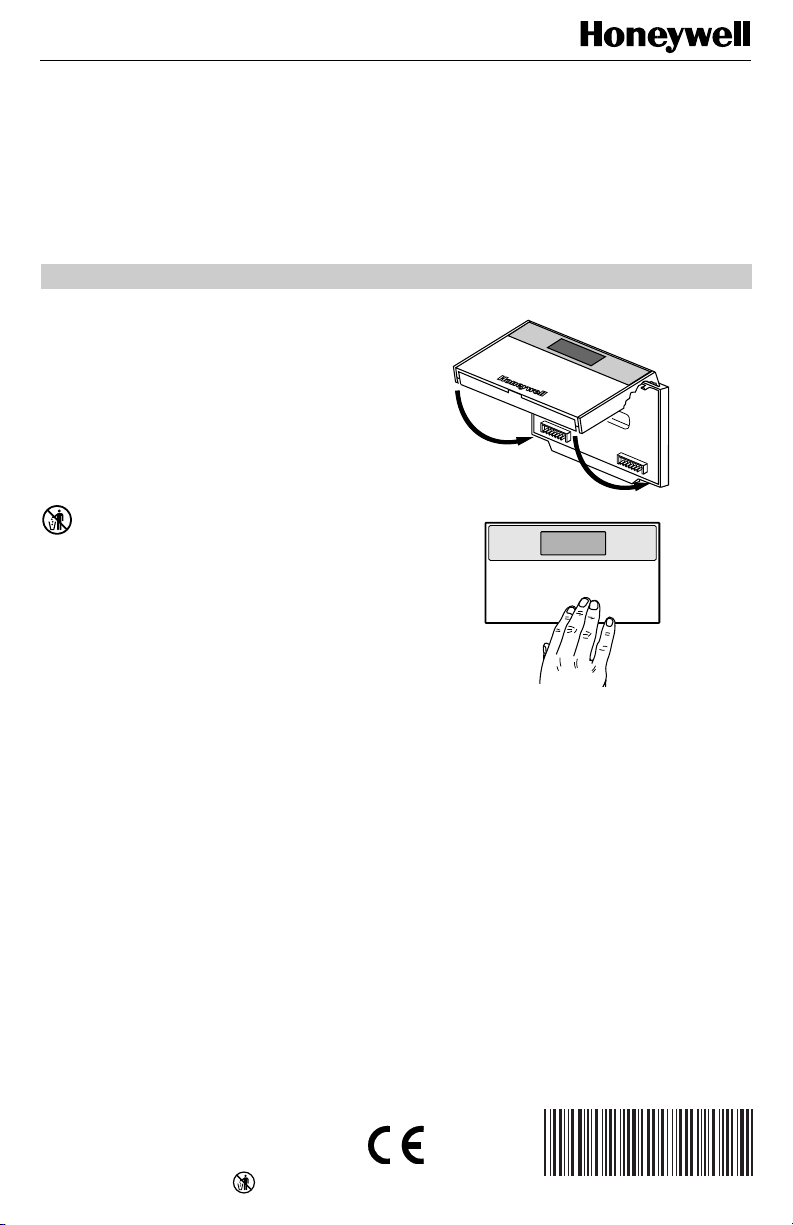
Mounting Thermostat on Subbase
The thermostat mounts on the subbase after it is installed.
1. Engage tabs at the top of thermostat and subbase.
See Fig. 1.
2. Press lower edge of case to latch.
NOTE: To remove the thermostat from the wall, first pull
out at the bottom of the thermostat; then remove
the top.
®U.S. Registered Trademark
Copyright © 1999 Honeywell Inc. • • All Rights Reserved
M4824A
Fig. 1. Mounting thermostat on subbase.
SETTINGS
Using Thermostat Keys
The thermostat keys are used to:
• set current time and day,
• program times and setpoints for heating and cooling,
• override the program temperatures,
• display present setting,
• set system and fan operation,
• configure Installer Setup,
• check Installer System Test.
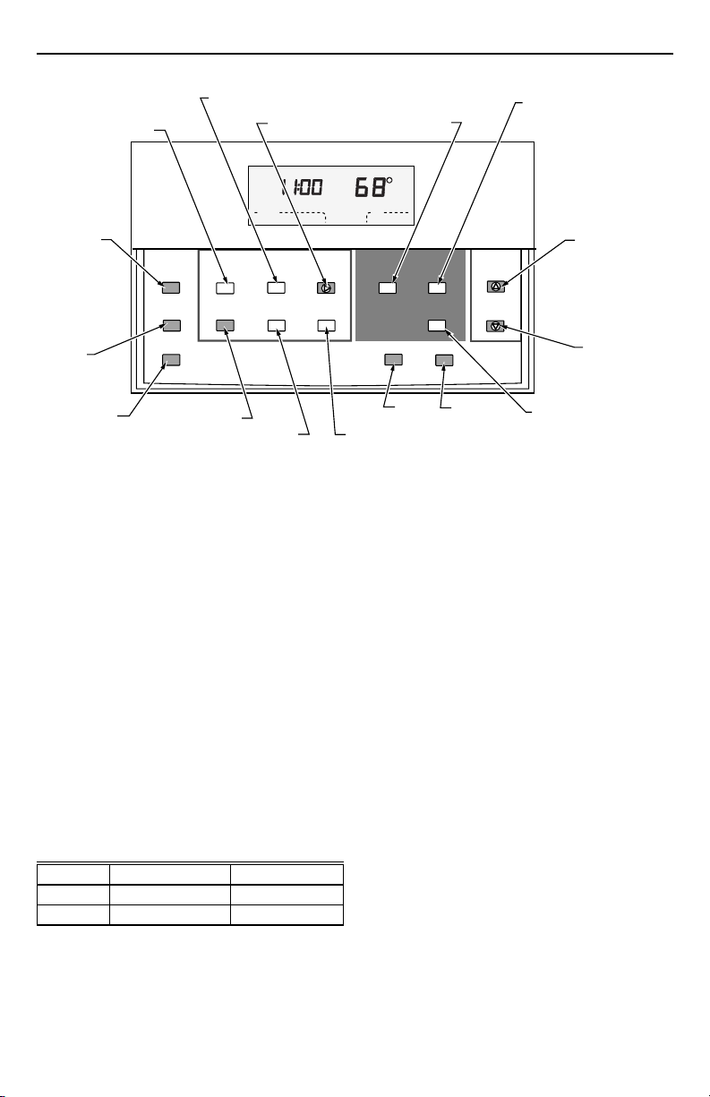
See Fig. 2 for key information.
X-XX UL
62-0132
Page 2
T7300D SERIES 2000 COMMERCIAL MICROELECTRONIC THERMOSTAT
ENTER UNOCCUPIED
ENTER OCCUPIED
PROGRAM MODE
RETURNS TO
NORMAL
OPERATIONS
SET OVERRIDE
TEMPERATURE
OFFSET AND
ACTIVATE
TEMPORARY
OVERRIDE
ENTER HOLD MODE
Program
Temporary
Occupied
Continuous
Unoccupied
PROGRAM MODE
Occupied
Run
Start Time
Set Current
Day/Time
SET CURRENT
DAY AND TIME
CLEAR PROGRAM PERIOD
SET CURRENT DAY OR
PROGRAM DAY
Mon
Occupied
System Fan
Heat
Set Program Set Temperature Change
Unoccupied
Start Time Day
Clear
Start Time
AM
Copy
COPY ONE
PROGRAMMED DAY
TO ANOTHER DAY
Fig. 2. Thermostat key locations and descriptions.
Setting System and Fan (select models)
The system default setting is Heat. The fan default is set
so the fan operates continuously in Occupied and Recovery
mode and with the heating or cooling equipment in
Unoccupied mode. Use the System and Fan keys to
change the settings.
The system settings are:
Heat: Thermostat controls the heating.
Off: Both the heating and cooling are off.
Cool: Thermostat controls the cooling.
Auto: Thermostat automatically changes between heating
and cooling operation depending on the indoor
temperature.
The fan settings are:
On: Fan operates continuously.
Auto: Equipment controls fan.
Setting Temperature
Refer to Table 1 for the default temperature setpoints. See
Owners Guide form number 63-4356 for complete
instructions on changing the setpoints.
Table 1. Default Temperature Setpoints.
Control Occupied Unoccupied
Heating 70°F (21°C) 55°F (13°C)
Cooling 78°F (25.5°C) 90°F (32°C)
SET OCCUPIED
TEMPERATURE
SETPOINTS
Room
Auto
Occupied
Unoccupied
Temp
System Fan
SELECT
SYSTEM
OPERATION
Temp
Heat/Cool
Settings
SELECT FAN
OPERATION
SET UNOCCUPIED TEMPERATURE
SETPOINTS AND SCROLLS
THROUGH INSTALLER SETUP
AND SYSTEM TEST
Time/Temp
CHANGE BETWEEN HEATING
AND COOLING SETPOINTS
AND SCROLLS BACKWARDS
THROUGH INSTALLER SETUP
NUMBERS AND SYSTEM TEST
INCREASE
TEMPERATURE
OR TIME SETTING
DECREASE
TEMPERATURE
OR TIME SETTING
M10233A
INSTALLER SETUP
NOTE: For most applications, the thermostat factory-
settings do not need to be changed. Review the
factory-settings in Table 2 and if no changes are
necessary, go to the Installer Self-Test section.
The Installer Setup is used by the installer to customize
the thermostat to specific systems. Installer Setup
numbers are listed in Table 2. The table includes all the
configuration options available.
A combination of key presses are required to use the
Installer Setup feature.
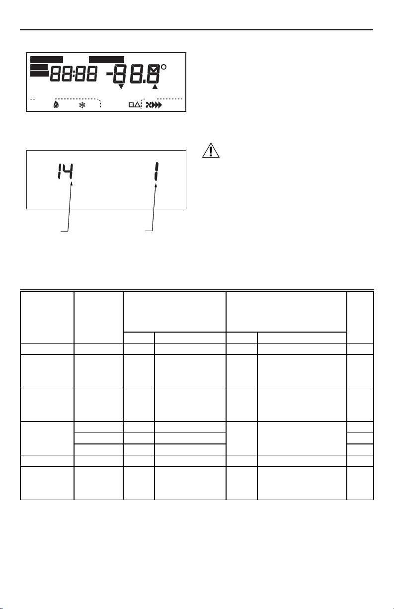
— To enter the Installer Setup, press and hold the Heat/
Cool Settings key with both the increase ▲ and ▼
decrease keys until the first number is displayed. All
display segments appear for approximately three
seconds before the number is displayed. See Fig. 3
and 4.
62-0132
2
Page 3
T7300D SERIES 2000 COMMERCIAL MICROELECTRONIC THERMOSTAT
Em Ht
Set Program
Set Day/Time
— To advance to the next Installer Setup number, press
the Unoccupied Temp key.
— To return to a previous Installer Setup number, press
the Heat/Cool Settings key.
— To change a setting, use the increase ▲ or ▼
decrease key.
— To exit the Installer Setup, press the Run Program
M4916
key. The Installer Setup is automatically exited if no
key presses are made for four minutes.
Installer Setup numbers are listed in Table 2.
CAUTION
Electric heat systems must be configured correcting in Installer Setup 2 to prevent equipment
damage caused by the system running without
the fan.
IMPORTANT
Only configurable numbers are shown on the
device. Example: If thermostat does not have a
system key, Installer Setup Number 12 will not be
displayed. Review Table 2 factory-settings and
mark any desired changes in the Actual Setting
column. When Installer Setup is complete,
review the settings to confirm that they match
the system.
AM
PM
Recovery
In
Lo
Med
Wait
Temporary Setting Enrg
Room
%Humid
Cool
Auto
Remote
Only
On
Duct
Auto
Heat
Hi
Sav
Set Program
Em Ht
Aux Ht
Comm
Mon
TueWedThuFriSatSun
Un
Occupied 12 Override
System Fan
Off Auto
Heat
Em
Start Time
Cool
Set Day/Time
Fig. 3. Display of all the segments of the LCD.
INSTALLER SETUP
NUMBER DISPLAY
(COLUMN 2
OF TABLE 2)
FACTORY SETTING
OR OTHER CHOICE
DISPLAY (COLUMN 3
OR 5 OF TABLE 2)
M10238B
Fig. 4. Display of Installer Setup number and setting.
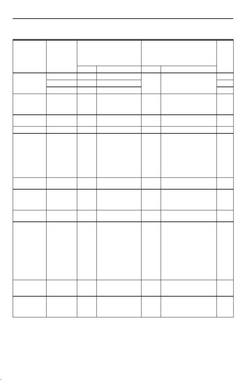
Table 2. Thermostat Installer Setup Options.
Installer Setup
Number
Select
(Press
Unoccupied
Temp key
to change)
Factory-Setting
Display Description Display Description
Other Choices
(Press ▲ or ▼ key to change)
Not used 1 — — — — —
Fan operation 2 0 Conventional applica-
Output stages of
heating
Heating cycle
rate
3 Depends
on
subbase
46Stage 1—4 cph 8
5 6 Stage 2—4 cph
tions where equipment
controls fan operation
in heat mode
Stages of heat 0, 1, 2,
1 Electric heat applications
or 3
where thermostat controls
fan operation in heat mode
0—No heating
1—One stage of heat
2—Two stages of heat
3—Three stages of heat
3, 4, 8, 9 cph
6 6 Stage 3—4 cph
Not used 7 — — — — —
Output stages
of cooling
8 Depends
on
subbase
Three stages of cool 0, 1, 2
or 3
0—No cooling
1—One stage of cool
2—Two stages of cool
3—Three stages of cool
(continued)
Actual
Setting
3
62-0132
Page 4
T7300D SERIES 2000 COMMERCIAL MICROELECTRONIC THERMOSTAT
Table 2. Thermostat Installer Setup Options (Continued).
Installer Setup
Number
(Press
Unoccupied
Temp key
Select
Cooling cycle
rate
System setting
adjustment
(models with
System key)
Degree temperature display
Clock format 16 0 12-hour clock format 1 24-hour clock format
Intelligent Fan™
operation
Auxiliary Contact
Operation
Fan key
adjustment
(models with Fan
key only)
Remote sensing 22 0 Remote sensing not
Keypad lockout
level (keypad
lockout is
enabled and
disabled by DIP
switch 1 on back
of thermostat)
Duration of
temporary
override
Minimum off time
for the
compressor
to change)
9 4 Stage 1—4 cph 3 3—3 cph
10 4 Stage 2—4 cph
11 4 Stage 3—4 cph
12 Depends
14 0 Temperature is
17 2 Fan operates
18 0 0—Time of day
21 0 Fan setting key is
25 0 No lockout 1 or 2, 3 1—Lockout all keys on
26 3 3—Three hour
33 4 4 minute minimum off
Factory-Setting
Display Description Display Description
on model
System selection 0, 1 or 2 0—System setting key is
displayed in °F
continuously in
Occupied and
Recovery mode. Fan
operates with call for
heating or cooling in
Unoccupied mode.
contacts
operational
activated
override
time for the
compressor
1 Temperature is displayed in
0 or 1 0—Fan only operates with
1 1—Economizer contacts —
1 Fan setting key is Auto only
1 Remote sensing activated
1, 8 or 12 1—One hour override
0, 1, 2, 3
or 5
Other Choices
(Press ▲ or ▼ key to change)
operational
1—Auto setting is disabled
2—Auto only setting
°C
calls for heating or cooling
in Occupied and
Unoccupied modes.
1—Fan operates
continuously in Occupied
mode. Fan operates with
calls for heating or cooling
in Unoccupied mode.
thermostat except system
and fan settings, temporary
setpoint, clock and day
adjustments
2—Lockout all keys except
Set Current Day/Time,
increase ▲ and decrease
▼ keys.
3—Lockout all keys except
Temporary Occupied, Set
Day and Clock keys
8—Eight hour override
12—Twelve hour override
Minimum number of minutes
(0 thru 5) the compressor will
be off between calls for the
compressor
Actual
Setting
(continued)
62-0132
4
Page 5

Select
Temperature
display
adjustment
Minimum off
times in heating
Installer Setup
lockout (keypad
lockout is
enabled and
disabled by DIP
switch 1 on back
of thermostat)
T7300D SERIES 2000 COMMERCIAL MICROELECTRONIC THERMOSTAT
Table 2. Thermostat Installer Setup Options (Continued).
Installer Setup
Number
(Press
Unoccupied
Temp key
to change)
37 0 No difference in
38 4 4—4 minute minimum
40 0 0—No Installer Setup
Factory-Setting
Display Description Display Description
displayed temperature
and actual room
temperature89
off time
lockout
Other Choices
(Press ▲ or ▼ key to change)
1 thru 6
0, 1, 2, 3,
or 5
1 1—Installer Setup lockout
1—Display adjusts to 1°F
higher than actual room
temperature
2—Display adjusts to 2°F
higher than actual room
temperature
3—Display adjusts to 3°F
higher than actual room
temperature
4—Display adjusts to 1°F
lower than actual room
temperature
5—Display adjusts to 2°F
lower than actual room
temperature
6—Display adjusts to 3°F
lower than actual room
temperature
Minimum number of minutes
(0 thru 5) the heating
equipment will be off
between calls for heat
activated
Actual
Setting
IMPORTANT
Review the settings to confirm that they match
the system. Press Run Program to exit the
Installer Setup. Be sure to set the current day
and time immediately.
Setting Current Day and Time
1. Press Set Current Day/Time.
NOTE: On initial power up or after an extended
power loss, 1:00 pm flashes on the LCD
until a key is pressed.
Set Current
Day/Time
Set Program Set Temperature Change
Occupied
Run
Start Time
Program
Temporary
Set Current
Occupied
Day/Time
Continous
Unoccupied
Time/Temp
Occupied
Unoccupied
Unoccupied
Temp
Start Time Day
Temp
Clear
Start Time
Mon
Heat/Cool
Copy
Settings
System Fan
Set Day/Time
PM
M4951B
2. Press Day until the current day is displayed.
NOTE: Sun=Sunday, Mon=Monday,
Tue=Tuesday, Wed=Wednesday,
Thu=Thursday, Fri=Friday, Sat=Saturday.
Day
3. Press increase ▲ or decrease ▼ until the current
time is displayed.
NOTE: Tapping the Set Current Day/Time will
5
Set Program Set Temperature Change
Time/Temp
Occupied
Unoccupied
Occupied
Run
Unoccupied
Temp
Start Time Day
Start Time
Program
Temp
Temporary
Set Current
Clear
Copy
Occupied
Day/Time
Start Time
Continous
Unoccupied
Tue
Heat/Cool
Settings
System Fan
change the time in one hour increments.
Set Program Set Temperature Change
Time/Temp
Occupied
Unoccupied
Occupied
Run
Unoccupied
Temp
Start Time Day
Start Time
Program
Temp
Temporary
Set Current
Clear
Copy
Occupied
Day/Time
Start Time
Continous
Unoccupied
Tue
Heat/Cool
Settings
System Fan
Set Day/Time
PM
Set Day/Time
PM
M4952B
M4953B
62-0132
Page 6

T7300D SERIES 2000 COMMERCIAL MICROELECTRONIC THERMOSTAT
Em Ht
Set Program
Set Day/Time
4.. Press Run Program.
Run
Program
Set Program Set Temperature Change
Occupied
Run
Start Time
Program
Temporary
Set Current
Occupied
Day/Time
Continous
Unoccupied
Time/Temp
Unoccupied
Occupied
Unoccupied
Temp
Temp
Start Time Day
Heat/Cool
Clear
Settings
Start Time
Copy
System Fan
AM
Mon
Occupied 1
System Fan
Heat
INSTALLER SYSTEM TEST
Use the Installer System Test to check the thermostat
configurations and operation. Refer to Table 3 for a list of
the available system tests.
Table 3. Tests Available in Installer System Test.
Test
Number System Test Description
Press and hold the increase ▲ and ▼ decrease keys, at
the same time, until 10 appears. All segments of the LCD
are displayed for three seconds before 10 appears. See
Room
Fig. 5 and 6.
Auto
M4954A
Set Program
Em Ht
Aux Ht
Comm
Mon
Un
Occupied 12 Override
System Fan
Em
Fig. 5. Display of all the segments of the LCD.
10 to 19 Heating equipment can be turned on and off
30 to 39 Cooling equipment can be turned on and off
40 to 49 Fan equipment can be turned on and off
60 0 to
60 19
70 to 79 Thermostat information including date code,
To start the system test:
Keyboard keys test
software versions and subbase identification
are displayed
CAUTION
The minimum off time for compressors is bypassed
during the Installer System Test. Equipment
damage can occur if the compressor is cycled too
quickly.
Refer to Table 4 and Thermostat Information section for
directions and results of the specific system tests.
NOTE: Press Run Program to exit the system test. The
Table 4. Installer System Test Options.
Key to
Press
Test
Number Description
Heating Equipment System Test
Heat/Cool Settings 10 Enter heating equipment system test.
▲ 11 Stage-one heat comes on. When Installer Setup number 02 is 01, the system fan
is also energized.
▲ 12 Stage-two heat comes on. Stage-one heat and system fan remain on.
▲ 13 Stage-three heat comes on. Stage-one and stage-two heat with the system fan
are on.
▼ 12 Stage-three heat turns off.
▼ 11 Stage-two heat turns off.
▼ 10 Stage-one heat and system fan turn off.
AM
PM
Recovery
In
Lo
Med
Wait
Temporary Setting Enrg
%Humid
Cool
Auto
Remote
Only
On
Heat
Hi
Set Day/Time
Start Time
TueWedThuFriSatSun
Off Auto
Cool
Heat
TEST NUMBER
Fig. 6. Display of test number.
system test times out after four minutes without
any key presses.
(continued)
Sav
Room
Duct
Auto
M4916
M10257A
62-0132
6
Page 7

T7300D SERIES 2000 COMMERCIAL MICROELECTRONIC THERMOSTAT
Table 4. Installer Self-Test Options (Continued).
Key to
Press
Cooling Equipment System Test
Heat/Cool Settings 30 Change from heating to cooling equipment system test.
▲ 31 Stage-one cooling and system fan come on.
▲ 32 Stage-two cool comes on. Stage-one cool and system fan remain on.
▲ 33 Stage-three cool comes on (Q7300G only). Stage-one and stage-two cool with
▼ 32 Stage-three cool turns off.
▼ 31 Stage-two cool turns off.
▼ 30 Stage-one cool and system fan turn off.
Fan Equipment System Test
Heat/Cool Settings 40 Change from cooling to fan equipment system test.
▲ 41 Fan comes on.
▼ 40 Fan turns off.
Key Operation System Test
Heat/Cool Settings 60 2 Change from fan to key operation system test.
Unoccupied Temp 60 0 Unoccupied Temp test number is displayed.
Occupied Temp 60 1 Occupied Temp test number is displayed.
▲ 60 3 Increase test number is displayed.
▼ 60 5 Decrease test number is displayed.
Clear Start Time 60 7 Clear Start Time test number is displayed.
Day 60 8 Day test number is displayed.
Copy 60 9 Copy test number is displayed.
Unoccupied Start
TIme
System 60 11 System test number is displayed.
Fan 60 12 Fan test number is displayed.
Set Current
Day/Time
Run Program 60 15 Run Program test number is displayed.
Temporary
Occupied
Occupied Start Time 60 17 Occupied Start Time test number is displayed.
Continuous
Unoccupied
Test
Number Description
system fan remain on.
60 10 Unoccupied Start Time test number is displayed.
60 14 Set Current Day/Time test number is displayed.
60 16 Temporary Occupied test number is displayed.
60 19 Continuous Unoccupied test number is displayed.
Thermostat Information
1. Press the Heat/Cool Settings key to access the
thermostat information.
M4934
2. Press the increase ▲ key to display the production
date code. The first two large digits are the month
and the third digit is the last digit of the year.
(Example: 036 = March 1996)
M4931
3. Press the increase ▲ key again to display the
software identification code. (Example: 02 =
software ID code 2)
4. Press the increase ▲ key again to display the
software revision number. (Example: 001 = revision
number 1)
7
M4932A
M10229
62-0132
Page 8

T7300D SERIES 2000 COMMERCIAL MICROELECTRONIC THERMOSTAT
5. Press the increase ▲ key again to display the
EEPROM identification code. (Example: 314=
EEPROM ID 314)
M4933A
6. Press the increase ▲ key again to display the
subbase identification code. (Example: C=
conventional subbase)
M10289
7. Press Run Program to exit the system test. The
system test times out after four minutes without any
key presses.
The factory-setting is off (down). Remove the thermostat
from the subbase and set the switch to ON if keypad
lockout is desired. Setting DIP switch 1 to the ON position
disables all of the keys on the thermostat.
BACK OF THERMOSTAT
Fig. 7. Setting the keypad lockout DIP switch 1
Setting Keypad Lockout Switch
The DIP switch 1 on the back of the thermostat activates
the lockout feature. The switch must be set to the ON
position (up) to activate the lockout feature. See Fig. 7.
NOTE: DIP switch 1 should be set to ON prior to entering
Installer setup. This only applies when changing
Installer setup number 25 or 40.
TROUBLESHOOTING GUIDE
Symptom Possible Cause Action
Display will not
come on.
Temperature display
is incorrect.
Temperature settings
will not change.
(Example: Cannot
set heating higher or
cooling lower.)
Thermostat is not being
powered.
Room temperature display
has been reconfigured.
Thermostat is configured for
°F or °C display.
• Check that X terminal is connected to the system
transformer.
• Check for 24 Vac between X and R or RH terminals.
— If missing 24 Vac:
— check if the circuit breaker is tripped—reset the
circuit breaker.
— check if the system fuse is blown—replace the
fuse.
— check if the power switch on the HVAC
equipment is in the Off position—set to the On
position.
— check wiring between thermostat and HVAC
equipment—replace any broken wires and tighten
any loose connections.
— If 24 Vac is present, proceed with troubleshooting.
Enter Installer Setup number 37 and reconfigure the display.
Enter Installer Setup number 14 and reconfigure the display.
Bad thermostat location. Relocate the thermostat.
Display shows two dashes
and a degree sign.
Upper or lower temperature
limits were reached.
The setpoint temperature
range stops were configured.
Keypad is locked. When a
locked key is pressed, LOC
will flash on the LCD.
Installer Setup 22 is set for remote sensing and the sensor is
missing or the circuit is open or shorted.
Check the temperature setpoints:
• Heating limits are 40 to 90°F (7 to 31°C)
• Cooling limits are 45 to 99°F (9 to 37°C)
Check Installer Setup number 34 and 35 and reconfigure the
setpoint stops.
• Reset DIP switch 1 on back of thermostat to enable
keypad.
ON
1
1
1
2
on the back of the thermostat.
2
2
DIP 1 IS ON
DIP 2 IS NOT USED.
M10235
(continued)
62-0132
8
Page 9

T7300D SERIES 2000 COMMERCIAL MICROELECTRONIC THERMOSTAT
TROUBLESHOOTING GUIDE (Continued).
Symptom Possible Cause Action
Temperature
settings change
from original
setting.
Room temperature
is out of control.
Heating will not
come on.
Cooling will not
come on.
System on indicator
(flame=heat,
snowflake=cool) is
displayed, but no
warm or cool air is
coming from the
registers.
Trying to set heating and
cooling setpoints too close
together. There is a deadband
in automatic changeover
thermostats. Example: cool
setpoint=72, deadband=3, heat
setpoint=68, changing heat
setpoint to 70 will automatically
change the cool setpoint to 73.
Remote temperature sensing is
not working.
No power to the thermostat. • Check that X terminal is connected to the system
Thermostat minimum off time is
activated and wait indicator is
displayed.
System selection is not set to
Heat.
No power to the thermostat. • Check that X terminal is connected to the system
Thermostat minimum off time is
activated and wait indicator is
displayed.
System selection is not set to
Cool.
Fan operation set for 0
(conventional heat) when it
should be set for 1
(electric heat).
Conventional heating
equipment turns on the fan
when the furnace has
warmed up to a setpoint.
Heating or cooling equipment is
not operating.
• Check that the heating setpoint is lower than the cooling
setpoint.
Checkout all remote sensors.
transformer.
• Check for 24 Vac between X and R or RH terminals.
— If missing 24 Vac:
— check if the circuit breaker is tripped—reset the
circuit breaker.
— check if the system fuse is blown—replace the
fuse.
— check if the system switch at the equipment is in
the Off position—set to On position.
— check wiring between thermostat and HVAC
equipment—replace any broken wires and tighten
any loose connections.
— If 24 Vac is present, proceed with troubleshooting.
•Wait up to five minutes for the system to respond.
• Enter Installer Setup number 38. Reconfigure minimum off
time (if required).
Set system selection to Heat.
transformer
• Check for 24 Vac between X and R or RC and Y terminals.
— If missing 24 Vac:
— check if the circuit breaker is tripped—reset the
circuit breaker.
— check if the system fuse is blown—replace the
fuse.
— check if the system switch at the equipment is in
the Off position—set to the On position.
— check wiring between thermostat and HVAC
equipment—replace any broken wires and tighten
any loose connections.
— If 24 Vac is present, proceed with troubleshooting.
•Wait up to five minutes for the system to respond.
• Enter Installer Setup number 33. Reconfigure minimum off
time (if required).
Set system selection to Cool.
Enter Installer Setup number 2 and reconfigure the fan
operation.
Wait a minute after seeing the on indicator and then check the
registers.
Verify operation of heating or cooling equipment in self-test.
9
62-0132
Page 10

T7300D SERIES 2000 COMMERCIAL MICROELECTRONIC THERMOSTAT
62-0132
10
Page 11

T7300D SERIES 2000 COMMERCIAL MICROELECTRONIC THERMOSTAT
11
62-0132
Page 12

T7300D SERIES 2000 COMMERCIAL MICROELECTRONIC THERMOSTAT
Home and Building Control
Honeywell Inc.
Honeywell Plaza
P.O. Box 524
Minneapolis, MN 55408-0524
62-0132 D.A. 3-99
62-0132
Home and Building Control
Honeywell Limited-Honeywell Limitée
155 Gordon Baker Road
North York, Ontario
M2H 3N7
12
www.honeywell.com/yourhome
 Loading...