

Page 1
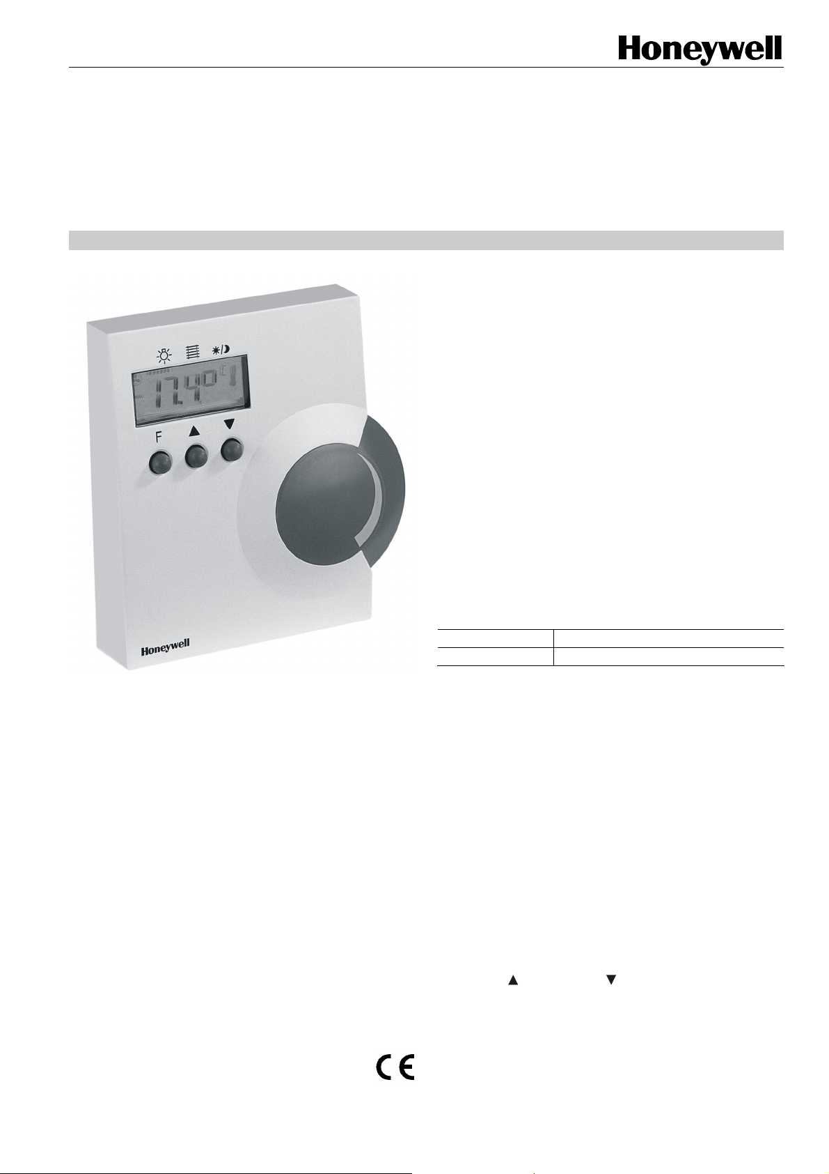
T7270B2009
WIRELESS WALL MODULE
HONEYWELL EXCEL 5000 OPEN SYSTEM
STANDARDS AND NORMS
The ZAPP System complies with CE and EN 300 220-1 and
EN 301 489-1.
IMPORTANT!
Use in Combination with Legacy Devices
The T7270B2009 ZAPP Wireless Wall Module is suitable for
use only with the W7070A2000 ZAPP Wireless Receiver. It
cannot communicate with (but is likewise unaffected by)
legacy devices (e.g. the W7070A1000).
NOTE: Do not attempt to teach-in both an RT7070A2008
TECHNICAL DATA
Batteries 1.5 V, type LR06, AA
Frequency 868.3 MHz (transmitter)
Fig. 1. T7270B2009
APPLICATION
The T7270B2009 Wireless Wall Module is designed for use in
wireless systems, and is suitable for use in conjunction with
the W7070A2000 ZAPP Wireless Receiver.
FEATURES
• Easy mounting, no wiring;
• All functions combined in a single, easy-to-use wall
module;
• Up to eight separate T7270B2009 wall modules can
simultaneously communicate with the W7070A2000 over
distances of approx. 30 meters and through two walls;
• Permits not only HVAC, but also light and sunblind
control;
• Fits seamlessly into XL10 / XL12 individual room control
systems.
OVERVIEW
Functions
In the operating mode, the T7270B2009 features the following
six basic functions:
LIGHT (this is the default function),
SUNBLINDS,
OCCUPANCY,
FAN,
SETPOINT OFFSET and
TEMPERATURE DISPLAY/TRANSMIT function.
Controls
The T7270B2009 features three control buttons and a large
setpoint wheel used (in the operating mode) to select
individual functions and to adjust their respective settings:
• the "function" button ("F"),
• the UP ("
• the setpoint wheel (for adjusting e.g. the value of the
INSTALLATION AND OPERATING INSTRUCTIONS
It is recommended that devices be kept at room
temperature for at least 24 hours before applying
power to allow any condensation resulting from low
shipping/storage temperatures to evaporate.
and a T7270B2009 to the same room.
") and DOWN (" ") buttons, and
temperature setpoint offset, etc.).
® U.S. Registered Trademark EN1B-0398GE51 R1207A
Copyright © 2007 Honeywell Inc. • All rights reserved
Page 2
T7270B2009 WALL MODULE
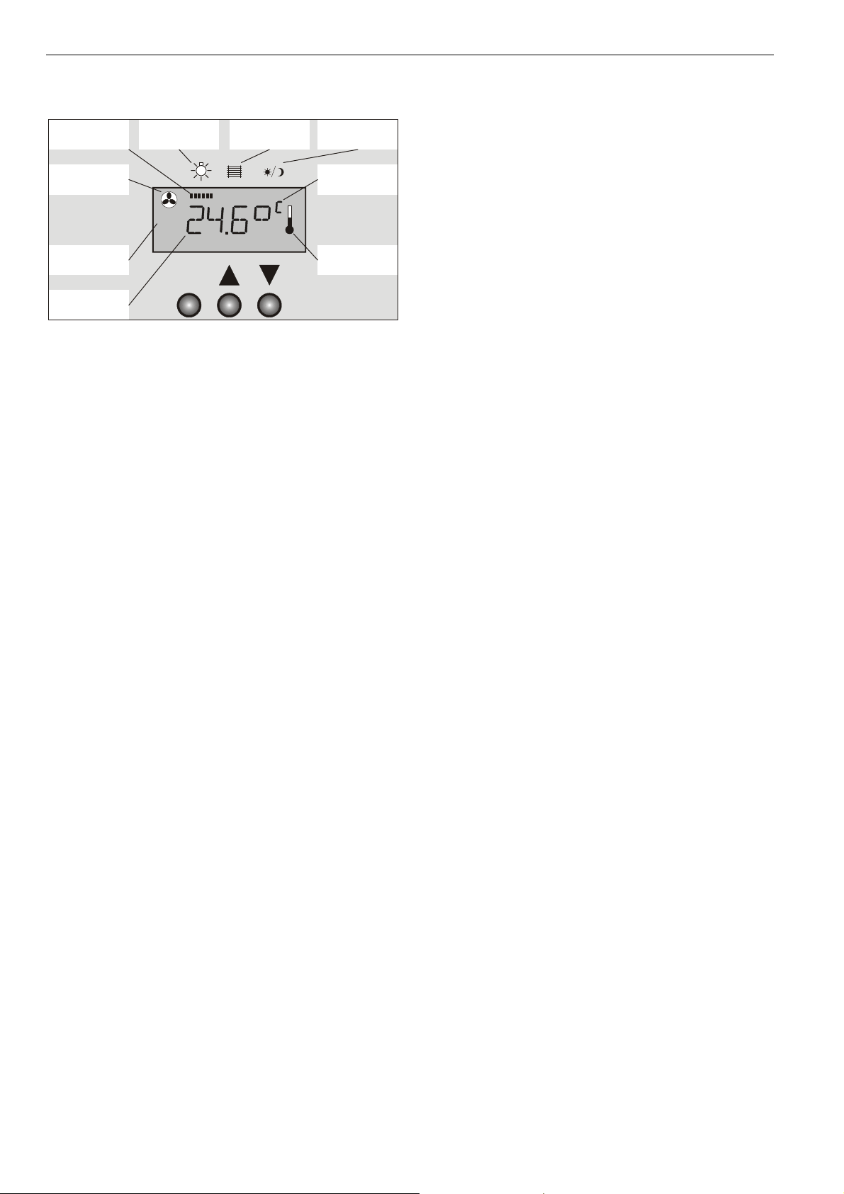
LCD Symbols and Printed Symbols
function
indication bar
fan
symbol
fan
mode
light
symbol
MANU
sunblind
symbol
occupancy
symbol
unit
thermometer
symbol
F
room
temperature
Fig. 2. Default Display
The function in effect at any particular moment is indicated by
the presence in the LCD of the function indication bar (see
Fig. 2), and a corresponding symbol; e.g. the fan symbol.
OPERATING MODE
Selecting Functions / Adjusting Settings
The user can select the LIGHT, SUNBLINDS, OCCUPANCY,
or FAN functions by pressing the "F" button, whereupon the
current room temperature will disappear from the LCD and be
replaced by the corresponding function symbol. The setting of
the selected function can then be adjusted as desired using
the UP button and the DOWN button.
To adjust a setting, press, as often as necessary (referred to
as "cycling"), the "F" button until the symbol representing the
desired function appears in the LCD. Once selected, this
symbol will be displayed for 4 sec. During this time, the user
can use the UP or DOWN buttons to adjust the setting. If
there is no user action for more than 4 sec, the function
symbol will disappear, and the T7270B2009 will revert to the
default display and the default function.
The SETPOINT OFFSET function is selected and its settings
adjusted using the large setpoint wheel located on the right
side of the T7270B2009 (see section "SETPOINT OFFSET
Function" below).
SETPOINT OFFSET Function
If the SETPOINT OFFSET function is selected (by rotating
the setpoint wheel), the current temperature setpoint offset,
accompanied by the degree symbol and corresponding temperature unit (°C or °F), will appear in the LCD.
NOTE: The SETPOINT OFFSET function can be configured
so as to be disabled whenever the user has used the
OCCUPANCY function to manually force the
controller into the "unoccupied" state and parameter
P8 (see page 6) has been set to 2 or 4. In this case,
the setpoint offset is fixed to 0.0 °.
Adjusting the Setting
The SETPOINT OFFSET function setting can be adjusted by
rotating the setpoint wheel clockwise or counterclockwise,
thus increasing or decreasing (respectively) the setpoint offset
over a range of max. -5...+5 K in steps of 0.5 K.
The setpoint offset range may be adjusted via parameter P4
(see page 6).
NOTE: A snowflake displayed in the lower right corner of the
LCD indicates that the T7270B2009 is transmitting
data. During transmission, the function keys are
disabled; you will thus have to wait approx. 1 sec
between e.g. switching a light ON and then OFF.
LIGHT Function
The LIGHT function is the default function (see section
“Default Function” page 4). The LIGHT function can be
selected by pressing the "F" button until the letters “”LI” are
displayed in the LCD and the function indication bar appears
underneath the light symbol imprinted on the housing.
NOTE: See also section "Default Function" on page 4.
Controlling a Single Light Group (P6:1)
If the T7270B2009 has been configured to control only a
single group of lights (see section "P6: Light Groups" on page
5), the LIGHT function settings are performed as described in
the following sections.
Pressing the UP Button
• Briefly pressing the UP button once turns the light group
ON and causes the word "ON" to appear in the LCD.
• Pressing the UP button for more than 2 sec turns the light
ON and starts dimming the light group. Once 0% is
reached, it starts brightening from 0% to 100%
(100%…0%…100%….). In the LCD, a vertical bar next to
the word "ON" moves continuously from the left to the
right. Releasing the UP button stops the process and
causes the LCD to revert to the default display mode.
Pressing the DOWN Button
• Briefly pressing the DOWN button once turns the light
group OFF and causes the word "OFF" to appear in the
LCD.
• Pressing the DOWN button for more than 2 sec turns the
light OFF and starts brightening the light group. “ON” is
displayed once the brightening starts. Brightening
continues until 100% is reached. Then it starts dimming
from 100% to 0% (0%…100%…0%….). In the LCD, a
vertical bar next to the word "ON" moves continuously
from the right to the left. Releasing the DOWN button
stops the process and causes the LCD to revert to the
default display mode.
NOTE: If, after dimming / brightening the light group, the
user uses the DOWN button to turn it OFF and subsequently back ON, it will be turned back ON at a
brightness level of 100%.
Controlling Two Light Groups (P6:2 and P6:3)
Dimming / brightening is not possible if the T7270B2009 has
been configured to control two light groups (see section "P6:
Light Groups" on page 5). In this case, it is possible only to
turn each group of lights ON or OFF.
The UP and DOWN buttons can be configured by setting
parameter P6 to 2 or 3.
EN1B-0389GE51 R1207A
2
Page 3

T7270B2009 WALL MODULE
NOTE: The UP and DOWN buttons can also be configured
by setting parameter P6 to 4 or 5 (special custom
models, only).
“UP” = ON and “DOWN” = OFF usage (P6:2)
Pressing the UP Button
Pressing the UP button will turn ON the two light groups as
follows:
• Pressing the UP button once turns ON light group 1, and
the characters "ON 1" appear in the LCD.
• Pressing the UP button twice turns ON light group 2, and
the characters "ON 2" appear in the LCD.
NOTE: The corresponding ON command is transmitted only
after the UP button is finally released. Thus, only one
light group can be turned ON/OFF at a time.
Pressing the DOWN Button
Pressing the DOWN button will turn OFF the two light groups
as follows:
• Pressing the DOWN button once turns OFF light group 1,
and the characters "OFF 1" will appear in the LCD.
• Pressing the DOWN button twice turns OFF light group 2,
and the characters "OFF 2" will appear in the LCD.
NOTE: The corresponding OFF command is transmitted
only after the DOWN button is finally released. Thus,
only one light group can be turned ON/OFF at a
time.
“UP” = Light 1 and “DOWN” = Light 2 usage (P6:3)
Pressing the UP Button for Light Group 1
Pressing the UP button the first time will turn ON light group
1, and the characters “ON 1” will appear in the LCD. Pressing
the UP button again will turn OFF light group 1, and the
characters “OFF 1” will appear in the LCD.
Pressing the DOWN Button for Light Group 2
The DOWN button has the same effect upon light group 2 as
the UP button upon light group 1.
Disabling the Light Function (P6:6)
The LIGHT function can be completely disabled by setting
parameter P6 to 6 (in this case, the SUNBLINDS function
then becomes the default function).
SUNBLINDS Function
The SUNBLINDS function can be selected by pressing the "F"
button until the corresponding function symbol – a stylized
representation of sunblinds (= = = =) – appears in the LCD
and the function indication bar appears underneath the
sunblind symbol imprinted on the housing.
The SUNBLINDS function can be configured via parameter
P5 ("sunblind runtime") as well as by setting parameter P9 to
1 ("no sunblind") or to 2 ("one sunblind").
NOTE: The value of the sunblind runtime must be the same
in the T7270B2009, the W7070A2000, and in the
connected controller (e.g. an XL12).
NOTE: The SUNBLINDS function can also be configured by
setting parameter P9 to 3 or 4 (special custom
models, only) as well as via parameter PB (special
custom models, only).
Refer to section “Configuration Parameters" on page 5 for
details.
Raising/Lowering One Set of Sunblinds (P9:2)
Pressing the UP Button
• Briefly pressing the UP button will completely raise the
sunblinds; in the LCD, the "sunblinds" symbol (= = = =)
moves upwards. Briefly pressing either the UP or the
DOWN button while the sunblinds are rising will stop the
sunblinds, and the LCD will revert to the default display.
• Pressing the UP button for more than 2 sec will raise the
sunblinds only as long as it remains pressed; in the LCD,
the "sunblinds" symbol (= = = =) moves upwards.
Pressing the DOWN Button
• Briefly pressing the DOWN button will completely lower
the sunblinds; in the LCD, the "sunblinds" symbol
(= = = =) moves downwards. Briefly pressing either the UP
or the DOWN button while the sunblinds are descending
will stop the sunblinds, and the LCD will revert to the
default display.
• Pressing the DOWN button for more than 2 sec will lower
the sunblinds only as long as it remains pressed; in the
LCD, the "sunblinds" symbol (= = = =) moves downwards.
When changing directions, the blinds will first stop, tilt, and
then move.
OCCUPANCY Function
If the OCCUPANCY function is selected (by pressing the "F"
button twice), one of the three following function symbols will
appear in the LCD:
• A crescent moon ("
override the occupancy state automatically established by
the controller and manually force it into the "unoccupied"
state, in which it will remain until overruled by a central
control unit or until the user himself changes this by again
invoking the OCCUPANCY function.
• A full sun ("
the occupancy state automatically established by the controller and manually force it into the "occupied" state, in
which it will remain until overruled by a central control unit
or until the user himself changes this by again invoking
the OCCUPANCY function.
• A half-sun ("
the occupancy state automatically established by the controller and manually force it into the "occupied" state for a
limited time (set using the controller's plug-in).
At the same time, the function indication bar will also appear
underneath the printed occupancy symbol. Thereafter, the
T7270B2009 will automatically revert to the default display,
i.e. it will no longer be apparent that the OCCUPANCY function had been invoked.
"), meaning that the user wishes to override
"), meaning that the user wishes to
"), meaning that the user wishes to override
3
EN1B-0398GE51 R1207A
Page 4

T7270B2009 WALL MODULE
NOTE: This design solution was chosen to avoid confusion
stemming from the fact that the T7270B2009 is not
capable of receiving (and therefore displaying) information from the W7070A2000 about the actual
occupancy state currently in effect.
Cycling with the UP button results in the following sequence
of displays: “crescent moon”, then nothing, then “half-sun”,
then “full sun”. Cycling with the DOWN button reverses the
sequence.
NOTE: The OCCUPANCY function can be disabled (see
section "PA: Disable/Enable OCCUPANCY
Function" on page 6). When cycling with the "F"
button, this function and the corresponding display in
the LCD sequence will then be unavailable to the
user.
FAN Function
If the FAN function is selected (by pressing the "F" button
three times), the corresponding function symbol – a stylized
fan (
) – will appear in the LCD, accompanied by either
• the "AUTO" symbol, meaning that the user does not wish
to override the fan setting automatically established by the
controller, or
• the "MANU" symbol, meaning that the user wishes to
override the fan setting automatically established by the
controller, together with the numeral "0", "1", "2", or "3"
(representing the fanspeeds).
Cycling with the UP button results in the following sequence
of displays: "AUTO", then "MANU 0", then "MANU 1", then
"MANU 2", then "MANU 3". Cycling with the DOWN button
reverses the sequence.
After the selection has been completed, the “AUTO” / “MANU”
symbol will become part of the default display.
NOTE: The FAN function can be configured so as to be
disabled whenever the user has manually forced the
controller into the "unoccupied" state and parameter
P8 (see page 6) has been set to 3 or 4. When
cycling with the "F" button, the FAN function and the
corresponding display in the LCD sequence will then
be unavailable to the user. If the FAN function is not
available, check parameter P8 to see if it has been
disabled and/or change the occupancy state.
NOTE: The FAN function can be configured for “no fan”,
“ON/OFF fan”, “2-speed fan” or “3-speed fan” via
parameter P3 (see section "P3: Fan" on page 5). If
the fan does not work as expected, check the
settings of parameter P3.
Default Display and Default Function
If there is no user action for more than 4 sec, the
T7270B2009 will automatically revert to the default display
and the default function.
Default Display
In the default display (see for example Fig. 2), the current
room temperature (in °C or °F, as desired) with a resolution of
one-tenth of a degree is shown in the LCD. Further, the
temperature symbol – a stylized thermometer ("
shown.
") – is also
Default Function
The LIGHT function is the default function. Thus, the user can
adjust the setting (i.e. dim, brighten, or turn a light group
ON/OFF) simply by using the UP and DOWN buttons, and
without having to cycle through the other function symbols.
Power-Up / Teach Commands
After power-up, an LCD test will be carried out (i.e. all LCD
segments will be activated for approx. 1 sec).
Fig. 3. LCD test after power-up
After that, two teach commands will be triggered. Please
refer to W7070A2000 Receiver – System Engineering
(Product Literature No.: EN0B-0286GE51) on how to perform
a teach-in. A special LCD sequence “t 1”, then “t 2” will be
shown while the given teach command is being transmitted.
Checking the Software Version and
Transmitting Teach Commands
To check the version of the software currently loaded in the
T7270B2009, the user must press the "F" button and the
DOWN button simultaneously for approx. 5 sec.
After the LCD test is then automatically performed, the name
of the current software version in the T7270B2009 (e.g.
"1.03") will appear in the LCD and a special LCD sequence
“t 1”, then “t 2” will be shown while the given teach command
is being transmitted.
EN1B-0389GE51 R1207A
4
Page 5

T7270B2009 WALL MODULE
CONFIGURATION MODE
By configuring the T7270B2009, the user can alter its functions / displays to better reflect the actual operating environment (e.g. the presence of a fan, the number of speed levels
it has, the number of light groups, etc.) in which it is used. To
configure the T7270B2009, proceed as follows:
1. Press the "F" button and, while still pressing it, press the
UP button (for at least 5 sec).
RESULT: "P-:--" appears in the LCD, indicating that the
T7270B2009 is now ready for configuration.
2. Release both buttons. Then press the "F" button again
and, while still pressing it, rotate the setpoint wheel to the
desired parameter (e.g. PA).
RESULT: The LCD cycles through the various different
parameters (P1 through PB) together with their current
configurations.
3. Release the "F" button and rotate the setpoint wheel to
select the parameter value (e.g. "1" or "2").
4. Confirm your selection by pressing the UP button.
5. You may now continue configuring – or leave the configuration mode and permanently store your configurations
by pressing the DOWN button.
Configuration Parameters
P1: Temperature Unit
With this parameter, the user can configure the unit (°C or °F)
in which the room temperature and (relative) temperature
setpoint offset are displayed:
• P1:1 → Temperatures are displayed in °F.
• P1:2 → Temperatures are displayed in °C. This is the
default configuration.
P2: Default Display
With this parameter, the user can configure the default
display:
• P2:1 → The default display shows the setpoint offset.
• P2:2 → The default display shows the current room
temperature. This is the default configuration.
P3: Fan
With this parameter, the user can configure the fan (i.e.
establish whether a fan is present and how many speed levels
it has) as well as enable/disable the FAN function:
• P3:1 → No fan is present in the room. This configuration
disables the FAN function.
• P3:2 → An ON/OFF fan is present. This configuration
enables the FAN function.
• P3:3 → A 2-speed fan is present. This configuration
enables the FAN function.
• P3:4 → A 3-speed fan is present. This is the default
configuration.
P4: Temperature Setpoint Offset Limits
With this parameter, the user can configure the range over
which the temperature setpoint offset can be adjusted.
• The max. range is -5...+5 K. The min. range is -1...+1 K.
• The range can be widened/narrowed with the setpoint
wheel in steps of 1 K.
• The default configuration is -3…+3 K.
P5: Sunblind Runtime
With this parameter, the user can configure the time during
which the sunblinds rise/descend.
• The runtime has a range of 1...99 s.
• This range can be widened/narrowed with the setpoint
wheel in steps of 1 s.
• The default runtime is 60 s.
P6: Light Groups
With this parameter, the user can configure whether only a
single group of lights or two groups of lights are present.
• P6:1 → Only a single group of lights is present.
• P6:2 → Two groups of lights are present. Pressing the UP
button turns ON light groups 1 and 2 and pressing the
DOWN button turns OFF light groups 1 and 2.
• P6:3 → Two groups of lights are present. Pressing the UP
button turns ON/OFF light group 1 and pressing the
DOWN button turns ON/OFF light group 2. This is the
default configuration.
• P6:4 and P6:5 are currently used with special custom
models, only. Do not set these parameters.
• P6:6 → No LIGHT function is disabled and the
SUNBLINDS function becomes the default function
P7: Room Temperature Correction Value
With this parameter, the user can correct the room temperature value displayed in the LCD and transmitted to the
W7070A2000 Wireless Receiver.
• A value of 50 means "no change", i.e. the temperatures
measured by the T7270B2009 are displayed/transmitted
without correction. This is the default configuration.
• Values of 49, 48, 47, etc. mean that the temperatures
measured by the T7270B2009 are displayed/transmitted
with a correction of -0.1 K, -0.2 K, -0.3 K, etc.
• Values of 51, 52, 53, etc. mean that the temperatures
measured by the T7270B2009 are displayed/transmitted
with a correction of +0.1 K, +0.2 K, +0.3 K, etc.
5
EN1B-0398GE51 R1207A
Page 6

T7270B2009 WALL MODULE
P8: Unoccupied Room
With this parameter, the user can configure the SETPOINT
OFFSET function and the FAN function to be enabled /
disabled whenever the user has used the OCCUPANCY
function to manually force the controller into the "unoccupied"
state:
• P8:1 → The FAN function and the SETPOINT OFFSET
function are both enabled. This is the default con-
figuration.
• P8:2 → The FAN function is enabled and the SETPOINT
OFFSET function is disabled.
• P8:3 → The FAN function is disabled and the SETPOINT
OFFSET function is enabled.
• P8:4 → The FAN function and the SETPOINT OFFSET
function are both disabled.
P9: Disable/Enable SUNBLINDS Function
With this parameter, the user can enable/disable the
SUNBLINDS function:
• P9:1 → There are no sunblinds present in the room. This
configuration disables the SUNBLINDS function.
• P9:2 → One set of sunblinds is present. This con-
figuration enables the SUNBLINDS function. This is the
default configuration.
• P9:3 and P9:4 are currently used with special custom
models, only. Do not set these parameters.
PA: Disable/Enable OCCUPANCY Function
With this parameter, the user can enable/disable the
OCCUPANCY function:
• PA:1 → This disables the OCCUPANCY function.
• PA:2 → This enables the OCCUPANCY function.
• PA:3 → This partially disables the OCCUPANCY func-
tion. Specifically, the user can then no longer manually
force the controller into the permanent "unoccupied"
("
") or "occupied" (" ") states. However, he can still
manually force the controller into the "occupied" state for
a limited time ("
PB and PC
Currently used with special custom models, only. Do not set
these parameters.
• PB: Sunblind Grouping (default: 1 sunblind group)
• PC: Sunblind Short/Long Button Press 1…60 sec (default:
99 = disabled)
"). This is the default configuration.
Set-Up
Because of interference from other devices and the building
structure, it is not possible to exactly define the wireless
transmission range. See W7070A2000 Receiver Installation
Instructions (EN1B-0396GE51) for information on installing
wireless systems.
MOUNTING
Mount the T7270B2009 on an inside wall approximately 54 in.
(1.3 m) from the floor (or as specified on the installation
drawings) to allow exposure to the average zone temperature.
Do not mount the T7270B2009 on an outside wall, on a wall
containing water pipes, or near air ducts. Avoid locations that
are exposed to discharge air from registers or radiation from
lights, appliances, or the sun.
Fig. 4. Mounting
Removing the Housing Cover
The T7270B2009 comes with a sub-base that mounts
separately for ease of installation. The housing cover can be
removed as follows (see also Fig. 5):
1. Insert the tip of an awl or a similar narrow, pointed
implement into the small hole in the latch.
2. Pry off the cover.
EN1B-0389GE51 R1207A
Fig. 5. Opening the housing
6
Page 7

Batteries
The batteries (two standard alkaline AA or LR6 or AM3
batteries) have a min. lifetime of 2 years.
Inserting Batteries
1. Open the housing (see Fig. 5) by pressing the snap-on
lock on the bottom of the housing while removing the
cover.
2. Remove any discharged batteries, if necessary.
NOTE: Batteries should not be disposed of in the household
garbage. You may be required by local law to
dispose of discharged batteries in a certain manner.
Always replace both batteries. Use only 1.5 V
mignon batteries of the type AA or LR6 or AM3.
Ensure that the polarity is correct (see Fig. 6 on
page 8).
3. Insert the supplied (or replacement) batteries into the
battery compartment.
Low Batteries
If the batteries are nearing the end of their useful life, the
word "BATT" will appear in the LCD. This means that the
batteries must be replaced (see section "Inserting Batteries"
above).
T7270B2009 WALL MODULE
7
EN1B-0398GE51 R1207A
Page 8

T7270B2009 WIRELESS WALL MODULE
DIMENSIONS
86
100
68
97
99
85
F
104
2
Honeywell
30
Fig. 6. T7270B2009, dimensions in mm
Honeywell
Manufactured for and on behalf of the Environmental and Combustion Controls Division of Honeywell Technologies Sàrl, Ecublens, Route du Bois 37, Switzerland by its Authorized Representative:
Automation and Control Solutions
Honeywell GmbH
Böblinger Straße 17
D-71101 Schönaich
Phone: (49) 7031 63701
Fax: (49) 7031 637493
http://ecc.emea.honeywell.com
Subject to change without notice. Printed in Germany
This document is definitive for the enclosed product and replaces all previous publications.
Honeywell Inc. hereby declares that this device complies with the basic requirements and other relevant regulations of guideline 1999/5/EC. The declaration of
conformity of the product can be requested from the manufacturer.
Note to non-E.U. countries: This product may only be used if operation in the 868 MHz frequency band is permissible.
EN1B-0398GE51 R1207A
 Loading...