

Page 1
1
2
HONEYWELL EXCEL 5000 OPEN SYSTEM
T7270A2001/2019
WIRELESS WALL MODULES
INSTALLATION AND OPERATING INSTRUCTIONS
Scope of Delivery
One T7270A2001 or one T7270A2019
Two AA batteries
STANDARDS AND NORMS
The ZAPP System complies with CE and EN 300 220-1 and
EN 301 489-1.
IMPORTANT!
It is recommended that devices be kept at room
temperature for at least 24 hours before applying
power to allow any condensation resulting from low
shipping/storage temperatures to evaporate.
Use in Combination with Legacy Devices
The T7270A2001/T7270A2019 ZAPP Wireless Wall Modules
are suitable for use only with the W7070A2000 ZAPP Wireless Receiver. They cannot communicate with (but are likewise unaffected by) legacy devices (e.g. the W7070A1000).
COMMISSIONING
See the W7070A2000 ZAPP Receiver Installation Instructions
(EN1B-0396GE51) for information on installing wireless
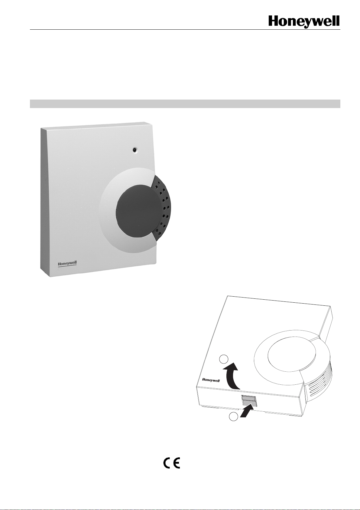
Fig. 1. T7270A2001
systems.
APPLICATION
The T7270A2001/T7270A2019 ZAPP Wireless Wall Modules
are used for intelligent room temperature control.
• The T7270A2019 ZAPP Wireless Wall Module measures
the room temperature and transmits the measured values
to the W7070A2000 ZAPP Wireless Receiver.
• The T7270A2001 ZAPP Wireless Wall Module measures
the room temperature and transmits the measured values
to the W7070A2000 ZAPP Wireless Receiver.
Additionally, the T7270A2001 allows the room setpoint
temperature to be adjusted.
The T7270A2001/T7270A2019 transmit the data to the
W7070A2000 at 868.3 MHz.
Additional Features of T7270A2001
The T7270A2001 ZAPP Wireless Wall Module has the
following functions (in addition to those of the T7270A2019):
Adjustment wheel at which you can change the room tem-
perature setpoint directly. The adjustment range amounts
to ± 12 °C, starting from the basic value of 20 °C (in
position 0).
® U.S. Registered Trademark EN1B-0397GE51 R1207A
Copyright © 2007 Honeywell Inc. • All rights reserved
Fig. 2. Removing the housing cover
Page 2
►
Remove the housing cover of the T7270A2001 /
T7270A2019 (see Fig. 2
).
T7270A2001/2019 WIRELESS WALL MODULE
Installation
►
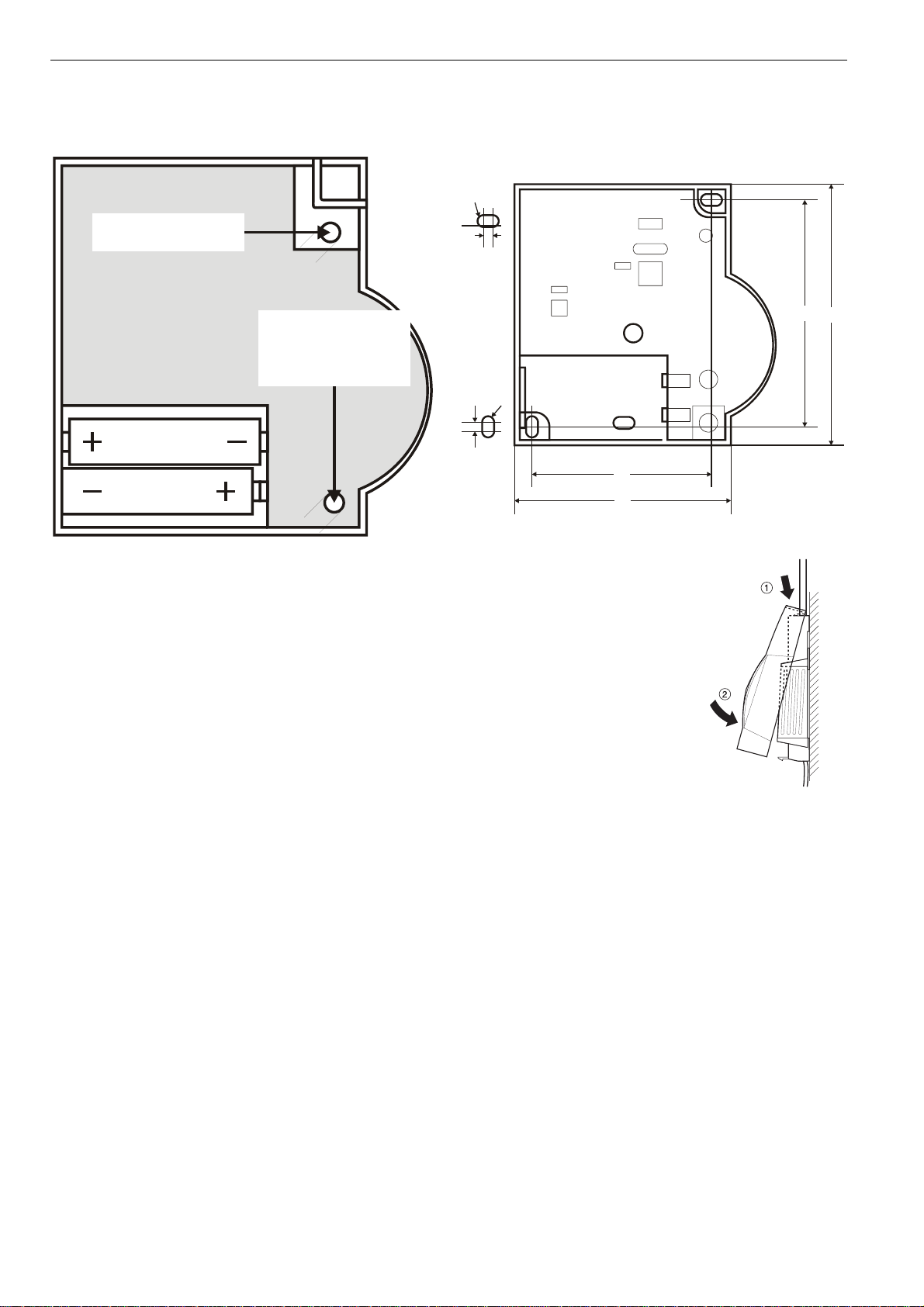
Remove the batteries.
►
Mark the drill holes according to the drilling template (see
Fig. 4).
R2
RED LED
TEACH-IN
BUTTON
Fig. 3. Battery polarity and “Teach-In” button
►
Insert the supplied AA batteries with the correct battery
polarity (see Fig. 3). If the red LED of the T7270A2001 /
T7270A2019 flashes, this means that the batteries must be
replaced (see section "Changing Batteries").
►
Place the T7270A2001/T7270A2019 at the installation site,
but do not install it yet.
►
Allocate the corresponding temperature zone to the
T7270A2001/T7270A2019 ─ see System Engineering
(EN0B-0286GE51) for information on the "teach-in"
procedure.
Failed Teach-In
If the teach-in has failed:
►
Improve the data transfer (see below).
►
Repeat the teach-in.
Improving the data transfer
►
When selecting the operating site of each device, ensure
that the distance to radio devices such as radio
headphones, cordless phones, etc. according to the DECT
standard amounts to at least 1 m.
►
Do not install the devices over metallic wall connecting
sockets and at least 30 cm away from the cover of the heat
generator.
►
Correct the installation site of the devices, if necessary.
Please see also System Engineering (EN0B-0286GE51).
De-Teaching Devices
For more information about de-teaching individual (or all)
devices, please see System Engineering (EN0B-0286GE51).
4
R2
4
►
Drill the holes.
►
Screw on the wall module.
►
Re-insert the batteries.
►
Place the housing cover in
position above and snap it down
(see Fig. 5).
Fig. 4. Drilling scheme (in mm)
68
82
Fig. 5. Replacing
housing cover
86
99
EN1B-0397GE51 R1207A 2
Page 3

T7270A2001/2019 WIRELESS WALL MODULE
SPECIAL FEATURES OF T7270A2001
Operation
The room setpoint temperature can be set easily at the
T7270A2001 using its adjustment wheel. The adjustment
range amounts to ± 12 °C, starting from the basic value of
20 °C (in position 0).
Fig. 6. T7270A2001
►
Select the desired change of the preset temperature at the
adjustment wheel (1) (see Fig. 6) (scale in °C).
Limiting the Adjustment Range
You can limit the setting range that can be used at the
adjustment wheel.
►
Remove the housing cover (see Fig. 2).
Fig. 7. Limiting the adjustment range
►
Place the two small pins into the holes of the adjustment
wheel in order to limit the adjustment range (see Fig. 7).
Orientate yourself on the basis of the inner scale:
In Fig. 7, the pins are inserted so that the adjustment wheel
can only be adjusted by ±3 °C around the zero point.
►
Turn the adjustment wheel clockwise until it stops.
►
Check whether the adjustment wheel is in the position
shown in Fig. 6.
►
If appropriate, put the adjustment wheel back in, rotated by
180°, until it has the position shown.
►
Turn the adjustment wheel to Position 0.
►
Place the housing cover in position above and snap it down
(see Fig. 5).
3
EN1B-0397GE51 R1207A
Page 4

T7270A2001/2019 WIRELESS WALL MODULE
CHANGING BATTERIES
Change the batteries if the red LED of the room temperature
sensor flashes and the device is not in test mode.
►
Remove the housing cover of the T7270A2001 /
T7270A2019 (see Fig. 2).
►
Remove the batteries.
Dispose of the batteries according to the
local statutory requirements and not
together with the usual domestic refuse.
Always replace both batteries together.
Only use 1.5 V batteries of the type LR06, AA.
►
Insert the new batteries with the correct polarity into the
battery compartment (see Fig. 3).
►
Place the housing cover on at the top and latch it in
downwards (see Fig. 5).
TROUBLESHOOTING
Problem Cause Remedy
Teach-in failed
No measured
data at
W7070A2000
Batteries
inserted
incorrectly
Radio
connection
failure
Batteries
inserted
incorrectly
Radio
connection
failure
Module not
assigned or
assigned
incorrectly
►
Insert the batteries
correctly.
►
Eliminate interference
sources (metal, wireless
devices).
►
Correct installation site.
►
Repeat the teach-in.
►
Insert the batteries
correctly.
►
Eliminate interference
sources (metal, wireless
devices).
►
Repeat the teach-in.
►
Repeat the teach-in.
►
Check the assignment.
If appropriate, repeat.
TECHNICAL DATA
Batteries 1.5 V, type LR06, AA
Frequency 868.3 MHz (transmitter)
WEEE DIRECTIVE 2002/96/EC
►
At the end of the product life, dispose of
the packaging and product in a
corresponding recycling center.
►
Do not dispose of the unit with the usual
domestic refuse.
►
Do not burn the product.
Manufactured for and on behalf of the Environmental and Combustion Controls Division of Honeywell Technologies Sàrl, Ecublens, Route du Bois 37, Switzerland by its Authorized Representative:
Honeywell GmbH
Böblinger Straße 17
71101 Schönaich, Germany
Tel.: (++49) (0) 7031 637 01
Fax: (++49) (0) 7031 637 493
http://europe.hbc.honeywell.com
Subject to change without notice. Printed in Germany
This document is definitive for the enclosed product and replaces all previous publications.
Honeywell Inc. hereby declares that this device complies with the basic requirements and other relevant regulations of guideline 1999/5/EC. The declaration of
conformity of the product can be requested from the manufacturer.
Note to non-E.U. countries: This product may only be used if operation in the 868 MHz frequency band is permissible.
EN1B-0397GE51 R1207A
 Loading...