

Page 1
T7200D,E Series 2000 Commercial
Microelectronic Thermostats
INSTALLATION INSTRUCTIONS
APPLICATION
The T7200D,E Thermostats provide electronic control of
24 Vac commercial single-zone heating, ventilating and air
conditioning (HVAC) equipment. The T7200 is field
configurable for automatic or manual changeover between
heating and cooling. The system and fan selections are
made by keyboard entry. All T7200 Thermostats require a
common wire to supply power.
RECYCLING NOTICE
If this control is replacing a control that contains
mercury in a sealed tube, do
control in the trash.
Contact your local waste management authority for
instructions regarding recycling and the proper
disposal of the old thermostat.
NO
not
place your old
NO
INSTALLATION
When Installing this Product…
1. Read these instructions carefully. Failure to follow
the instructions can damage the product or cause a
hazardous condition.
2. Check the ratings given in the instructions and on
the product to make sure the product is suitable for
your application.
3. Installer must be a trained, experienced service
technician.
4. After completing installation, use these instructions
to check out the product operation.
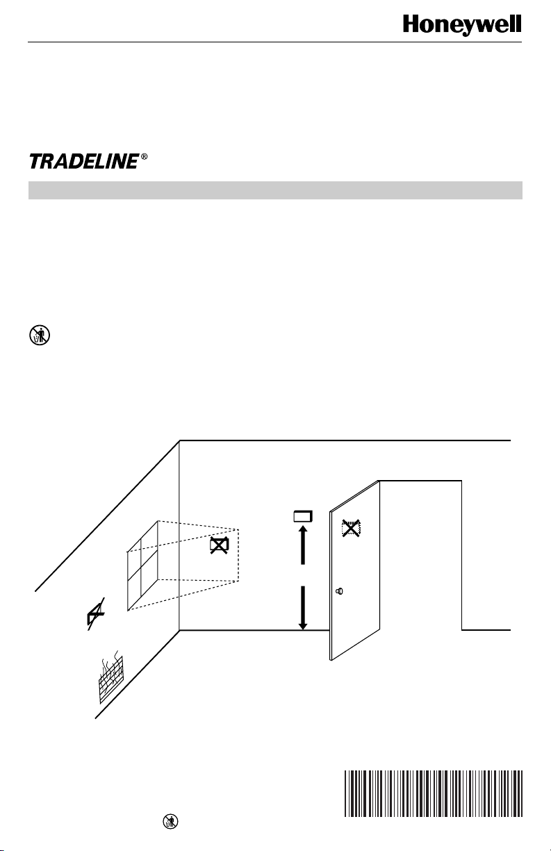
Location
Install the thermostat about 5 ft (1.5m) above the floor in
an area with good air circulation at average temperature.
See Fig. 1.
YES
5 FEET
(1.5 METERS)
NO
Fig. 1. Typical location of thermostat.
® U.S. Registered Trademark
Copyright © 1998 Honeywell Inc. • • All Rights Reserved
X-XX UL
M4823A
62-0128-2
Page 2
T7200D,E SERIES 2000 COMMERCIAL MICROELECTRONIC THERMOSTATS
Do not install the thermostat where it can be affected by:
— drafts, or dead spots behind doors and in corners.
— hot or cold air from ducts.
— radiant heat from sun or appliances.
— concealed pipes and chimneys.
— unheated (uncooled) areas such as an outside wall
behind the thermostat.
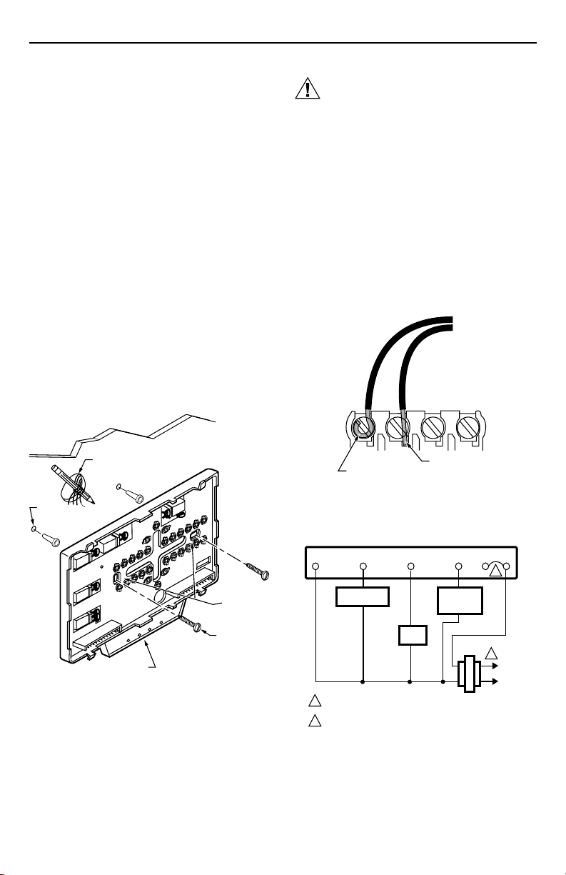
Mounting Wallplate
The wallplate mounts horizontally on the wall or on a
2 in. x 4 in. wiring box. Position the wallplate horizontally
on the wall or on a 2 in. x 4 in. wiring box.
1. Position and level the wallplate (for appearance
only). The thermostat functions properly even when
not level.
2. Use a pencil to mark the mounting holes. See Fig. 2.
3. Remove the wallplate from the wall and drill two
3/16 inch (4.8 mm) holes in the wall (if drywall) as
marked. For firmer material such as plaster or wood,
drill two 7/32 inch (5.5 mm) holes. Gently tap
anchors (provided) into the drilled holes until flush
with the wall.
4. Position the wallplate over the holes, pulling wires
through the wiring opening.
5. Loosely insert the mounting screws into the holes.
6. Tighten mounting screws.
WALL
CAUTION
Electrical Shock Hazard.
Power source can cause electrical shock.
Disconnect power before wiring to prevent
electrical shock or equipment damage.
1. Loosen the terminal screws on the wallplate and
connect the system wires. See Fig. 3.
IMPORTANT
Use 18-gauge, solid-conductor color-coded
thermostat cable for proper wiring. If using
18-gauge stranded wire, do not use more than
ten wires. Do not use larger than 18-gauge wire.
2. Securely tighten each terminal screw.
3. Push excess wire back into the hole.
4. Plug the hole with nonflammable insulation to
prevent drafts from affecting the thermostat.
WIRES
THROUGH WALL
WALL
ANCHORS
(2)
MOUNTING
HOLES
MOUNTING
SCREWS
LEDS
Fig. 2. Mounting the wallplate.
WIRING WALLPLATE
All wiring must comply with local electrical codes and
ordinances. Follow equipment manufacturer wiring
instructions when available. Refer to Fig. 4 and 5 for
typical hookups. A letter code is located near each
terminal for identification.
62-0128—2
M10237
FOR STRAIGHT
FOR WRAPAROUND
INSERTION STRIP
7/16 IN. (11 MM).
INSERTION STRIP
5/16 IN. (8 MM).
Fig. 3. Proper wiring technique.
THERMOSTAT
FAN
RELAY
HEATING
RELAY OR
VALVE COIL
COMPRESSOR
CONTACTOR
1
POWER SUPPLY. PROVIDE DISCONNECT MEANS AND
OVERLOAD PROTECTION AS REQUIRED.
2
JUMPER RC AND RH FOR SINGLE TRANSFORMER SYSTEMS.
Fig. 4. Typical hookup of T7200D in single-stage
heating and cooling conventional system.
2
M4826
RCRHXY1GW1
2
1
L1
(HOT)
L2
M4942A
Page 3

T7200D,E SERIES 2000 COMMERCIAL MICROELECTRONIC THERMOSTATS
THERMOSTAT
RXYGO
FAN
RELAY
COOL
CHANGEOVER
VALVE
1
L1
(HOT)
L2
M4943A
COMPRESSOR
CONTACTOR
1
POWER SUPPLY. PROVIDE DISCONNECT MEANS AND
OVERLOAD PROTECTION AS REQUIRED.
Fig. 5. Typical hookup of T7200E in single-stage heat
Mounting Thermostat on Wallplate
The thermostat mounts on the wallplate after it is installed.
1. Engage the tabs at the top of the thermostat and
wallplate. See Fig. 6.
2. Press the lower edge of the case to latch.
NOTE: To remove the thermostat from the wall, first pull
out at the bottom of the thermostat; then remove
the top.
pump system.
SETTINGS
Using Thermostat Keys
The thermostat keys are used to:
• set current time and day,
• program times and setpoints for heating and cooling,
ENTER UNOCCUPIED
ENTER OCCUPIED
PROGRAM MODE
PROGRAM MODE
SET CURRENT DAY OR
PROGRAM DAY
• override the program temperatures,
• display present setting,
• set system and fan operation,
• configure Installer Setup,
• check Installer System Test.
See Fig. 7 for thermostat key information.
A.
ENGAGE TABS AT TOP OF THERMOSTAT AND SUBBASE OR WALLPLATE.
B.
PRESS LOWER EDGE OF CASE TO LATCH.
M4824A
Fig. 6. Mounting thermostat on wallplate.
SET OCCUPIED
TEMPERATURE
SETPOINTS
SET UNOCCUPIED TEMPERATURE
SETPOINTS AND SCROLLS
THROUGH INSTALLER SETUP
AND SYSTEM TEST
RETURNS TO
NORMAL
OPERATIONS
SET OVERRIDE
TEMPERATURE
OFFSET AND
ACTIVATE
TEMPORARY
OVERRIDE
ENTER HOLD MODE
Run
Program
Temporary
Occupied
Continuous
Unoccupied
SET CURRENT
DAY AND TIME
CLEAR PROGRAM PERIOD
Clear
AM
Copy
Mon
Occupied
System Fan
Heat
Set Program Set Temperature Change
Unoccupied
Occupied
Start Time Day
Start Time
Set Current
Day/Time
Start Time
Room
Auto
Occupied
Temp
System Fan
SELECT
SYSTEM
OPERATION
COPY ONE
PROGRAMMED DAY
TO ANOTHER DAY
Unoccupied
Temp
Heat/Cool
Settings
Time/Temp
SELECT FAN
OPERATION
Fig. 7. Thermostat key locations and descriptions.
3
INCREASE
TEMPERATURE
OR TIME SETTING
DECREASE
TEMPERATURE
OR TIME SETTING
CHANGE BETWEEN HEATING
AND COOLING SETPOINTS
AND SCROLLS BACKWARDS
THROUGH INSTALLER SETUP
NUMBERS AND SYSTEM TEST
M10233A
62-0128—2
Page 4
T7200D,E SERIES 2000 COMMERCIAL MICROELECTRONIC THERMOSTATS
Em Ht
Set Day/Time
Setting System and Fan (select models)
The system default setting is Heat. The fan default is set
so the fan operates continuously in the Occupied and
Recovery modes and with the heating or cooling equipment in the Unoccupied mode. Use the System and Fan
keys to change the settings.
The system settings are:
Heat: Thermostat controls the heating.
Off: Both the heating and cooling are off.
Cool: Thermostat controls the cooling.
Auto: Thermostat automatically changes between
heating and cooling operation depending on the
indoor temperature.
The fan settings are:
On: Fan operates continuously.
Auto: Equipment controls the fan in the Unoccupied
mode. The Intelligent Fan™ operation (Installer
Setup number 17) offers three choices for the fan
operation in Occupied mode:
— fan turns on only when there is a call for heating
or cooling,
— fan operates continuously in Occupied mode,
— fan is on continuously in Occupied and recovery
modes.
Setting Temperature
Refer to Table 1 for the default temperature setpoints. See
Owners Guide, form number 63-4356, for complete
instructions on changing the setpoints.
Table 1. Default Temperature Setpoints.
Control Occupied Unoccupied
Heating 70°F (21°C) 55°F (13°C)
Cooling 78°F (25.5°C) 90°F (32°C)
INSTALLER SETUP
NOTE: For most applications, the thermostat factory-
settings do not need to be changed. Review the
factory-settings in Table 2 and if no changes are
necessary, go to the Installer System Test
section.
The Installer Setup is used by the installer to customize
the thermostat to specific systems. Installer Setup
numbers are listed in Table 2. The table includes all the
configuration options available.
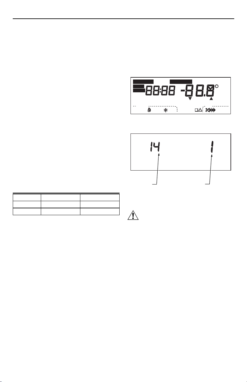
A combination of key presses are required to use the
Installer Setup feature.
— To enter the Installer Setup mode, press and hold the
Heat/Cool Settings key while pressing both the
increase ▲ and decrease ▼ keys until the first
number is displayed. All display segments appear for
approximately three seconds before the number is
displayed. See Fig. 8 and 9.
— To advance to the next Installer Setup number, press
the Unoccupied Temp key.
— To return to a previous Installer Setup number, press
the Heat/Cool Settings key.
— To change a setting, use the increase ▲ or decrease
▼ key.
— To exit the Installer Setup, press the Run Program
key. The Installer Setup is automatically exited if no
key presses are made for four minutes.
PM
AM
Recovery
In
Lo
Med
Wait
Temporary Setting Enrg
Room
%Humid
Cool
Auto
Remote
Only
On
Duct
Heat
Hi
Sav
Auto
M4916
Set Program
Em Ht
Aux Ht
Comm
Mon
TueWedThuFriSatSun
Un
Occupied 12 Override
System Fan
Off Auto
Heat
Em
Start Time
Cool
Set Day/Time
Fig. 8. LED display of all segments.
INSTALLER SETUP
NUMBER DISPLAY
(COLUMN 2
OF TABLE 2)
FACTORY SETTING
OR OTHER CHOICE
DISPLAY (COLUMN 3
OR 5 OF TABLE 2)
M10238B
Fig. 9. Installer Setup number and setting display.
Installer Setup numbers are listed in Table 2.
CAUTION
Possible Equipment Damage.
Fan must be running when system is
operating.
Configure heat pump and electric heat systems in
Installer Setup 2 to prevent equipment damage
caused by the system running without the fan.
IMPORTANT
Only configurable numbers are shown on the
device. Example: If the thermostat does not have
a system key, Installer Setup Number 12 will not
be displayed. Review Table 2 factory settings
and mark any desired changes in the Actual
Setting column. When Installer Setup is complete, review the settings to confirm that they
match the system.
62-0128—2
4
Page 5

T7200D,E SERIES 2000 COMMERCIAL MICROELECTRONIC THERMOSTATS
Table 2. Thermostat Installer Setup Options.
Installer Setup
Number
(Press
Select
Unoccupied
Temp key
to change)
Factory Setting
Display Description Display Description
Not used. 1 — — — — —
a
Fan operation
(T7200D only).
Degree
temperature
display.
Intelligent Fan™
operation.
Keypad lockout
level (keypad
lockout is
enabled and
disabled by dip
switch 1 on
thermostat
back).
O/B Operation
(T7200E only).
Minimum offtime for the
compressor.
Temperature
display
adjustment.
a
Number 2 must be set to 1 to extend fan operation.
b
Some models may not have this feature.Table 2.
20Conventional applica-
14 0 Temperature is
17 2 Fan operates
25 0 No lockout. 1 or 2 1—Lockout all keys on
b
29 0 0—Energize in Cool
33 4 4-minute minimum
37 0 No difference in
tions where
equipment controls
fan operation in heat
mode.
displayed in °F.
continuously in
Occupied and
Recovery mode. Fan
operates with call for
heating or cooling in
Unoccupied mode.
mode.
off-time for the
compressor.
displayed
temperature and
actual room
temperature.
1 Electric heat applications
1 Temperature is displayed
0 or 1 0—Fan only operates with
11—Energize in Heat Mode.
0, 1, 2, 3
or 5
1 thru 6 1—Display adjusts to 1°F
Other Choices
(Press ▲ or ▼ key to change)
where thermostat controls
fan operation in heat mode.
in °C.
calls for heating or cooling
in Occupied and
Unoccupied modes.
1—Fan operates
continuously in Occupied
mode. Fan operates with
calls for heating or cooling
in Unoccupied mode.
thermostat except system
and fan settings, temporary
setpoint; clock and day
adjustments.
2—Lockout all keys except
set Current Day/Time,
increase ▲ and decrease
▼ keys.
3—Lockout all keys except
Temporary Occupied, Set
Current Day/Time (for
clock, day adjustments).
Minimum number of minutes
(0 thru 5) the compressor will
be off between calls for the
compressor.
(0.6°C) higher than actual
room temperature.
2—Display adjusts to 2°F
(1.1°C) higher than actual
room temperature.
3—Display adjusts to 3°F
(1.7°C) higher than actual
room temperature.
4—Display adjusts to 1°F
(0.6°C) lower than actual
room temperature.
5—Display adjusts to 2°F
(1.1°C) lower than actual
room temperature.
6—Display adjusts to 3°F
(1.7°C) lower than actual
room temperature.
Actual
Setting
(continued)
5
62-0128—2
Page 6

T7200D,E SERIES 2000 COMMERCIAL MICROELECTRONIC THERMOSTATS
Table 2. Thermostat Installer Setup Options (Continued).
Installer Setup
Number
Select
Minimum offtimes in heating.
Installer Setup
lockout (keypad
lockout is
enabled and
disabled by dip
switch 1 on back
of thermostat).
(Press
Unoccupied
Temp key
to change)
38 4 4—4-minute
40 0 0—No Installer Setup
Factory Setting
Display Description Display Description
minimum off-time.
lockout.
0, 1, 2, 3,
or 5
1 1—Installer Setup lockout
Other Choices
(Press ▲ or ▼ key to change)
Minimum number of minutes
(0 thru 5) the heating
equipment will be off
between calls for heat.
activated.
Actual
Setting
IMPORTANT
Review the settings to confirm that they match
the system. Press Run Program to exit the
Installer Setup. Set the current day and time
immediately.
Setting Current Day and Time
1. Press Set Current Day/Time.
NOTE: On initial power up or after an extended
power loss, 1:00 pm flashes on the LCD
until a key is pressed.
Set Current
Day/Time
Set Program Set Temperature Change
Occupied
Run
Start Time
Program
Temporary
Set Current
Occupied
Day/Time
Continous
Unoccupied
Time/Temp
Occupied
Unoccupied
Unoccupied
Temp
Start Time Day
Temp
Clear
Heat/Cool
Copy
Start Time
Settings
System Fan
Set Day/Time
PM
Mon
2. Press Day until the current day is displayed.
NOTE: Sun=Sunday, Mon=Monday,
Tue=Tuesday, Wed=Wednesday,
Thu=Thursday, Fri=Friday, Sat=Saturday.
Day
3. Press increase ▲ or decrease ▼ until the current
time is displayed.
NOTE: Tapping the Set Current Day/Time changes
Set Program Set Temperature Change
Time/Temp
Occupied
Unoccupied
Occupied
Run
Unoccupied
Temp
Start Time Day
Start Time
Program
Temp
Temporary
Set Current
Clear
Heat/Cool
Copy
Occupied
Day/Time
Start Time
Settings
Continous
System Fan
Unoccupied
the time in one hour increments.
Set Program Set Temperature Change
Time/Temp
Occupied
Unoccupied
Occupied
Run
Unoccupied
Temp
Start Time Day
Start Time
Program
Temporary
Occupied
Continous
Unoccupied
Temp
Set Current
Clear
Heat/Cool
Copy
Day/Time
Start Time
Settings
System Fan
Set Day/Time
PM
Tue
Set Day/Time
PM
Tue
4. Press Run Program.
Run
Program
Occupied
Run
Start Time
Program
Temporary
Set Current
Occupied
Day/Time
Continous
Unoccupied
Set Program Set Temperature Change
Occupied
Unoccupied
Unoccupied
Temp
Start Time Day
Temp
Clear
Heat/Cool
Copy
Start Time
Settings
System Fan
Time/Temp
INSTALLER SYSTEM TEST
Use the Installer System Test to check the thermostat
configurations and operation. Refer to Table 3 for a list of
the available system tests.
Table 3. Tests Available in Installer System Test.
M4951B
M4952B
M4953B
Test
Number System Test Description
10 to 19 Heating equipment can be turned on and
30 to 39 Cooling equipment can be turned on and
off
off
40 to 49 Fan equipment can be turned on and off
60 0 to
60 19
70 to 79 Thermostat information including date
Keyboard keys test
code, software versions and subbase
identification are displayed
To start the system test:
CAUTION
Possible Equipment Damage.
Equipment damage can result if compressor is
cycled too quickly.
The minimum off-time for compressors is bypassed
during the Installer System Test.
Press and hold the increase ▲ and decrease ▼ keys, at
the same time, until 10 appears. All segments of the LCD
are displayed for three seconds before 10 appears. See
Fig. 10 and 11.
AM
Mon
Occupied 1
System Fan
Heat
Room
M4954A
Auto
62-0128—2
6
Page 7

T7200D,E SERIES 2000 COMMERCIAL MICROELECTRONIC THERMOSTATS
Em Ht
Set Day/Time
NOTE: If a duct temperature sensor is installed, the duct
temperature is also displayed.
Refer to Table 4 and Thermostat Information section for
directions and results of the specific system tests.
NOTE: Press Run Program to exit the system test. The
system test times out after four minutes if there
are no additional key presses.
Set Program
Em Ht
Aux Ht
Comm
Mon
TueWedThuFriSatSun
Occupied 12 Override
Un
System Fan
Off Auto
Heat
Em
Start Time
Cool
Set Day/Time
Fig. 10. LCD display of all segments.
Key to Press
Heating Equipment Test
Heat/Cool Settings
▲ 11 Heat turns on. The system fan is also energized.
▼ 10 Heat and system fan turn off.
Cooling Equipment Test
Heat/Cool Settings
▲ 31 Cool and system fan turn on.
▼ 30 Cool and system fan turn off.
Fan Equipment Test
Heat/Cool Settings
▲ 41 Fan turns on.
▼ 40 Fan turns off.
Key Operation Test
Heat/Cool Settings
Unoccupied Temp
Occupied Temp
▲ 60 3 Increase test number is displayed.
▼ 60 5 Decrease test number is displayed.
Clear Start Time
Day
Copy
Unoccupied Start
TIme
System
(select models)
Fan (select models)
Set Current Day/Time
Run Program
Temporary Occupied
Occupied Start Time
Continuous
Unoccupied
Temporary Setting Enrg
AM
PM
Heat
Cool
Recovery
In
Lo
Med
Wait
Auto
Hi
Table 4. Installer System Test Options.
Test
Number Description
10 Enter heating equipment test.
30 Change from heating to cooling equipment test.
40 Change from cooling to fan equipment test.
60 2 Change from fan to key operation test.
60 0 Unoccupied Temp test number is displayed.
60 1 Occupied Temp test number is displayed.
60 7 Clear Start Time test number is displayed.
60 8 Day test number is displayed.
60 9 Copy test number is displayed.
60 10 Unoccupied Start Time test number is displayed.
60 11 System test number is displayed.
60 12 Fan test number is displayed.
60 14 Set Current Day/Time test number is displayed.
60 15 Run Program test number is displayed.
60 16 Temporary Occupied test number is displayed.
60 17 Occupied Start Time test number is displayed.
60 19 Continuous Unoccupied test number is displayed.
%Humid
Remote
Only
On
Sav
Room
Duct
Auto
M4916
TEST NUMBER
Fig. 11. Test number display.
M10257A
7
62-0128—2
Page 8

T7200D,E SERIES 2000 COMMERCIAL MICROELECTRONIC THERMOSTATS
Thermostat Information
1. Press the Heat/Cool Settings key to access the
thermostat information.
M4934
2. Press the increase ▲ key to display the production
date code. The first two large digits are the month
and the third digit is the last digit of the year.
(Example: 036 = March 1996).
M4931
3. Press the increase ▲ key again to display the
software identification code. (Example: 02 =
software ID code 2).
M4932A
4. Press the increase ▲ key again to display the
software revision number. (Example: 001 = revision
number 1).
M10229
5. Press the increase ▲ key again to display the
EEPROM identification code. (Example: 314 =
EEPROM ID 314).
M4933A
6. Press the increase ▲ key again to display the
wallplate identification code. (Example: HP = heat
pump wallplate).
M10290
7. Press Run Program to exit the system test. The
system test times out after four minutes without any
key presses.
Setting Keypad Lockout Switch
The dip switch 1 on the back of the thermostat activates
the Installer Setup lockout feature. The switch must be set
to the ON position (up) to activate the lockout feature. See
Fig. 12. The factory setting is off (down). Remove the
thermostat from the wallplate and set the switch to ON if
keypad lockout is desired. The level of lockout is determined by the Installer Setup number 40.
ON
1
2
1
2
62-0128—2
BACK OF THERMOSTAT
Fig. 12. Set Installer Setup lockout dip switch 1
8
on back of thermostat.
DIP 1 IS ON
1
DIP 2 IS NOT USED.
2
M10235
Page 9

T7200D,E SERIES 2000 COMMERCIAL MICROELECTRONIC THERMOSTATS
TROUBLESHOOTING GUIDE
Symptom Possible Cause Action
Display does not
turn on.
Temperature display
is incorrect.
Temperature settings
will not change.
(Example: Cannot set
heating higher or
cooling lower.)
Unable to configure
Installer Setup.
Temperature settings
change from original
setting.
Room temperature is
out of control.
Heating does not
turn on.
No power to thermostat. • Check that C terminal is connected to the system
Room temperature display
has been reconfigured.
Thermostat is configured for
°F or °C display.
Bad thermostat location. Relocate the thermostat.
Upper or lower temperature
limits were reached.
Installer Setup is locked out. Reset the dip switch 1 on the back of the thermostat to enable
Heating and cooling setpoints
are set too close together.
There is a deadband in
automatic changeover
thermostat models. Example:
cool setpoint = 72, deadband
= 3, heat setpoint = 68,
changing heat setpoint to 70
automatically changes the
cool setpoint to 73.
Remote temperature sensing
is not working.
No power to the thermostat. • Check that C terminal is connected to the system
Thermostat minimum off-time
is activated and wait indicator
is displayed.
System selection is not set
to Heat.
transformer.
• Check for 24 Vac between C and R terminals.
— If missing 24 Vac:
— check if the circuit breaker is tripped; if so, reset the
circuit breaker.
— check if the system fuse is blown; if so, replace the
fuse.
— check if the power switch on the HVAC equipment
is in the Off position; if so, set to the On position.
— check wiring between thermostat and HVAC
equipment and replace any broken wires and
tighten any loose connections.
— If 24 Vac is present, proceed with troubleshooting.
Enter Installer Setup number 37 and reconfigure the display.
Enter Installer Setup number 14 and reconfigure the display.
Check the temperature setpoints:
• Heating limits are 40°F to 90°F (7°C to 31°C).
• Cooling limits are 45°F to 99°F (9°C to 37°C).
keypad.
• Check that the heating setpoint is lower than the cooling
setpoint.
Checkout all remote sensors.
transformer.
• Check for 24 Vac between C and R terminals.
— If missing 24 Vac:
— check if the circuit breaker is tripped; if so, reset the
circuit breaker.
— check if the system fuse is blown; if so, replace the
fuse.
— check if the system switch at the equipment is in
the Off position; if so, set to On position.
— check wiring between thermostat and HVAC
equipment and replace any broken wires and
tighten any loose connections.
— If 24 Vac is present, proceed with troubleshooting.
•Wait up to five minutes for the system to respond.
• Enter Installer Setup number 38. Reconfigure minimum offtime (if required).
Set system selection to Heat.
(continued)
9
62-0128—2
Page 10

T7200D,E SERIES 2000 COMMERCIAL MICROELECTRONIC THERMOSTATS
Troubleshooting Guide (continued).
Symptom Possible Cause Action
Cooling does not
turn on.
System on
indicator (flame =
heat, snowflake =
cool) is displayed, but
no warm or cool air is
coming from the
registers.
No power to the thermostat. • Check that C terminal is connected to the system
Thermostat minimum off-time
is activated and wait indicator
is displayed.
System selection is not set to
Cool.
Conventional heating
equipment turns on the fan
when the furnace has
warmed up to a setpoint.
Heating or cooling equipment
is not operating.
transformer
• Check for 24 Vac between C and R or RC and Y
terminals.
— If missing 24 Vac:
— check if the circuit breaker is tripped; if so, reset the
circuit breaker.
— check if the system fuse is blown; if so, replace the
fuse.
— check if the system switch at the equipment is in
the Off position; if so, set to the On position.
— check wiring between thermostat and HVAC
equipment and replace any broken wires and
tighten any loose connections.
— If 24 Vac is present, proceed with troubleshooting.
• Wait up to five minutes for the system to respond.
• Enter Installer Setup number 33. Reconfigure minimum offtime (if required).
Set system selection to Cool.
Wait one minute after the on indicator lights and then check
the registers.
Verify operation of heating or cooling equipment in system
test.
62-0128—2
10
Page 11

T7200D,E SERIES 2000 COMMERCIAL MICROELECTRONIC THERMOSTATS
11
62-0128—2
Page 12

T7200D,E SERIES 2000 COMMERCIAL MICROELECTRONIC THERMOSTATS
Home and Building Control
Honeywell
1985 Douglas Drive North
Minneapolis, MN 55422-4386
62-0128—2 J.S. Rev. 12-98
62-0128—2
Home and Building Control
Honeywell Limited/Honeywell Limitée
35 Dynamic Drive
Scarborough, Ontario M1V 4Z9
12
www.honeywell.com/yourhome
 Loading...