

Page 1
T7200, T7300 and Q7300
63-4038-7
Programmable Commer cial
Thermostats and Subbases
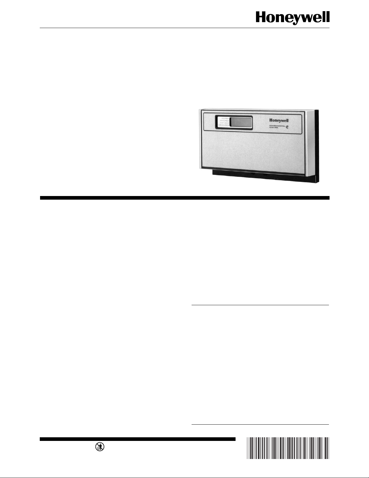
The T7200, T7300 Thermostats and Q7300 Subbases control commerical single zone heating, ventilating and air conditioning (HVAC) equipment.
■ One model can be used for single-stage and multi-
stage applications.
■ 7-day programming—two occupied/unoccupied
periods per day.
■ Individual temperature setpoints for:
—Occupied heat and cool.
—Unoccupied heat and cool.
■ Proportional plus integral control—eliminates temp-
erature fluctuations and thermostat tampering.
■ Intelligent Recovery™—automatically optimizes
start time depending on building load.
■ Intelligent Fan™—energizes fan on call for heating
or cooling only. Fan can be configured to run cont-
inuously in occupied mode.
■ Automatic heat/cool changeover.
■ Universal Versaguard™ Thermostat Guard avail-
able for T7200 and T7300/Q7300.
■ Locking setpoints and schedules eliminate tamp-
ering (use keyboard security).
■ One thermostat can be used for heat pump or con-
ventional control.
■ Optional remote sensors.
■ Configurable to vary fan and reversing valve operation.
■ Use with Q7300 to interface with C7400/W7459
Economizer System for total integration of rooftop
control.
■ Convenient overrides allow temporary changes.
■ Battery backup saves program and maintains clock
time during power failure.
■ Auxiliary contacts available for use with economizer.
CONTENTS
Specifications ................................................ 2
Ordering Information.................................... 2
Recycling Notice............................................ 4
Installation .................................................... 4
Temperature Averaging Networks
(See Fig. 5-9) ........................................ 5
Set Q7300 Subbase DIP Switches............. 6
Set Thermostat DIP Switches.................... 9
Set Thermostat Mini-Jumper .................. 11
Program the Thermostat ............................. 12
Checkout...................................................... 13
Test Mode................................................ 13
Operation .................................................... 15
Cross Reference .......................................... 18
Wiring Diagrams......................................... 22
Troubleshooting .......................................... 45
J. A. • Rev. 12-95 • • ©Honeywell Inc. 1995
M3375
1 63-4038—7
Page 2
T7200/T7300/Q7300
SPECIFICATIONS • ORDERING INFORMATION
Specifications
IMPORTANT: The specifications given in this publication
do not include normal manufacturing tolerances.
Therefore, this unit may not exactly match the listed
specifications. This product is tested and calibrated
under closely controlled conditions, and some minor
differences in performance can be expected if those
conditions are changed.
• T7300A is a fully configurable programmable commercial thermostat to be used with a Q7300 Subbase.
• T7300B is a fully configurable programmable commercial thermostat with the 3-HOUR OVERRIDE key in the
cover, to be used with a Q7300 Subbase. (See Fig. 2).
• T7300C is a fully configurable programmable commercial thermostat with limited access cover for easy programming. Cover includes Set Heat, Set Cool, Warmer,
T7200 AND T7300 THERMOSTATS
• T7200A is an autochangeover programmable commer-
Cooler and Occupied/Unoccupied keys. Use with Q7300
Subbase. (See Fig. 3).
cial thermostat to be used with a single stage conventional
heat/cool system.
•T7200B is an autochangeov er programmable commercial
Q7300 SUBBASE
Q7300 Subbases provide features listed in Table 1.
thermostat to be used w ith a sing le stage heat pump system .
TABLE 1—Q7300 SUBBASE FEATURES.
Model System Switch
Q7300A
Q7300B Heat-Off-Cool-Auto Auto-On 2 heat-1 cool; 2 heat-2 cool
Q7300C Em. Ht.-Heat-Off-
Q7300D None 1 stage heat pump compressor with
Q7300E None Conventional 1 heat-1 cool; 2 heat-2 cool
Q7300F None Aux. Ht. 1 stage heat pump compressor with
Q7300G Heat-Off-Cool-Auto None Conventional 1 stage heat with
Q7300L None Auto-On Heat Cool 2 stage heat (ML984 actuator/
a
a,b
None None None Conventional 1 heat-1 cool; 1 heat-2 cool
Cool-Auto
Select models do not have auxiliary relay output. The auxiliary relay output is used with an ecomonomizer for minimum
Fan
Switch LEDs Application Selectable Output
Em. Ht.,
Aux. Ht.
1 stage heat pump compressor with
auxiliary heat
2 stage heat pump compressor with
auxiliary heat
auxiliary heat
2 stage heat pump compressor with
auxiliary heat
auxiliary heat
2 stage heat pump compressor with
auxiliary heat
3-stage cool
V5013 Valve) 1 stage cool
c
1 heat-1 cool; 2 heat-1 cool
1 heat-1 cool; 2 heat-1 cool;
3 heat-1 cool
1 heat-1 cool; 2 heat-1 cool
1 heat-1 cool; 2 heat-1 cool;
3 heat-1 cool
1 heat-1 cool; 2 heat-1 cool
1 heat-1 cool; 2 heat-1 cool;
3 heat-1 cool
1 heat-3 cool (fixed)
1 heat-1 cool; 2 heat-1 cool
position control based on programmed time schedule. Can also be used for switching other external equipment.
b
Q7300A1000 model configures for 1 heat-1 cool only (fixed).
c
Uses conventional terminal designations. Compressor changeover is controlled by the heat pump equipment.
Ordering Information
When purchasing replacement and modernization products from your TRADELINE® wholesaler or distributor, refer to the Tradeline
Catalog or price sheets for complete ordering number, or specify—
1. Order number. 3. Order additional system components and system accessories
2. Accessories, if desired. separately.
If you have additional questions, need further information, or would like to comment on our products or services, please write or phone:
1. Your local Home and Building Control Sales Office (please check the white pages of your phone directory).
2. Home and Building Control Customer Relations
Honeywell, 1885 Douglas Drive North
Minneapolis, Minnesota 55422-4386
In Canada—Honeywell Limited/Honeywell Limitée, 35 Dynamic Drive, Scarborough, Ontario M1V 4Z9. International Sales and
Service Offices in all principal cities of the world. Manufacturing in Australia, Canada, Finland, France, Germany, Japan, Mexico,
Netherlands, Spain, Taiwan, United Kingdom, U.S.A.
63-4038—7 2
Page 3
THERMOSTAT
ELECTRICAL RATING: 24 to 30 Vac, 50/60 Hz.
SYSTEM CURRENT DRAW: 6 VA maximum at 30 Vac,
50 or 60 Hz.
OUTPUT RELAY DRAW: See Table 2.
TABLE 2—MAXIMUM AMPS AT 30 VAC.
Relay Running (A) Inrush (A)
Fan 1.6 3.5
Heat 1.6 3.5
Cool 1.6 7.5
Auxillary (Economizer) 1.6 3.5
TEMPERATURE:
Ratings:
Ambient: 40°F to 110°F (4°C to 43°C).
Shipping: -30°F to +150°F (-34°C to +65°C).
Display Accuracy: ±1°F (±1°C).
Setpoint:
Range: 45°F to 95°F (7°C to 35°C).
Differential: 2°F (1°C).
Default Settings: See Table 3.
TABLE 3—DEFAULT SETPOINTS.
Control Occupied Unoccupied
Heating 68°F (20°C) 55°F (13°C)
Cooling 78°F (26°C) 90°F (32°C)
T7200/T7300/Q7300
SPECIFICATIONS
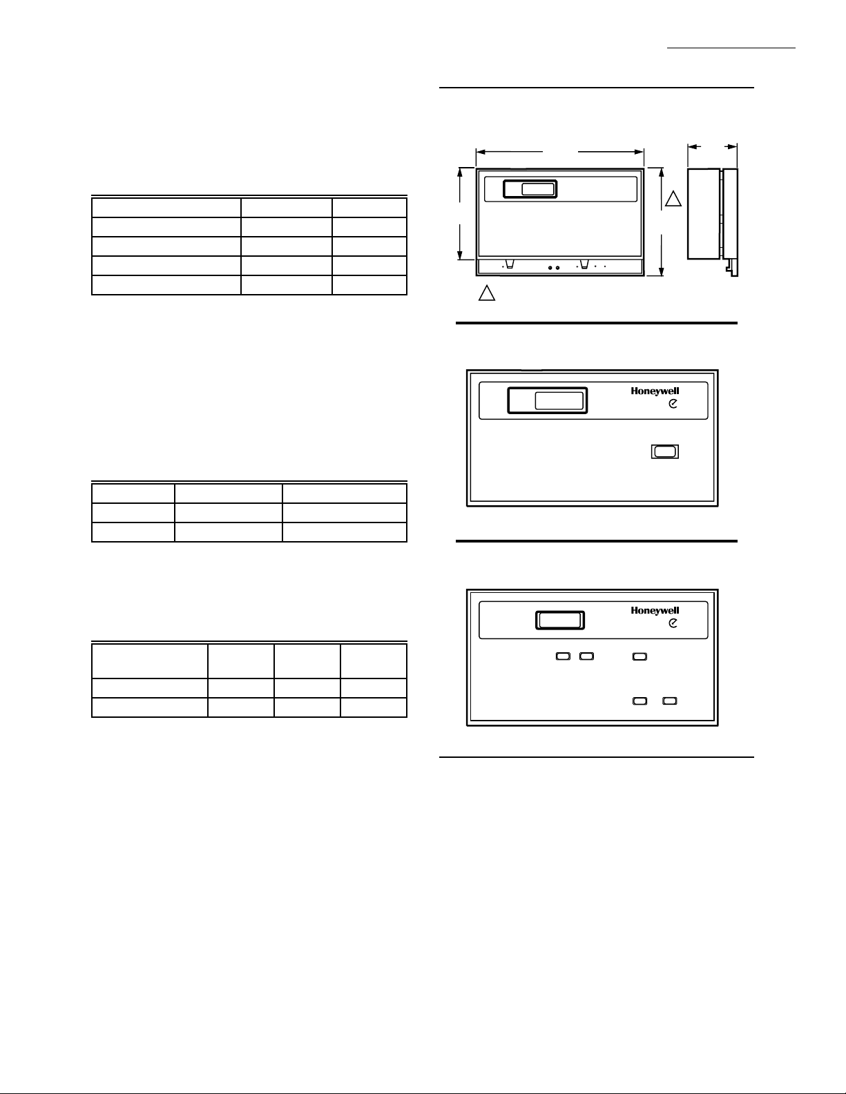
Fig. 1—Thermostat and subbase dimensions in
in. (mm).
8 (204)
4
(102)
FAN
1
EM. HEAT AUX. HEAT
ONAUTO COOLOFFHEATEM. HEAT
T7300/Q7300 ONLY.
Fig. 2—T7300B door.
OCCUPIED •
UNOCCUPIED •
CONT UNOC •
3 HR OCCUPIED •
ENVIRONMENTAL
CONTROL
4-5/8
(118)
3 HOUR
OCCUPIED
1-3/4
1
(41)
M4404
M4421
REMOTE SENSOR WIRING TEMPERATURE OFFSET:
Temperature offset occurs with 500 ft (157m) to 1000 ft
(305m) of 2-wire cable. See Table 4.
TABLE 4—TEMPERATURE OFFSET.
Temperature
Range 18 AWG 20 AWG 22 AWG
50-90°F -0.4°F -0.7°F -1.0°F
10-32°C -0.3°C -0.4°C -0.6°C
MINIMUM STAGE OPERATION TIME:
Conventional Heat: Two minutes On or Off.
Compressor: Two minutes On and four minutes Off.
HUMIDITY RATINGS: 5% to 90% RH, noncondensing.
CLOCK ACCURACY: ±1 minute per month.
BATTERY BACKUP: Up to 60 hours with fresh 9-volt
alkaline battery. Mallory MN11604™ or equivalent.
FINISH: Beige thermostats with brown subbases or Premier
White™ thermostats with light gray subbases.
DIMENSIONS: See Fig. 1.
T7300 Doors: See Fig. 2.
MOUNTING MEANS: T7200 Thermostat mounts on a
wallplate. The T7300 mounts on the Q7300 Subbase. The
Q7300 and wallplate mount horizontally on a wall or
outlet box with two no. 6 x 32 screws (included).
Fig. 3—T7300C door.
OCCUPIED •
UNOCCUPIED •
TO ADJUST HEAT
PRESS SET HEAT THEN
PRESS WARMER OR COOLER
TO ADJUST COOLING
PRESS SET COOL THEN
PRESS WARMER OR COOLER
FOR AFTER HOURS
PRESS OCCUPIED UNOCCUPIED
FOR BUSINESS HOURS
PRESS OCCUPIED UNOCCUPIED AGAIN
SET SET
HEAT COOL
TO ACCESS FULLY PROGRAMMABLE TIME AND TEMPERATURE FEATURES LIFT COVER
ENVIRONMENTAL
CONTROL
WARMER
COOLER
OCCUPIED
UNOCCUPIED
M4422
ACCESSORIES:
— 229997BU T7300B Conversion Kit. (See Fig. 2).
— 229997BY T7300A Conversion Kit. (See cover photo).
— 229997CE T7300C Conversion Kit. (See Fig. 3).
— 231054AA White Door Assembly for T7300C. (See
Fig. 3.
— 231055AA White Door Assembly for T7300B. (See
Fig. 2).
— 231056AA White Door Assembly for T7300A. (See
cover photo).
— 4074EEP Hardware for door and hinge pin assembly.
3 63-4038—7
Page 4
T7200/T7300/Q7300
SPECIFICATIONS • RECYCLING • INSTALLATION
— 4074EFS Bag Assembly (two sheet metal screws and
two machine screws).
— 4074EKA Bag Assembly (Allen wrench and four
Allen head screws).
— 4074ENE Hinge Pin Assembly.
— C7400 Enthalpy Sensor.
—M7415 Damper Actuator.
— T675A Temperature Control.
— T7022A1010 Remote Temperature Sensor.
— T7047C1025 Remote Temperature Sensor.
— T7047G1000 Remote Temperature Sensor.
If this control is replacing a control that contains mer-
cury in a sealed tube, do not place your old control in the
trash.
Contact your local waste management authority for
instructions regarding recycling and the proper disposal of
— T7147A1002 Remote Temperature Sensor and Over-
ride Module.
— T7147A1010 Remote Temperature Sensor and Over-
ride Module.
— T7147A1028 Remote Temperature Sensor and Over-
ride Module.
— R8222 Switching Relay.
—W950A System Supervisor.
—W859D Packaged Economizer.
—W7459 Economizer Logic Module.
Recycling Notice
M3375
this control, or of an old control containing mercury in a
sealed tube.
Installation
WHEN INSTALLING THIS PRODUCT…
1. Read these instructions carefully. Failure to follow
them could damage the product or cause a hazardous condition.
2. Check the ratings given on the product to make sure
the product is suitable for your application.
3. Installer must be a trained, experienced service technician.
4. Allow thermostat to warm to room temperature before
operating.
5. After installation is complete, check out product operation as provided in these instructions.
CA UTION
Disconnect power supply before beginning installation to prevent electrical shock or equipment
damage.
LOCATION
Thermostat Without Remote-Mounted
Temperature Sensor
Install the thermostat about 5 ft (1.5m) above the floor in
an area with good air circulation at average temperature.
See Fig. 4.
Do not mount the thermostat where it can be affected by:
— drafts or dead spots behind doors, in corners or under
cabinets.
— hot or cold air from ducts.
— radiant heat from the sun, fireplace, or appliances.
— concealed pipes and chimneys.
— unheated (uncooled) areas such as an outside wall
behind the thermostat.
Thermostat With Remote-Mounted
Temperature Sensor(s)
Install the thermostat in an area that is accessible for
setting and adjusting the temperature and settings.
Install the remote-mounted sensor(s) about 5 ft (1.5m)
above the floor in an area with good air circulation at
average temperature. See Fig. 4.
Do not mount the sensor(s) where it can be affected by:
— drafts or dead spots behind doors, in corners or under
cabinets.
— hot or cold air from ducts.
— radiant heat from the sun, fireplace, or appliances.
— concealed pipes and chimneys.
— unheated (uncooled) areas such as an outside wall
behind the thermostat.
If more than one remote sensor is required, they must be
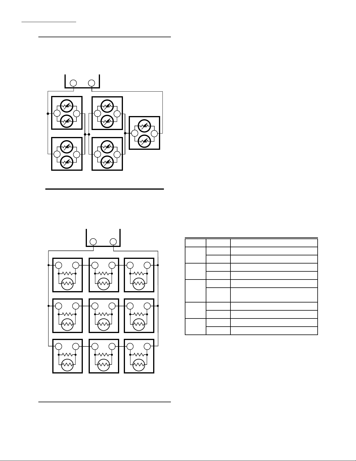
arranged in a temperature averaging network consisting of
two, three, four, five, or nine sensors. Instal as shown in
Fig. 5-9.
REPLACE AN EXISTING THERMOSTAT OR
NEW INSTALLATION
Replace An Existing Thermostat
Turn off all sources of power for the thermostat. Re-
move any existing wallplate or subbase from the wall. To
avoid miswiring later, label or write down each wire color
with the letter or number on the wiring terminal as the wire
is removed.
63-4038—7 4
Page 5
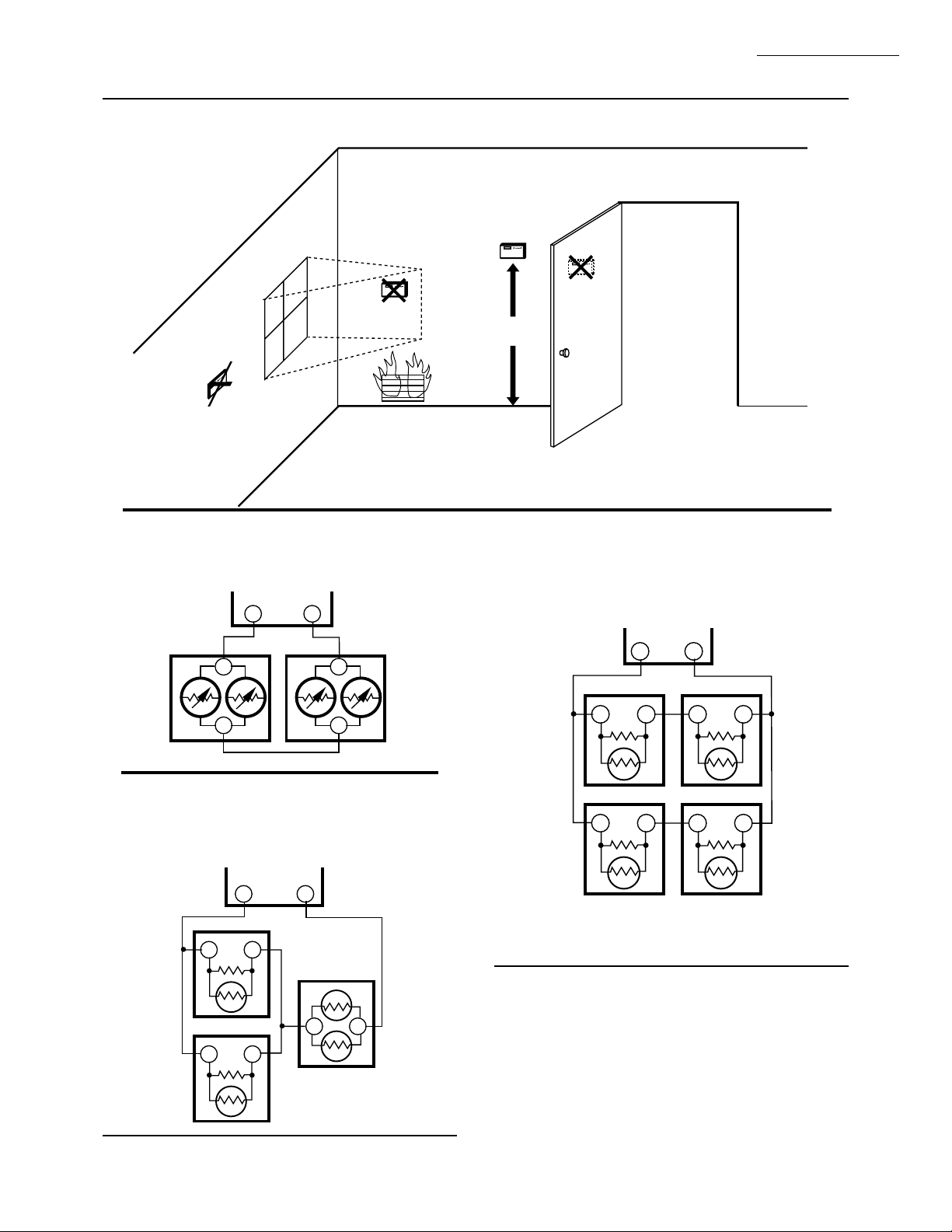
Fig. 4—Location for installing thermostat or remote-mounted sensor.
YES
NO
5 FEET
[1.5 METERS]
NO
T7200/T7300/Q7300
INSTALLATION
NO
M4385
Fig. 5—Two T7047G1000 Sensors providing a
temperature averaging network for a T7300/
Q7300 Thermostat/Subbase.
Q7300
TT
T7047G1000T7047G1000
T
T
T
T
M3421
Fig. 6—Two T7047C1025 and one T7047G1000
Sensors providing a temperature averaging
network for a T7300/Q7300 Thermostat/Subbase.
Q7300
TT
T7047C
TT
T7047G1000
Fig. 7—Four T7047C1025 Sensors providing a
temperature averaging network for a T7300/
Q7300 Thermostat /Subbase.
Q7300
TT
T7047C
TT
T7047C
TT
T7047C
TT
T7047C
TT
M3420
T7047C
TT
TT
M3418
5 63-4038—7
Page 6
T7200/T7300/Q7300
INSTALLATION
Fig. 8—Five T7047G1000 Sensors providing a
temperature averaging network for a T7300/
Q7300 Thermostat/Subbase.
Q7300
TT
T7047G
T
T7047G
T
T7047G
T
T
T
T7047G
T
T
T7047G
T
T
M3422
Fig. 9—Nine T7047C1025 Sensors providing a
temperature averaging network for a T7300/
Q7300 Thermostat/Subbase.
New Installation
Run cable to a hole at the selected wall location for the
thermostat and pull about 3 in. (76 mm) of wire through the
opening. Color-coded, 18-gauge thermostat cable with at
least one conductor for each wiring terminal is recommended. Good service practice recommends selecting a
cable with one or two extra conductors than the immediate
application requires.
If using remote temperature sensor(s) or LAN override
switch module, refer to the mounting instructions included
with the device for wiring cable requirements. Route cable
away from sources of electrical noise.
IMPORTANT: The remote sensor(s) or override switch
T
wires must be in a shielded cable if bundled or placed
in the same conduit with the cooling control wires.
Earth ground the shield at the thermostat.
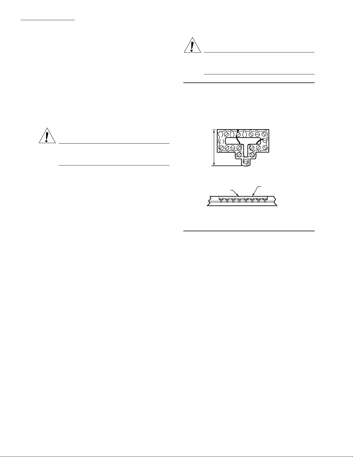
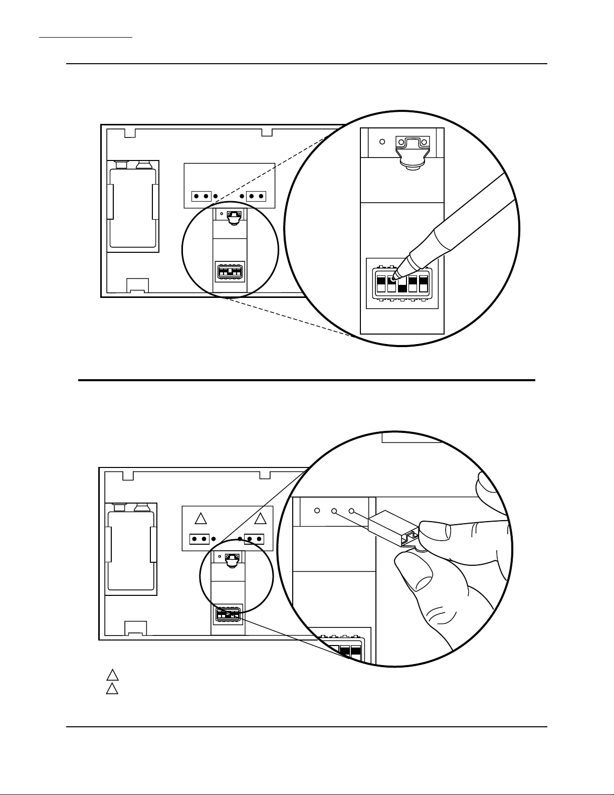
SET Q7300 SUBBASE DIP SWITCHES
NOTE: Subbase dip switches are not available on the T7200
Wallplate.
The Q7300 Subbase provides the T7300 Thermostat
with an interface to the single zone HVAC system. See
Table 5 for DIP switch settings. The subbase DIP switches
are located on the front and to the right of the wiring
terminals. See Fig. 10. Set the DIP switches for the system
being controlled.
T7047C
TT
T7047C
TT
T7047C
TT
Q7300
TT
T7047C
TT
T7047C
TT
T7047C
TT
T7047C
TT
T7047C
TT
T7047C
TT
M3419
TABLE 5—SUBBASE DIP SWITCH SETTINGS.
Switch Setting Function
a
1
OFF 1 stage heat
ONb2 stage heat
a
2
OFF 1 stage cool
ONb2 stage cool
3 OFF Proportional control (allows droop)
ONbProportional plus integral (P+I)
control (droopless)
c
4
ONbEnergizes fan on cool only
OFF Energizes fan on heat and cool
5ONbUse internal sensor
OFF Use remote sensor
a
No effect on 1 heat/1 cool (Q7300A) or 1 heat/3 cool
(Q7300G) models.
b
Factory setting.
c
No effect on heat pump systems.
MOUNT SUBBASE OR WALLPLATE
The subbase or wallplate can be mounted on a horizon-
tal outlet box or directly on the wall. For an outlet box
installation, go to step 3.
63-4038—7 6
Page 7
T7200/T7300/Q7300
INSTALLATION
1. For a wall installation, hold subbase or wallplate in
position and mark holes for the anchors. See Fig. 4. Wall
anchors must be obtained locally. Be careful that the wires do
not fall back into the wall opening. Set aside subbase or
wallplate.
Fig. 10—Setting subbase DIP switches.
BA3A2W2Y2TA1 T
Y1
GRCRH
LED1
1
CONFIGURATION OF ILLUSTRATED SWITCH IS:
1 – ON
2 – OFF
3 – OFF
4 – ON
5 – ON
CA1
LED2 COM
CA2 CA3 CA4 CA5
2. Drill four 3/16 in. (4.8 mm) holes and gently tap
anchors into the holes until flush with the wall.
3. Pull wires through the cable opening. See Fig. 11.
1
O
N
1
234
5
M4401
Fig. 11—Installing subbase on outlet box or on wall.
BA3A2W2Y2TA1 T
Y1
GRCRH
SHEET METAL
SCREWS
MOUNTING TO WALL BOARD
CA2 CA3 CA4 CA5
CA1
LED2 COM
LED1
MACHINE
SCREWS
OR
BA3A2W2Y2TA1 T
Y1
GRCRH
MOUNTING TO HORIZONTAL 2 X 4 JUNCTION BOX
CA2 CA3 CA4 CA5
CA1
LED2 COM
LED1
M4410
7 63-4038—7
Page 8
T7200/T7300/Q7300
INSTALLATION
4. Secure the subbase or wallplate with the screws provided. Do not fully tighten the screws.
5. Level the subbase or wallplate for appearance only.
Leveling is not required for operation. Securely tighten the
screws.
WIRE SUBBASE OR WALLPLATE
CA UTION
Never install more than one wire per terminal
unless using factory-supplied jumper with spade
terminal.
IMPORTANT: Most equipment manufacturers size system
transformers for the equipment installed at the factory. Before connection, be sure that the system transformer can supply the T7200 OR T7300 and Q7300
with adequate power (6 VA). If less than 6 VA is
available, install a separate 24 Vac transformer.
CA UTION
Disconnect power supply before beginning installation to prevent electrical shock or equipment
damage.
All wiring must comply with local electrical codes and
ordinances.
IMPORTANT: Use 18 gauge, solid-conductor wire when-
ever possible. If using 18 gauge stranded wire, no
more than 10 wires can be used. Do not use larger
than 18 gauge wire.
Follow equipment manufacturer’s wiring instructions
when available. See Fig. 23-46 for wiring diagrams. To
wire subbase, proceed as follows:
1. Connect the correct wires to the terminals as shown in
applicable diagram; the terminal barrier allows straight or
wraparound wiring connection. See Fig. 12. A letter code is
located near each terminal for identification. Typical terminal designation and wiring connections are listed in Table
6. Connect remote temperature sensor or override switch
module.
NOTE: If a remote sensor is used, be sure that the Q7300 DIP
switch 5 is placed in the OFF position.
Fig. 12—Barrier configuration. Keep wiring
restricted to recessed area surrounding terminals.
FOR STRAIGHT
INSERTION –
STRIP 5/16 in. [8 mm]
FOR WRAPAROUND –
RESTRICT
WIRING TO
THIS AREA
FRONT VIEW OF
TERMINAL AREA
WIRING TO BE BELOW
THIS SURFACE
CROSS-SECTIONAL VIEW OF
TERMINAL AREA
STRIP 7/16 in. [11 mm]
TOP SURFACE
OF SUBBASE
M3062
2. Firmly tighten each terminal screw. Loose or intermittent wire connections can cause inconsistent system operation.
3. Fit wires as close as possible to the subbase. Push
excess wire back into the hole.
4. Plug hole with nonflammable insulation to prevent
drafts from affecting the thermostat.
Refer to Fig. 23-46 for typical hookups. When system
installation is complete, perform the initial power up procedure in the Checkout section.
63-4038—7 8
Page 9
T7200/T7300/Q7300
TABLE 6—TERMINAL DESIGNATIONS.
Standard
Terminal
Designation
BHeating damper motor; changeover valve/relay Output 24 Vac powered contact
EKEmergency heat relay Output 24 Vac powered contact
GFFan relay coil Output 24 Vac powered contact
ORCooling damper motor; changeover valve/relay Output 24 Vac powered contact
RVPower connection to transformer (internally
RC Power connection to cooling transformer Input
RH Power connection to heating transformer Input
W1 H1, R3 Stage 1 heating control Output 24 Vac powered contact
W2 H2, Y, R4 Stage 2 heating control Output 24 Vac powered contact
W3 Stage 3 heating control Output 24 Vac powered contact
Y1 C1, M Stage 1 cooling control Output 24 Vac powered contact
Y2 C2 Stage 2 cooling control Output 24 Vac powered contact
a
Y3
XX1,X2,C Common connection Input
T
LED1,
LED2, COM
YMCompressor contactor
A1, A2, A3 Auxiliary relay Output Dry contact
CA1-CA5
a
Q7300G only.
b
Shielded cable can be required in some installations where electrical interference (noise) can cause control problems.
Alternate
Designations Or
Customer Specials Typical Connection Function Terminal Type
Input
connected for heating and cooling)
Stage 3 cooling control
Remote sensor
L, C, H HSII control panel
OMomentary circuit, changeover
A,A1,A2,Z,C,L LEDs Annunciation
TExternal temperature readout, T relay
R1, R2 LO and HI speed fan relays
RS Cooling contactor
Remote override
b
a
b
Output 24 Vac powered contact
Input
Input Low power
INSTALLATION
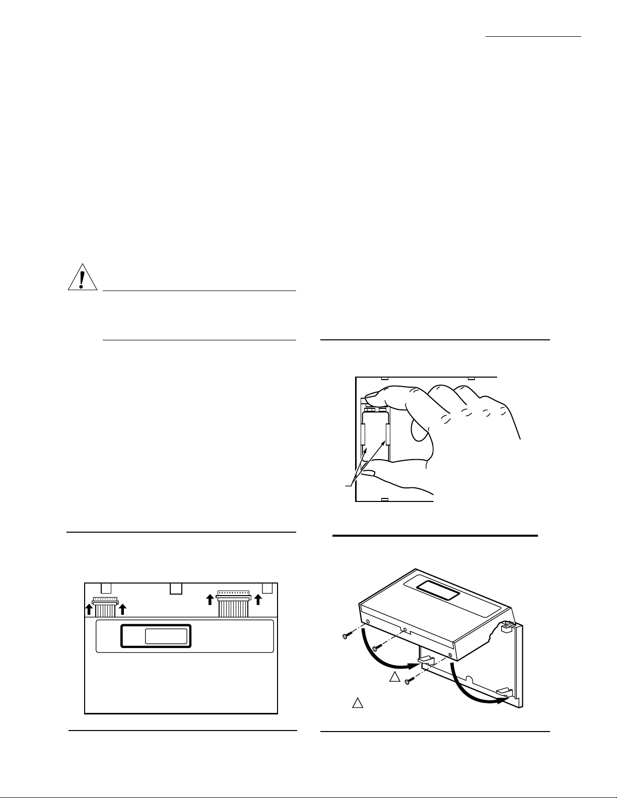
SET THERMOSTAT DIP SWITCHES
The thermostat DIP switches provide the thermostat
with an interface to the single zone HVAC system. See
Table 7 for DIP switch settings. The thermostat DIP switches
are located on the back of the thermostat. See Fig. 13. Set
the DIP switches for the desired thermostat features and the
system being controlled.
IMPORTANT: The thermostat configuration must match
the application, or the control logic will not function
properly.
TABLE 7—THERMOSTAT DIP SWITCH SETTINGS
Switch Setting Function
1ONa°F display
OFF °C display
2ONa12 hour clock display
OFF 24 hour clock display
3ON
a,b
Intermittent fan operation in occupied
period
OFF Continuous fan operation in occupied
period
4 Nonfunctional switch
5ONaKeyboard is used for programming
OFF Keyboard disabled, but can be used to
review program, perform overrides
and make clock changes.
a
Factory setting.
b
Q7300B,C,D,E,L: fan switch will override this switch
setting.
Q7300A,F,G: no override is available.
9 63-4038—7
Page 10
T7200/T7300/Q7300
INSTALLATION
Fig. 13—Setting thermostat DIP switches.
T7300 ONLY
HEAT PUMP CONV
12 HR. TIME
°F - TEMP
ON
1
°C
12 HR. TIME
INT - FAN
90
45
234
24
CON
ON - KEYBD
5
OFF
°F - TEMP
ON
45
1
234
24
°C
M4085A
Fig. 14—Setting thermostat mini-jumper for conventional or heat pump system.
T7300 ONLY
1 2
HEAT PUMP CONV
- KEYBD
INT - FAN
5
OFF
CON
ON - KEYBD
12 HR. TIME
INT - FAN
°F - TEMP
ON
90
45
1
234
5
24
°C
OFF
CON
ONLY PUT MINI-JUMPER IN THIS POSITION WHEN USING Q7300C,D, OR F SUBBASES.
1
2
ONLY PUT MINI-JUMPER IN THIS POSITION WHEN USING Q7300A,B,E, OR G SUBBASES.
63-4038—7 10
12 HR. TIME
INT - FAN
°F - TEMP
90
ON - KEYBD
M4086A
Page 11
BATTERY
SNAPS
STEP 1:
STEP 2:
STEP 3:
CONNECT THERMOSTAT
CABLES TO THE SUBBASE.
FIRST CONNECT THE 12 PIN
THEN THE 9 PIN.
SNAP BATTERY INTO PLACE.
SLIDE BATTERY UP TO THE
BATTERY CONNECTOR
UNTIL CONNECTED.
M4408
T7200/T7300/Q7300
INSTALLATION
SET THERMOSTAT MINI-JUMPER
NOTE: This operation must be done prior to installing the
batteries. If batteries are installed prior to this operation,
remove battery for 15 minutes and begin.
The T7300 is factory-set for conventional system control using the Q7300A,B,E,G. If using with a heat pump
and Q7300C,D,F, locate the mini-jumper on the back of the
T7300. See Fig. 14. Pull the mini-jumper off the two
CONV pins and move to the two HEAT PUMP pins. This
changes the thermostat to the heat pump algorithm.
If you wish to change the control of the thermostat
because a new subbase has been purchased, remove battery
for 15 minutes, change mini-jumper position, and re-install
battery.
MOUNT THERMOSTAT
CA UTION
Always disconnect power supply and remove battery from the T7300 before connecting the ribbon
cables to prevent electrical shock and equipment
damage.
Use the following procedure to connect the T7300 ribbon cables to the Q7300.
1. Check that the 24 Vac power supply is disconnected
from the Q7300.
2. Check that the 9 Vdc battery is not installed in the
T7300.
INSTALL BATTERY (OPTIONAL)
The 9 volt battery is not necessary for the operation of
the thermostat, but holds the program during power outages. When the power is restored, the system will resume
normal operation. Without the battery, the system will
follow the default setpoints. See Table 3. Use the following
steps to install a battery:
1. Locate the battery holder on the back of the thermo-
stat.
2. Slide the battery up to the connector until it is firmly
seated. See Fig. 16.
NOTE: Observe the polarity when snapping a 9 volt alkaline
battery into the holder.
NOTE: The plugs must be firmly seated on the connectors
for the thermostat to work properly.
6. Hang the top edge of the thermostat on the subbase
hooks. See Fig. 17.
7. Swing down and press on the lower edge until the
thermostat snaps in place.
8. Insert and tighten three Allen head screws on the
bottom of the thermostat. See Fig. 17.
Fig. 16—Installing optional 9 volt battery.
IMPORTANT: First be sure to connect the 12 pin ribbon
cable to the Q7300.
3. Connect the 12 pin (larger) ribbon cable to the Q7300.
See Fig. 15.
4. Connect the 9 pin (smaller) ribbon cable to the Q7300.
5. If using a 9 Vdc battery, go to the Install Battery
Backup section for installation instructions.
Fig. 15—Connecting the pin ribbon cables to the
subbase connectors.
9-PIN SUBBASE
CONNECTOR
12-PIN SUBBASE
CONNECTOR
M4403
Fig. 17—Mounting thermostat on subbase.
1
1
DO NOT OVERTIGHTEN SCREWS
M4391
11 63-4038—7
Page 12
T7200/T7300/Q7300
PROGRAM THE THERMOSTAT
Program the Thermostat
OVERVIEW
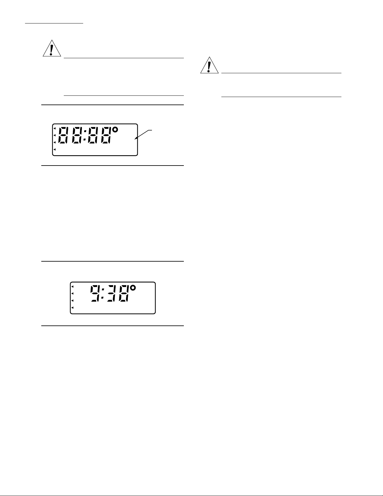
The keyboard is located behind the thermostat flip-up
cover. See Fig. 18. There are 16 keys to set, review and
modify programmed times and temperatures. The liquid
crystal display (LCD) shows day, time or temperature and
which programming period is operating.
The thermostat can be set for two occupied and two
unoccupied time and temperatures for each day of the week
(28 independent settings). The two override keys provide
quick temporary programming changes for increased occupant comfort.
IMPORTANT: To program the thermostat, 24 Vac is re-
quired (turn on system power) and the keyboard lockout switch (see Fig. 27) must be in the ON-KEYBD
position.
Fig. 18—Thermostat programming keys and
LCD display.
OCCUPIED •
UNOCCUPIED •
3 HR OCCUPIED •
SET SET START TIME
CLOCK
DAY
CONT UNOC •
SELECT
DAY
COPY
11:32
OCCUPIED
START TIME
START TIME
HEAT
AM
SET TEMPERATURE DATA CHANGE
OCCUPIED
OCCUPIED
COOL
HEAT
UNOC
UNOC
UNOC
HEAT
COOL
DISPLAY
CLEAR
START TIME
OVERRIDE
3 HOUR
+
OCCUPIED
CONT
–
UNOC
NOTE: The programming times are in intervals of ten
minutes; i.e., 8:00, 8:10, 8:20.
1. Press the SELECT DAY key. The display shows the
abbreviation for a day.
2. Press and hold the + or - key until the desired day
appears.
3. Press the OCCUPIED START TIME key. The pro-
gram indicator will point to OCCUPIED.
4. Press and hold the + or - key until the desired start time
appears.
NOTE: Anytime a start time is not required, press the
CLEAR START TIME key.
5. Press the UNOC START TIME key. The program
indicator will point to UNOCCUPIED.
6. Press and hold the + or - key until the desired start time
appears.
7. To program a second occupied start time for the
selected day, repeat Step 3 until four dashes (----) are displayed or the second start time (if previously programmed) is
displayed. Then repeat Step 4.
8. To program a second unoccupied start time for the
selected day, repeat Step 5 until four dashes (----) are displayed or the second start time (if previously programmed) is
displayed. Then repeat Step 6.
9. Repeat Steps 1 through 8 for each remaining day of the
week or refer to the following section, COPY A DAY.
M4384
SET CURRENT TIME/DAY
1. Set the current time by pressing and releasing the
CLOCK key once.
2. Press the + or - key until the current time appears on the
LCD.
3. Set the current day by pressing and releasing the DAY
key once.
4. Press the + or - key until the current day appears on the
LCD.
NOTE: Su=Sunday; Mo=Monday; Tu=Tuesday; We=
Wednesday; Th=Thursday; Fr=Friday; Sa=Saturday.
SET PROGRAM TIMES
IMPORTANT: The thermostat will remain in occupied
mode from the point of initial programming until it
encounters the first unoccupied start time. To avoid
the unnecessary occupied period following initial programming, set a 12:00 AM unoccupied start time on
the thermostat when programmed.
COPY A DAY
1. Press the SELECT DAY key. The display shows the
abbreviation for a day.
2. Press and hold the + or - key until the day to be copied
from appears.
3. Press the COPY key.
4. Press and hold the + or - key until the day to be copied
to appears.
NOTE: The day to be copied from will remain on the display.
5. Press the COPY key a second time to perform the
copy.
6. Repeat Steps 3 to 5 to copy to another day.
SET PROGRAM TEMPERATURE SETPOINTS
NOTE: The setpoint temperature range is 45°F (unoccupied
heat) to 95°F (unoccupied cool). The occupied heat setpoint
must be at least 2°F less than the occupied cool setpoint.
1. Press the SET TEMPERATURE key (OCCUPIED
HEAT, OCCUPIED COOL, UNOC HEAT, or UNOC
COOL). The program indicator will point to OCCUPIED or
UNOCCUPIED and the LCD will indicate HEAT or COOL.
63-4038—7 12
Page 13

T7200/T7300/Q7300
PROGRAM THE THERMOSTAT • CHECKOUT
2. Press and hold the + or - key until the desired tempera-
ture appears.
3. Repeat Steps 1 and 2 until all four temperatures are set.
SET OPERATING DISPLAY
The LCD can show time or temperature. To change the
current display, press the DISPLAY key until the desired
operating display appears.
CLEAR START TIME
1. Press the SELECT DAY key.
2. Press and hold the + or - key until the desired day
appears.
3. Press and hold the OCCUPIED START TIME or
the UNOC START TIME key until the time to clear
appears.
4. Press and hold the CLEAR START TIME key until
the display shows four dashes (----).
NOTE: If there is a second OCCUPIED setting, the start for
time this setting will appear instead of four dashes (----).
TEMPORARILY OVERRIDE PROGRAM
There are three overrides available. The 3 hour occupied
overrides can be initiated from a remote location or the
thermostat. The 3 hour occupied override without + or -
keys can also be initiated from the T7300B cover.
NOTE: Pressing the DISPLAY key at anytime will return
the thermostat to the program.
3 Hour Occupied
The 3 HOUR OCCUPIED key is used to override the
unoccupied program when people need to use the area
temporarily (working late, weekends or holidays).
1. Press the 3 HOUR OCCUPIED key to change the
unoccupied temperature setting to the occupied setpoint for
three hours.
NOTE: The program indicator will point to 3 HR OCCU-
PIED while the override is in effect.
3 Hour Occupied with + or - Key
SET + OR - KEY VALUE
When using the + or - key with the 3 HOUR OCCU-
PIED key, the + or - key has a preassigned value of 0 to 5°F
(default is 0). Use the following steps to check or change
the value:
1. Press the 3 HOUR OCCUPIED key. The program
indicator will point to 3 HR OCCUPIED.
2. Press the DISPLAY key. The LCD will show a
number from 0 to 5.
3. Press the + or - key to change the value.
4. Press the DISPLAY key to return to the program.
Set 3 Hour Occupied Override With + or - Key
The 3 HOUR OCCUPIED key with the + or - key will
override the unoccupied program for three hours with the
occupied temperature setpoint + the preassigned key value
(see Set + or - Key Value section).
1. Press the 3 HOUR OCCUPIED key to change the
unoccupied temperature setting to the occupied setpoint for
three hours.
2. Press the + key to increase or press the - key to
decrease the occupied setpoint by the key value.
EXAMPLE: Unoccupied setpoint is 62°F, occupied
setpoint is 70°F and key value is 3°F. Pressing the
3 HOUR OCCUPIED key and the + key will change
the setpoint from 62°F to 70°F plus 3°F or 73°F.
Pressing the - key would change the setpoint to 70°F
minus 3°F or 67°F.
NOTE: The program indicator will point to 3 HR OCCU-
PIED while the override is in effect. The LCD will not
reflect the key value.
Cont Unoc
The continuous unoccupied override feature holds the
setpoint at the unoccupied temperature setpoint until the
DISPLAY or CONT UNOC key is pressed. This override
is used when the area will be closed for a temporary closing
such as a long holiday.
1. Press the CONT UNOC key to hold the temperature
at the unoccupied setpoint.
2. Press the CONT UNOC key again to return to the
program.
OVERVIEW
Check that all wiring is correctly completed and all
sensors are installed. The thermostat should be mounted on
the wallplate or subbase. If the thermostat has not been
programmed, when the power is first turned on, the LCD
will show four dashes (----). Without programming, the
thermostat will operate from default temperature setpoints
(see OPERATION section).
NOTE: It is helpful to program the thermostat before using
the Checkout procedure. Refer to the Programming sec-
tion to set a program.
Checkout
If the display has two dashes and a degree sign (--°), wait
sixty seconds and press the DISPLAY key twice. If the
display does not change or is blank, refer to the Troubleshooting section.
TEST MODE
The thermostat has a test mode that aids the installer in
performing the checkout. The test mode overrides the
minimum on and off times so the checkout can be quickly
performed. Press the CLOCK and DAY keys at the same
time to start the test mode. All the display segments will
appear. See Fig. 19
13 63-4038—7
Page 14
T7200/T7300/Q7300
CHECKOUT
CA UTION
Do not use the test mode for longer than 10 minutes. The test mode overrides the minimum on and
off times that protect the system. Equipment damage can result if the thermostat remains in the test
mode.
COOL
Move switch to auto.
CA UTION
Do not operate cooling if outdoor temperature is
below 50°F (10°C). Refer to the manufacturer
recommendations.
Fig. 19—All segments on display.
TEST MODE
INDICATOR
M4415
S
U
M
O
TUWETHFRS
AM
PM
A
COMM
HEAT
● ● ●
COOL
BATT
To discontinue the test mode at any time, press the
CLOCK and DAY keys at the same time. The Test Mode
Indicators will no longer show on the screen.
HEAT
NOTE: When the thermostat is used with a subbase with
subbase and fan switches, set the switches to AUTO.
1. Press the CLOCK and DAY keys at the same time.
This starts the test mode.
2. Press the DISPLAY key. See Fig. 20.
Fig. 20—Display when starting test sequence.
COMM
HEAT
AM
● ● ●
COOL
S
U
BATT
M4418
NOTE: When cooling setting changes, thermostat will wait
up to five minutes before turning on the cooling equip-
ment. This delay is to protect the compressor.
1. Press the OCCUPIED COOL key.
2. Press the - key to lower the setpoint 5°F (3°C) below
the room temperature. The cooling should start (both stages
if multistage), and the fan should run.
NOTE: It can be necessary to change the OCCUPIED
HEAT setpoint. However, be aware that the OCCUPIED
HEAT and OCCUPIED COOL setpoints must have a
2°F difference.
3. Press the OCCUPIED COOL key.
4. Press the + key to raise the setpoint 5°F (3°C) above
the room temperature. The cooling and fan should shut off.
When the thermostat has a system switch, move the
switch to the COOL position and repeat Steps 1 through 4.
Move the system switch to the OFF position. All heating
or cooling should stop.
FAN
Thermostat
Fan Switch (located on the back of the thermostat):
— CON: Fan operates continuously in the occupied
mode.
— INT-FAN: Fan operates directly with the thermo-
stat call for heating or cooling in the occupied
mode.
Subbase
3. Press the OCCUPIED HEAT key.
4. Press the + key to raise the setpoint 5°F (3°C) above
the room temperature. The heating should start (both stages
if multistage), and the fan should run (may be a short delay on
forced air systems).
NOTE: It can be necessary to change the OCCUPIED
COOL setpoint. However, be aware that OCCUPIED
HEAT and OCCUPIED COOL setpoints must have a
2°F difference.
5. Press the OCCUPIED HEAT key.
6. Press the - key to lower the setpoint 5°F (3°C) below
the room temperature. The heating should shut off, followed
by the fan shutoff.
When the thermostat has a system switch, move the
switch to the HEAT position and repeat steps 3 through 6.
63-4038—7 14
NOTE: Subbase fan switch overrides the thermostat fan
switch.
Subbase Dip Switch No. 4:
— ON: Fan operates only with cool.
— OFF: Fan operates with heat and cool.
Q7300E Fan Switch:
— ON: Fan operates continuously.
— AUTO: Fan operates directly with the thermostat
call for heating or cooling.
IMPORTANT: Press the CLOCK and DAY keys at the same
time to discontinue the test mode. The Test Mode Indicators will no longer show on the screen. See Fig. 19.
Page 15
T7200/T7300/Q7300
OPERATION
Operation
T7200/T7300 RELAY LOGIC
The T7300 contains three switching relays. When the
mini-jumper is set for conventional applications, the relays
control first stage cooling, first stage heating, and fan.
When the mini-jumper is set for heat pump applications,
the relays control the heat pump compressor, auxiliary heat,
and fan. Because of this change in switching logic, it is
important to use Q7300C,D, or F subbases when the T7300
is set for heat pump applications and use Q7300A,B,E,G
subbases when the T7300 is set for conventional applications.
The T7200A Relay Logic is for conventional applications. The T7300B Relay Logic is for heat pump applications.
T7200/T7300 AND CONVENTIONAL
THERMOSTATS
P+I Control
The T7200/T7300 microprocessor based control requires
that the user understands temperature control and thermostat performance. A conventional electromechanical or electronic thermostat does not control temperature precisely at
setpoint. Typically, there is an offset (droop) in the control
point as the system load changes. This is a phenomenon
that most people in the industry know and accept. Many
factors contribute to offset including switch differential,
thermal lag, overshoot, cycle rates and system load.
The thermostat microprocessor simultaneously gathers,
compares and computes data. Using this data, it controls a
wide variety of functions. The special proprietary algorithm (program) in the thermostat eliminates the factors
causing offset. This makes temperature control more accurate than the conventional electromechanical or electronic
thermostats. The temperature control algorithm is called
proportional plus integral (P+I) control.
The thermostat sensor, located on the thermostat or
remote, senses the current space temperature. The proportional error is calculated by comparing the sensed temperature to the programmed setpoint. The deviation from the
setpoint is the proportional error.
The thermostat also determines integral error, which is a
deviation based on the length of error time. The sum of the
two errors is the (P+I) error. The cycle rate used to reach
and maintain the setpoint temperature is computed using
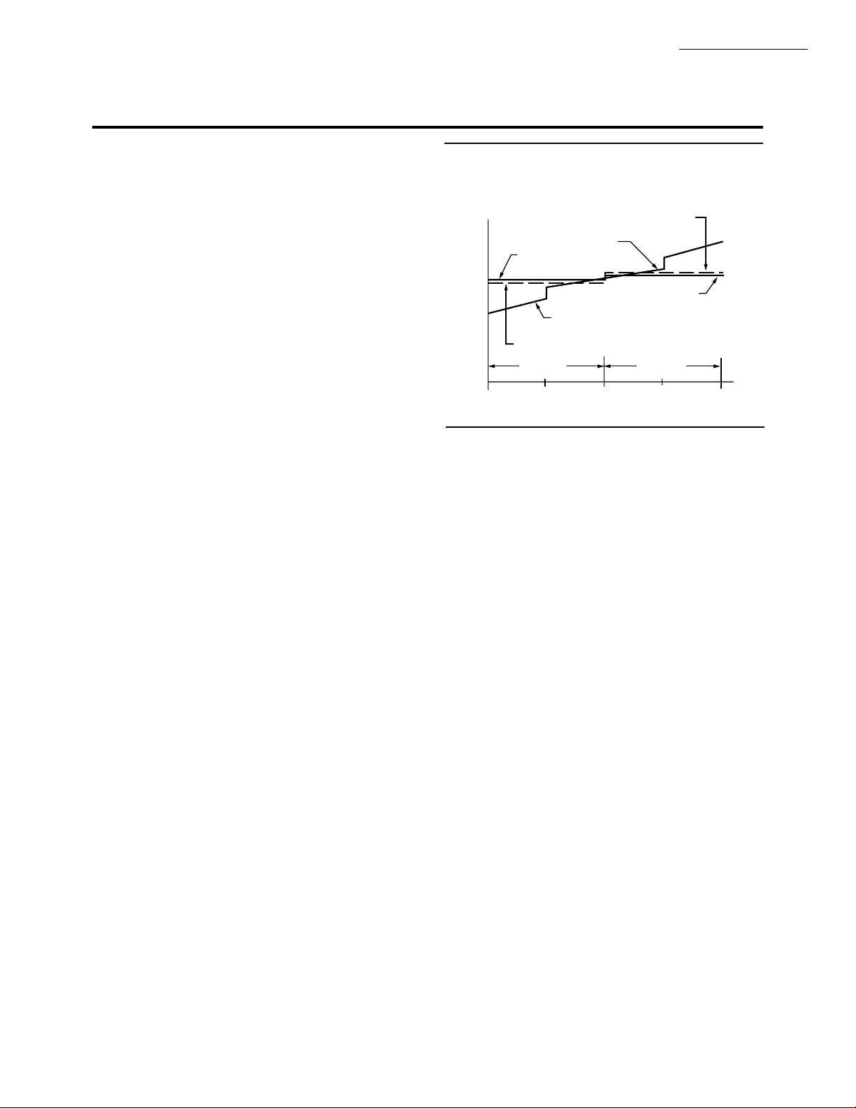
the P+I. The addition of the integral error is what differentiates the thermostat from many other electronic and electromechanical thermostats. See Fig. 21.
Fig. 21—Proportional temperature control
versus P+I temperature control.
THERMOSTAT
COOL SETPOINT
PROPORTIONAL COOL
CONTROL POINT
P+I CONTROL
POINT
P+I CONTROL POINT
TEMPERATURE
100 50 0 50 100
PROPORTIONAL HEAT
CONTROL POINT
THERMOSTAT
HEAT SETPOINT
HEATING
PERCENT LOAD
COOLING
M4414
While the thermostat is designed to eliminate droop,
allowing droop can be desirable in applications where
building visitors are dressed for the weather and their stays
are brief. Examples of these applications include fast food
restaurants and convenience stores. The droopless feature
of the thermostat can be overridden by placing the droop/
droopless select switch located on the subbase in the OFF
position. This removes the integral calculation from the
thermostat control scheme, allowing only the proportional
control to occur.
EQUIPMENT PROTECTION
As part of the operational sequence, the T7200/T7300
microprocessor also incorporates minimum On and Off
times for all heating and cooling stages. Minimum On and
Off times assure that rapid cycling of equipment will not
occur, extending equipment life. Minimum On/Off times
for compressor stages are two minutes On and four minutes
Off. Minimum On/Off times for heat (electric resistive or
gas) are two minutes.
T7200/T7300 THERMOSTAT OPERATION
Startup
When power to the thermostat is turned on, a startup and
initialization program begins. The startup takes place after
total loss of power (24 Vac and battery backup). At this
time, the system default values are put into memory (replacing the user program that was lost). Default values are
heating 68°F (20°C) and cooling 78°F (26°C) for the occupied modes. Unoccupied default values are heating 55°F
(13°C) and cooling 90°F (32°C).
15 63-4038—7
Page 16

T7200/T7300/Q7300
OPERATION
NOTE: These unoccupied defaults are only used if an unoc-
cupied start time is entered or the CONT UNOC key is
pressed. Immediately following initialization, the user
can enter new setpoints to be used in place of the default
values.
If the battery backup was operating during a power
failure, and 24 Vac power comes back on, the user-entered
time and temperature program saved in memory is used. If
24 Vac is lost, and no battery backup exists, the default
temperatures is placed into memory when the power comes
back on. These default values are then used for temperature
control.
Occupied
When the thermostat is operating in the occupied mode,
the temperature is controlled to the occupied heat or cool
setpoint. The normally open (A1) auxiliary relay contacts
are closed and the normally open contacts (A3) auxiliary
relay contacts are opened during the occupied modes (if the
subbase being used has this option). The fan operates as
follows:
• No switching subbase used: Operation of the fan is
continuous (fan always energized) unless the fan option switch on the back of the T7300 (#3) is set to
intermittent (cycles with Y1 or W1).
• Switching subbase used: Q7300 fan switch can be set
to ON (always energized) or AUTO (cycles with Y1
or W1).
NOTE: If subbase configuration switch no. 4 (on any Q7300
conventional subbase) is set to the ON position, the fan
cycles on a call for cooling only; switch no. 4 has no effect
on heat pump subbases (Q7300C, D, F).
Unoccupied
When the thermostat is operating in the unoccupied
mode, the temperature is controlled to the unoccupied heat
or cool setpoint. The auxiliary relay contacts is open and the
fan operates as follows:
• Switching or non-switching subbase used: Fan is always be intermittent (cycles with Y1 or W1). See
NOTE for OCCUPIED.
Conventional System
RECOVERY FROM UNOCCUPIED
Intelligent Recovery™ is a Honeywell trademark for
the way the thermostat controls the heating and cooling
equipment during recovery from unoccupied to occupied
setting. During recovery, the control point ramps up at the
rate of 5°F (3°C) per hour rather than jumping from the
energy savings setting to the comfort setting all at once.
This provides additional energy savings.
When the Intelligent Recovery™ is used in the heating
mode, the control point raises 5°F (3°C) per hour, maximizing the use of the more economical first stage heat to bring
the sensed temperature to the desired comfort setpoint. This
minimizes using the typically more expensive second stage
heat.
The advantages are:
• Comfort setting is achieved at the programmed time
and maintained regardless of weather conditions; occupants are comfortable.
• Drafts from low temperature discharge air are minimized during occupied periods.
• The thermostat automatically uses the more economical first stage of heat as the primary heat source during
heat mode recovery, avoiding the use of the expensive
second stage heating.
• Comfort and energy savings can be achieved in both
heating and cooling.
• The thermostat reduces heat cycling, extending equipment life.
Heat Pump Operation
The T7200 is fixed for either heat pump or conventional
control applications. The T7300 is configurable for either
heat pump or conventional applications, depending on the
subbase used. Additional information is required when
configured for heat pump.
The heat pump mini-jumper (located on the back of the
thermostat) places the thermostat into the heat pump mode.
Refer to the Installation section.
O AND B TERMINALS FOR HEATING
OR COOLING CHANGEOVER
The Q7300C and F controls heat pump changeover. The
Q7300D is only used in a heat pump application when the
heat pump controls the reversing valve changeover. See
Table 8 for the operation of the O and B terminals on the
Q7300C and F.
TABLE 8—OPERATION OF THE Q7300
O AND B TERMINALS.
System Switch O B
Heat Open Closed
Cool Closed Open
Auto (Heat)
Auto (Cool)
a
b
Open Closed
Closed Open
Emergency Heat Open Closed
Off
a
When the system is calling for heat or is de-energized, but
cc
the last function was heat.
b
When the system is calling for cool or is de-energized, but
the last function was cool.
c
When the last function was heating, the operation is the
same as Auto (Heat). If the last function was cooling, the
operation is the same as Auto (Cool).
RECOVERY FROM UNOCCUPIED
The heating recovery ramp is 3°F per hour, which
differs from the 5°F per hour for conventional systems. The
3°F degree difference helps the system use the economical
heat pump more and the expensive auxiliary heat less. The
cooling ramp is 5°F, the same as conventional systems.
63-4038—7 16
Page 17

T7200/T7300/Q7300
OPERATION
FAN OPERATION
When the subbase fan switch is in the ON position, the
fan is energized continuously in the occupied mode. The
AUTO position energizes the fan with the heating or cooling system. If the subbase is Q7300D, during unoccupied
mode, the fan cycles with Y1 and W1.
NOTE: The Q7300 switch no. 4 has no effect when the
thermostat is configured for heat pump.
EMERGENCY HEAT
When the system switch is in the EM. HEAT position
(on select Q7300 subbases), the auxiliary heat is stage 1 and
the compressor stages are locked off. The fan cycles with
the auxiliary heat.
GENERAL OPERATION INFORMATION
Cycle Rates
The thermostat control algorithm maintains the temperature by cycling stages of heating or cooling to meet
setpoint. See Table 9 for the nominal cycle rates provided.
TABLE 9—NOMINAL CYCLE RATES
FOR HEATING AND COOLING.
System Type H1 H2 C1 C2 C3
Conventional 8 8444
Heat Pump 4 8 4 4 —
Subbase Auxiliary Relay
The Q7300 auxiliary relay output acts as a time-of-day
switch to be used with an economizer minimum position
control. The normally open (A1) auxiliary relay contacts
are closed during the occupied period and open during the
unoccupied period. The normally closed (A3) auxiliary
relay contacts are open during the occupied period and
closed during the unoccupied period. The contacts are in
the normal state during recovery.
Interfacing with Electromechanical Economizers
(Subbases with Auxiliary Relay)
Mechanical cooling is often used when outside temperatures are in the 50° to 60°F range and humidity is below 50
percent. In central and northern climates, hundreds of hours
fall into this temperature category. By permitting 80 to 100
percent outside air into the system, mechanical cooling
may not be needed at all, particularly during spring and fall.
An economizer is used to take advantage of the outside
air. The typical economizer consists of an outside air damper,
motor, outdoor air changeover control and a minimum
position potentiometer. The motor controls the dampers.
Suitability of the outside air for cooling is determined by
the outdoor air changeover control. The potentiometer is
used for adjusting the minimum position of the economizer
dampers, which provide a minimum amount of fresh air for
ventilation.
The economizer reduces compressor run time, thereby
saving energy and extending the compressor life. The
drawback to the economizer is that during the unoccupied
period, if there is no call for cooling or outdoor air is not
suitable for free cooling, the economizer is controlled to
minimum position. This position allows some percentage
of outdoor air to enter the building, regardless of air suitability. The situation can cause the heating or cooling to run
more often than if suitable outdoor air is permitted to enter
the building.
The thermostat can take advantage of an economizer by
connecting the auxiliary relay contacts (A1 and A2) of the
subbase to control the economizer minimum position potentiometer. The contacts close during the occupied period,
allowing the economizer to operate normally. The contacts
are open duirng the unoccupied period, disabling the minimum position feature of the economizer. The open contacts
cause the economizer to drive dampers fully closed instead
of staying at minimum open position. This reduces the
possibility of unsuitable outdoor air from entering the
building, which lowers the internal load on the HVAC
system are saves additional energy.
Other Uses for the Auxiliary Relay
Examples of other uses of the auxiliary relay are hot
water heaters, lighting or baseboard heat. The additional
loads are connected to the auxiliary relay contacts on the
subbase. The contacts are rated for 1.6A at 30 Vac, but can
be adapted to higher current applications with the use of an
external relay and transformer. See Fig. 22.
Duty Cycle Interface
Duty cycling HVAC equipment controlled with a T7200
or T7300 is recommended because the thermostat is already maintaining an optimum control cycle rate. Adding
another external duty cyle increases the P+I error being
sensed and results in degradation of temperature control
and equipment efficiency.
Fig. 22—Use of external relay and transformer
for auxiliary loads greater than 1.6A.
L1
L2
(HOT)
Q7300 SUBBASE
A1
A2
A3
AUXILIARY
RELAY
CONTACTS
POWER SUPPLY. PROVIDE DISCONNECT MEANS AND OVERLOAD
1
PROTECTION AS REQUIRED.
RELAY REQUIRED (R8222 OR SIMILAR).
2
TERMINAL A3 AVAILABLE ON Q7300A,B,D,E AND G MODELS ONLY
3
3
1
TO
LOAD
2
M4383
17 63-4038—7
Page 18

T7200/T7300/Q7300
CROSS REFERENCE
Refer to Table 10 for thermostat and subbase cross referencing information.
Model
Number
Fig.
No. Description
T7200A 7-day programmable thermostat for commercial conventional systems.
A1006 23,24,25 Tradeline®. T7200A1006 Beige color
A1022 23,24,25 International faceplate. T7200A1006 Beige color
T7200B 7-day programmable thermostat for commercial water source heat pump systems.
B1004 9,26 Tradeline. T7200B1004 Beige color
B1012 9,26 Mammoth part number 71116701. T7200B1004 Beige color
B1020 9,26 Carrier part number HH07AX010A. T7200B1004 Beige color
T7300A 7-day programmable thermostat for commercial conventional systems.
A1005 Tradeline®. T7300A1005 Beige color
A1013 York part no. 025-27506. Used in Y7300B1008, T7300A1005 Beige color
A1021 Lennox part no. 81G5901. T7300A1005 Beige color
A1039 Trane part no. THT-0608. T7300A1005 Beige color
A1047 Micrometl part no. 901-114. Used in Y7300A1000 T7300A1005 Beige color
A1054 International face plate. T7300A1005 Beige color
A1062 Carrier part no. HH07AX005. Used in Y7300A1018. T7300A1005 Beige color
A1070 International face plate. T7300A1005 Beige color
A1088 Spanish face plate. T7300A1005 Beige color
A1104 Tradeline. T7300A1104 Premier White™ color
1
1
1
1
1
1
1
1
1
1
T7300B Fully configurable programmable thermostat with 3-HOUR OVERRIDE key on cover. See figure 2
for view of door.
B1003 Tradeline. T7300B1003 Beige color
B1011 Climate Control part no. 490249B-05. T7300B1003 Beige color
B1029 McQuay part no. 490249B-06. T7300B1003 Beige color
B1037 Arcoaire part no. 1506746. Used in Y7300B1024. T7300B1003 Beige color
B1045 Comfort Maker part no. 1505746. Used in T7300B1003 Beige color
B1052 Tradeline. T7300B1052 Premier White™ color
1
See subbase for figure number.
1
1
1
1
1
1
Cross Refer ence
TABLE 10—THERMOSTAT AND SUBBASE CROSS REFERENCE.
Trade
Replacement Remarks
Y7300C1006 and Y7300D1004. T7300A1104 Premier White™ color
T7300A1104 Premier White™ color
T7300A1104 Premier White™ color
and Y7300C11014. T7300A1104 Premier White™ color
T7300A1104 Premier White™ color
T7300A1104 Premier White™ color
T7300A1104 Premier White™ color
T7300A1104 Premier White™ color
T7300B1052 Premier White™ color
T7300B1052 Premier White™ color
T7300B1052 Premier White™ color
Y7300B1016. T7300B1052 Premier White™ color
(Continued)
63-4038—7 18
Page 19

T7200/T7300/Q7300
CROSS REFERENCE
TABLE 10—THERMOSTAT AND SUBBASE CROSS REFERENCE (Continued).
Model
Number
Fig.
No. Description
Trade
Replacement Remarks
T7300C Fully configurable programmable thermostat with limited access cover. See Figure 3 for view of
door.
C1001 Tradeline. T7300C1001 Beige color
C1019 Tradeline. Premier White™ T7300. T7300C1019 Premier White™ color
1
1
Subbase
Q7300A Conventional equipment. System: none. Fan: none.
A1000 27 Tradeline. 1 heat and 2 cool. Q7300A1000 Brown color
A1018 28,29,
Tradeline. 2 heat and 2 cool. Q7300A1018 Brown color
30,32,
35,36
A1034 27,32 Trane part no. BAS-0444. Q7300A1000 Brown color
Q7300A1075 Light gray color
A1042 28,29, Trane part no. BAS-0445. Q7300A1018 Brown color
30,32,
Q7300A1083 Light gray color
35,36
A1059 28,29 Micrometl part no. 901-3. Used in Y7300A1000. Q7300A1018 Brown color
30,32,
Q7300A1083 Light gray color
35,36
A1067 28,29, Carrier part no. HH93AX005. Q7300A1018 Brown color
30,32,
Q7300A1083 Light gray color
35,36
A1075 27,32 Tradeline. Used with Premier White™ T7300.
Q7300A1075 Light gray color
1 heat and 1 cool.
A1083 28,29,
30,32,
Tradeline. Used with Premier White™ T7300.
2 heat and 2 cool.
Q7300A1083 Light gray color
35,36
Q7300B Conventional equipment. System: Heat-Off-Cool-Auto. Fan: Auto-On.
B1008 28,29,
Tradeline. 2 heat and 2 cool. Q7300B1008 Brown color
30,32,
35,36
B1016 28,29, Lennox part no. 81G6001. Q7300B1008 Brown color
30,32, Q7300B1073 Brown color
35,36 Q7300B1081 Light gray color
B1024 28,29, York part no. 025-227507. Used in Y7300B1008. Q7300B1008 Brown color
30,32, Q7300B1073 Brown color
35,36 Q7300B1081 Light gray color
B1032 28,29, Trane part no. BAS-0446. Q7300B1008 Brown color
30,32, Q7300B1073 Brown color
35,36 Q7300B1081 Light gray color
B1040 28,29, Carrier part no. HH93AAX004. Q7300B1008 Brown color
30,32, Q7300B1073 Brown color
35,36 Q7300B1081 Light gray color
B1057 28,29, Snyder General part no. 1520510. Used in Q7300B1008 Brown color
30,32, Y7300B1016 and Y7300B10224. Q7300B1073 Brown color
35,36 Q7300B1081 Light gray color
B1065 28,29 Snyder General part no. 490249B-04. Q7300B1008 Brown color
30,32, Q7300B1073 Brown color
35,36 Q7300B1081 Light gray color
1
See subbase for figure number.
(Continued)
19 63-4038—7
Page 20

T7200/T7300/Q7300
CROSS REFERENCE
Model
Number
B1073 28,29,
30,32,
35,36
B1081 28,29,
30,32,
35,36
Q7300C Heat pump systems. System: Em. Ht.-Heat-Off-Cool-Auto. Fan: Auto-On.
C1006 38,42 Tradeline. 1 stage heat pump. Q7300C1006 Brown color
C1014 40 Tradeline. 2 stage heat pump. Q7300C1014 Brown color
C1022 40 Lennox part no.81G6901. Q7300C1014 Brown color
C1030 40 York part no. 025-27508. Used in Y7300C1006. Q7300C1014 Brown color
C1048 38,42 Trane part no.BAS-0447. Q7300C1014 Brown color
C1055 40 Trane part no.BAS-0448. Q7300C1014 Brown color
C1063 38,42 Micrometl part no. 901-24. Used in Y7300C1014. Q7300C1006 Brown color
C1071 40 Obsolete Brown color
C1089 40 Tradeline. 2 stage heat pump. Q7300C1089 Brown color
C1097 38,42 Tradeline. Used with Premier White T7300.
C1105 40 Tradeline. Used with Premier White T7300.
Q7300D Heat pump system. System: Em.Ht.-Heat-Off-Cool-Auto. Fan: Auto-On.
D1004 41 Carrier part no. HH93AX002. Q7300D1038 Brown color
D1012 39,42 Carrier part no. HH93AX003. Q7300D1053 Brown color
D1020 41 York part no. 025-27724-000. Used in Y7300D1004. Q7300D1038 Brown color
D1038 41 Tradeline. 2 stage heat pump. Q7300D1038 Brown color
D1046 41 Lennox part no. 13H7601. Q7300D1038 Brown color
TABLE 10—THERMOSTAT AND SUBBASE CROSS REFERENCE (Continued).
Fig.
No. Description
Tradeline. 2 heat and 2 cool. Q7300B1073 Brown color
Tradeline. Used with Premier White T7300.
2 heat and 2 cool.
1 stage heat pump.
2 stage heat pump.
Trade
Replacement Remarks
Q7300B1081 Light gray color
Q7300C1089 Brown color
Q7300C1105 Light gray color
Q7300C1089 Brown color
Q7300C1105 Light gray color
Q7300C1089 Brown color
Q7300C1105 Light gray color
Q7300C1089 Brown color
Q7300C1105 Light gray color
Q7300C1097 Light gray color
Q7300C1097 Light gray color
Q7300C1105 Light gray color
Q7300D1061 Brown color
Q7300D1079 Light gray color
Q7300D1087 Light gray color
Q7300D1061 Brown color
Q7300D1079 Light gray color
Q7300D1061 Brown color
Q7300D1079 Light gray color
63-4038—7 20
(Continued)
Page 21

TABLE 10—THERMOSTAT AND SUBBASE CROSS REFERENCE (Continued).
Model
Number
D1053 Tradeline. 1 stage heat pump. Q7300D1053 Brown color
D1061 41 Tradeline. 2 stage heat pump. Q7300D1061 Brown color
D1079 41 Tradeline. Used with Premier White T7300.
D1087 39,42 Tradeline. Used with Premier White T7300.
Q7300E Conventional equipment. System: none. Fan: none.
E1001 28,29,30Tradeline. 2 heat and 2 cool. Q7300E1001 Brown color
Fig.
No. Description
2 stage heat pump.
1 stage heat pump.
Trade
Replacement Remarks
Q7300D1079 Light gray color
Q7300D1087 Light gray color
T7200/T7300/Q7300
CROSS REFERENCE
E1019 28,29,30Tradeline. Used with Premier White T7300.
2 heat and 2 cool.
Q7300F Heat pump systems. System: none. Fan: none.
F1009 44 Tradeline. 1 stage heat pump. Q7300F1009 Brown color
F1017 44 Tradeline. 2 stage heat pump. Q7300F1017 Brown color
F1025 44 Tradeline. Used with Premier White T7300.
1 stage heat pump.
F1033 44 Tradeline. Used with Premier White T7300.
2 stage heat pump.
F1041 43 Carrier part no. HH93AX006. Used in Y7300A1018. Q7300F1009 Brown color
Q7300G Conventional equipment. System: Heat-Off-Cool-Auto. Fan: none.
G1007 31,32,
33,34
G1015 31,32,
33,34
Q7300L Conventional equipment. System: none. Fan: Auto-On.
L1006 45 LDS Church. Q7300L1014 Brown color
L1014 46 Tradeline. 2 heat and 1 cool. Q7300L1014 Brown color
Tradeline. 1 heat and 3 cool. Q7300G1007 Brown color
Tradeline. Used with Premier White T7300.
1 heat and 3 cool.
Q7300E1019 Light gray color
Q7300F1025 Light gray color
Q7300F1033 Light gray color
Q7300F1025 Light gray color
Q7300G1015 Light gray color
21 63-4038—7
Page 22

T7200/T7300/Q7300
WIRING DIAGRAMS
Fig. 23—T7200A with wallplate.
Wiring Diagrams
T7200
THERMOSTAT
C1
H1
FAN
1
POWER SUPPLY. PROVIDE DISCONNECT MEANS AND OVERLOAD PROTECTION AS REQUIRED.
24 VAC SECONDARY; MUST BE ABLE TO CARRY ADDITIONAL 6 VA LOAD OF THERMOSTAT AND SUBBASE.
FIELD INSTALLED JUMPER.
2
WALLPLATE
RH
2
RC
X
Y1
W1
G
EXISTING HVAC EQUIPMENT
HVAC EQUIPMENT
TERMINAL STRIP
Y1
W1
SYSTEM
TRANSFORMER
R
C
(IF NO "C" TERMINAL)
COOL 1
HEAT 1
G
FAN
M4405
L1
(HOT)
L2
1
63-4038—7 22
Page 23

T7200/T7300/Q7300
WIRING DIAGRAMS
Fig. 24—T7200A with 1-stage cooling system with differential enthalpy changeover using W7459A/C7400 with
M7415 Actuator.
AIR ENTHALPY
X
Y1
W1
G
RH
RC
T7200A
WALLPLATE
OUTDOOR
SENSOR
C7400
RETURN AIR
ENTHALPY
SENSOR
C7400
6
C7150B MIXED
OR DISCHARGE
AIR SENSOR
+
S
+
5
S
W
R
TR1
TR
+
SO
+
SR
5
2
1
3
4
TT1
P
P1
T6301 AMBIENT
LOCKOUT CONTROL
o
F SETPOINT
50
W7459A ECONOMIZER PACKAGE
1K
4
18
2K
MINIMUM POSITION
ADJUSTMENT
C
Y1
Y2
W1
G
R
HVAC EQUIPMENT
TERMINAL STRIP
COOL 1
HEAT 1
FAN
1S1
M7415 ACTUATOR
TR
TR1
24 VAC
3
L1
(HOT)
L2
T
T1
MIXED AIR
SENSOR
P1
P
MINIMUM
POSITION
1
2
1
POWER SUPPLY. PROVIDE DISCONNECT MEANS AND OVERLOAD PROTECTION AS REQUIRED. 24 VAC SECONDARY.
2
ASSURE THAT EQUIPMENT TRANSFORMER IS SIZED TO HANDLE THE EXTRA LOAD OF THE ECONOMIZER, ACTUATOR,
T7200 AND WALLPLATE
3
AN ELECTRONIC SWITCH THAT CLOSES WHEN POWERED BY A 24 VAC INPUT.
4
RELAYS 1K AND 2K ACTUATE WHEN THE ENTHALPY SENSED BY THE C7400 IS HIGHER THAN THE ENTHALPY SETPOINT A-D.
5
FACTORY INSTALLED 620 OHM, 1 WATT, 5% RESISTOR SHOULD BE REMOVED ONLY IF A C7400 ENTHALPY SENSOR IS
ADDED TO SR AND + FOR DIFFERENTIAL ENTHALPY.
6
FIELD INSTALLED JUMPER.
23 63-4038—7
M4407
Page 24

T7200/T7300/Q7300
WIRING DIAGRAMS
Fig. 25—T7200A with electric heat system.
T7200
THERMOSTAT
C1
H1
FAN
1
POWER SUPPLY. PROVIDE DISCONNECT MEANS AND OVERLOAD PROTECTION AS REQUIRED.
24 VAC SECONDARY; MUST BE ABLE TO CARRY ADDITIONAL 6 VA LOAD OF THERMOSTAT AND SUBBASE.
2
FIELD INSTALLED JUMPER.
3
RELAY REQUIRED (R8222 OR SIMILAR).
WALLPLATE
RH
2
RC
Y1
W1
G
EXISTING HVAC EQUIPMENT
Y1
W1
SYSTEM
TRANSFORMER
R
CX
(IF NO "C" TERMINAL)
COOL 1
3
ELECTRIC
HEAT FAN
RELAY 1K
1K1
G
HEAT 1
FAN
M4406
L1
(HOT)
L2
1
Fig. 26—T7200B with 1-stage heat pump system.
T7200
THERMOSTAT
C/O
H1/C1
FAN
1
POWER SUPPLY. PROVIDE DISCONNECT MEANS AND OVERLOAD PROTECTION AS REQUIRED.
24 VAC SECONDARY; MUST BE ABLE TO CARRY ADDITIONAL 6 VA LOAD OF THERMOSTAT AND SUBBASE.
WALLPLATE
EXISTING HVAC EQUIPMENT
HVAC EQUIPMENT
TERMINAL STRIP
R
X
O
Y
G
R
C
O
Y
G
SYSTEM
TRANSFORMER
(IF NO "C" TERMINAL)
REV.
VALVE
COMP.
FAN
M4396
1
L1
(HOT)
L2
63-4038—7 24
Page 25

Fig. 27—T7300/Q7300A with single transformer 1-stage heat/1-stage cool system.
T7200/T7300/Q7300
WIRING DIAGRAMS
T7300
THERMOSTAT
C1
H1
FAN
T7147
REMOTE
COMFORT
ADJUST
MODULE
Q7300 SUBBASE
CA1
CA2
CA3
CA4
CA5
T
T
EXISTING HVAC EQUIPMENT
HVAC EQUIPMENT
RH
2
RC
X
Y1
W1
G
COM
3
LED1
LED2
1
24 VAC SECONDARY; MUST BE ABLE TO CARRY ADDITIONAL 6 VA LOAD OF THERMOSTAT AND SUBBASE.
FIELD INSTALLED JUMPER.
2
24 VAC ONLY.
3
TERMINAL STRIP
R
C
(IF NO "C" TERMINAL)
Y1
W1
G
SYSTEM
TRANSFORMER
COOL 1
HEAT 1
FAN
L1
(HOT)
L2
1
M4386
L1
(HOT)
L2
1
25 63-4038—7
Page 26

T7200/T7300/Q7300
WIRING DIAGRAMS
Fig. 28—T7300/Q7300A,B,E used with single transformer 1-stage heat/2-stage cool system.
T7300
THERMOSTAT
C1
H1
FAN
T7147
REMOTE
COMFORT
ADJUST
MODULE
1
24 VAC SECONDARY; MUST BE ABLE TO CARRY ADDITIONAL 6 VA LOAD OF THERMOSTAT AND SUBBASE.
FIELD INSTALLED JUMPER.
2
24 VAC ONLY.
3
4
MODEL
NUMBER
Q7300A
Q7300B
Q7300E
Q7300 SUBBASE
CA1
CA2
CA3
CA4
CA5
T
T
FAN
SWITCH
NO
YES
YES
AUXILIARY
RELAY
CONTACTS
SYSTEM
SWITCH
NO
YES
NO
RH
2
RC
X
C2
H2
Y2
Y1
W2
W1
COM
LED1
LED2
A1
A2
A3
G
3
3
ECONOMIZER
EXISTING HVAC EQUIPMENT
HVAC EQUIPMENT
TERMINAL STRIP
Y1
W1
SYSTEM
TRANSFORMER
R
C
(IF NO "C" TERMINAL)
COOL 1
Y2
G
L1
(HOT)
L2
1
COOL 2
HEAT 1
FAN
SYSTEM SWITCH
HEAT
OFF
COOL
AUTO
FAN SWITCH
ON
AUTO
M4387
L1
(HOT)
L2
1
4
4
63-4038—7 26
Page 27

Fig. 29—T7300/Q7300A,B used with single transformer 2-stage heat/1-stage cool system.
T7200/T7300/Q7300
WIRING DIAGRAMS
T7300
THERMOSTAT
C1
H1
FAN
T7147
REMOTE
COMFORT
ADJUST
MODULE
1
24 VAC SECONDARY; MUST BE ABLE TO CARRY ADDITIONAL 6 VA LOAD OF THERMOSTAT AND SUBBASE.
FIELD INSTALLED JUMPER.
2
24 VAC ONLY.
3
4
MODEL
NUMBER
Q7300A
Q7300B
Q7300E
Q7300 SUBBASE
CA1
CA2
CA3
CA4
CA5
T
T
FAN
SWITCH
NO
YES
YES
AUXILIARY
RELAY
CONTACTS
SYSTEM
SWITCH
NO
YES
NO
RH
2
RC
X
C2
H2
Y2
Y1
W2
W1
G
COM
3
LED1
LED2
A1
3
A2
A3
EXISTING HVAC EQUIPMENT
HVAC EQUIPMENT
TERMINAL STRIP
ECONOMIZER
Y1
W1
W2
SYSTEM
TRANSFORMER
R
C
(IF NO "C" TERMINAL)
COOL 1
HEAT 1
HEAT 2
G
L1
(HOT)
L2
1
FAN
SYSTEM SWITCH
HEAT
OFF
COOL
AUTO
FAN SWITCH
ON
AUTO
M4388
L1
(HOT)
L2
1
4
4
27 63-4038—7
Page 28

T7200/T7300/Q7300
WIRING DIAGRAMS
Fig. 30—T7300/Q7300A,B,E used with single transformer 2-stage heat/2-stage cool system without economizer.
T7300
THERMOSTAT
REMOTE
COMFORT
ADJUST
MODULE
1
24 VAC SECONDARY; MUST BE ABLE TO CARRY ADDITIONAL 6 VA LOAD OF THERMOSTAT AND SUBBASE.
FIELD INSTALLED JUMPER.
2
24 VAC ONLY.
3
4
MODEL
NUMBER
Q7300A
Q7300B
Q7300E
C1
H1
FAN
T7147
Q7300 SUBBASE
CA1
CA2
CA3
CA4
CA5
T
T
FAN
SWITCH
NO
YES
YES
AUXILIARY
RELAY
CONTACTS
SYSTEM
SWITCH
NO
YES
NO
EXISTING HVAC EQUIPMENT
HVAC EQUIPMENT
RH
2
RC
X
C2
H2
Y2
Y1
W2
W1
G
COM
LED1
LED2
A1
A2
A3
3
3
ECONOMIZER
TERMINAL STRIP
R
C
Y1
Y2
W1
W2
G
1
(IF NO "C" TERMINAL)
L1
(HOT)
L2
SYSTEM
TRANSFORMER
COOL 1
COOL 2
HEAT 1
HEAT 2
FAN
SYSTEM SWITCH
FAN SWITCH
HEAT
OFF
AUTO
COOL
ON
AUTO
M4389
L1
(HOT)
L2
1
4
4
63-4038—7 28
Page 29

Fig. 31—T7300/Q7300G with single transformer 1-stage heat/3-stage cool system.
T7200/T7300/Q7300
WIRING DIAGRAMS
T7300
THERMOSTAT
C1
H1
FAN
T7147
REMOTE
COMFORT
ADJUST
MODULE
1
24 VAC SECONDARY; MUST BE ABLE TO CARRY ADDITIONAL 6 VA LOAD OF THERMOSTAT AND SUBBASE.
FIELD INSTALLED JUMPER.
2
24 VAC ONLY.
3
Q7300 SUBBASE
CA1
CA2
CA3
CA4
CA5
T
T
AUXILIARY
RELAY
CONTACTS
RH
2
RC
X
C2
C3
Y2
Y1
Y3
W1
G
COM
3
LED1
LED2
A1
3
A2
A3
EXISTING HVAC EQUIPMENT
HVAC EQUIPMENT
TERMINAL STRIP
ECONOMIZER
Y1
Y2
W1
SYSTEM
TRANSFORMER
R
C
(IF NO "C" TERMINAL)
COOL 1
COOL 2
Y3
G
L1
(HOT)
L2
1
COOL 3
HEAT 1
FAN
SYSTEM SWITCH
HEAT
OFF
AUTO
COOL
M4390
L1
(HOT)
L2
1
29 63-4038—7
Page 30

T7200/T7300/Q7300
WIRING DIAGRAMS
Fig. 32—T7300/Q7300A,B,G defeating economizer minimum position during unoccupied period in a
2-stage cool system with single enthalpy changeover using W7459A/C7400 with an M7415 actuator.
A1
A2
X
ENTHALPY
SENSOR
C7400
620 OHM
5
RESISTOR
C7150B MIXED
OR DISCHARGE
AIR SENSOR
W7459A ECONOMIZER PACKAGE
TR1
TR
+
S
SO
SR
1
3
TT1
P
P1
+
+
5
1K
2
4
4
18
2K
MINIMUM POSITION
ADJUSTMENT
C
3
1S1
M7415 ACTUATOR
24 VAC
SENSOR
MIN
POS
TR
TR1
T1
T
P1
P
TR
TR1
T
T1
P1
P
24 VAC
MIXED AIR
SENSOR
MINIMUM
POSITION
L1
(HOT)
L2
1
M7415
Y1
Y2
W2
W1
G
RH
6
RC
T7300/Q7300
1
POWER SUPPLY. PROVIDE DISCONNECT MEANS AND OVERLOAD PROTECTIONS AS REQUIRED. 24 VAC SECONDARY.
2
ASSURE THAT EQUIPMENT TRANSFORMER IS SIZED TO HANDLE THE EXTRA LOAD OF THE ECONOMIZER, ACTUATOR AND T7300/Q7300.
3
1S, AN ELECTRONIC SWITCH THAT CLOSES WHEN POWERED BY A 24 VAC INPUT.
4
RELAYS 1K AND 2K ACTUATE WHEN THE ENTHALPY SENSED BY THE C7400 IS HIGHER THAN THE ENTHALPY SETPOINT A-D.
5
FACTORY INSTALLED 620 OHM, 1 WATT, 5% RESISTOR SHOULD BE REMOVED ONLY IF C7400 ENTHALPY SENSOR IS ADDED
TO SR AND + FOR DIFFERENTIAL ENTHALPY.
6
FIELD INSTALLED JUMPER.
W
T6301 AMBIENT
R
LOCKOUT CONTROL
Y1
Y2
W2
W1
G
R
HVAC EQUIPMENT
TERMINAL STRIP
COOL 1
COOL 2
HEAT 2
HEAT 1
FAN
2
M4392
63-4038—7 30
Page 31

T7200/T7300/Q7300
WIRING DIAGRAMS
Fig. 33—T7300/Q7300G defeating economizer minimum position during unoccupied period in 3-stage cool
system with single enthalpy changeover using W7459A/C7400 with M7415 Actuator.
A1
A2
X
ENTHALPY
SENSOR
C7400
C7150B MIXED
OR DISCHARGE
AIR SENSOR
5
+
S
620 OHM
RESISTOR
TR1
TR
SO
SR
1
3
TT1
P
P1
3K
3K1
3K2
W7459A ECONOMIZER PACKAGE
+
+
5
1K
2
4
4
2K
C
18
3
1S1
MINIMUM POSITION
ADJUSTMENT
24 VAC
SENSOR
MIN
POS
M7415 ACTUATOR
TR
TR1
24 VAC
T
T1
MIXED AIR
P1
P
MINIMUM
TR
TR1
T1
T
P1
P
SENSOR
POSITION
Y1
Y2
Y3
W1
G
RH
RC
T7300/Q7300
1
POWER SUPPLY. PROVIDE DISCONNECT MEANS AND OVERLOAD PROTECTIONS AS REQUIRED. 24 VAC SECONDARY.
2
ASSURE THAT EQUIPMENT TRANSFORMER IS SIZED TO HANDLE THE EXTRA LOAD OF THE ECONOMIZER, ACTUATOR AND T7300/Q7300.
3
1S, AN ELECTRONIC SWITCH THAT CLOSES WHEN POWERED BY A 24 VAC INPUT.
4
RELAYS 1K AND 3K ACTUATE WHEN THE ENTHALPY SENSED BY THE C7400 IS HIGHER THAN THE ENTHALPY SETPOINT A-D.
5
FACTORY INSTALLED 620 OHM, 1 WATT, 5% RESISTOR SHOULD BE REMOVED ONLY IF C7400 ENTHALPY SENSOR IS ADDED
TO SR AND + FOR DIFFERENTIAL ENTHALPY.
6
FIELD INSTALLED JUMPER.
W
T6301 AMBIENT
LOCKOUT
R
CONTROL
o
F SETPOINT
60
6
Y1
Y2
Y3
W1
G
R
HVAC EQUIPMENT
TERMINAL STRIP
COOL 1
COOL 2
COOL 3
HEAT 1
FAN
M7415
L1
(HOT)
L2
1
2
M4395
31 63-4038—7
Page 32

T7200/T7300/Q7300
WIRING DIAGRAMS
Fig. 34—T7300/Q7300G with W859A Economizer package in 1-stage heat/3-stage cool system defeating
economizer minimum position during unoccupied period.
T7300
THERMOSTAT
C1
H1
FAN
Q7300 SUBBASE
COM
LED1
LED2
EXISTING HVAC EQUIPMENT
HVAC EQUPIMENT
TERMINAL STRIP
RH
RC
X
C2
Y2
Y1
Y3
W1
G
6K1
8
4
3K
3K1
12
6K
R
3
3
Y2
Y3
Y1
W1
G
BLACK
RED
BLACK
YELLOW
SYSTEM
TRANSFORMER
2
COOL 3
HEAT 1
4
5K
7
FAN
COOL 1
COOL 2
L1
(HOT)
L2
AUXILIARY
RELAY
CONTACTS
8
TYPICAL W859D ECONOMIZER CONTROL PACKAGE
MIXED AIR
B1
W1
R1
T2
T1
1
(HOT)
TEMPERATURE
CONTROLLER
BLUE
5K1
L1
L2
W
RISE
W
MINIMUM POSITION
POTENTIOMETER
4K1
1
2
3
4
5
6
7
8
9
MODUTROL
MOTOR
A1
A2
A3
9
4K
4
5
BLACK
R
B
YELLOW
R B
OPEN
RED
POWER SUPPLY. PROVIDE DISCONNECT MEANS AND OVERLOAD PROTECTION AS REQUIRED.
24 VAC SECONDARY.
MUST BE ABLE TO CARRY ADDITIONAL 6 VA LOAD OF THERMOSTAT AND SUBBASE.
ENTHALPY CONTROL MAKES TERMINALS 2-1 ON ENTHALPY RISE AND 2-3 ON ENTHALPY FALL.
RELAY REQUIRED (R8222 OR SIMILAR).
IMPORTANT: MIXED AIR SENSOR MUST BE LOCATED DOWNSTREAM OF THE EVAPORATOR COIL
IN THE DISCHARGE AIR DUCT TO PROVIDE ECONOMIZER LOW LIMIT FUNCTION.
FIELD INSTALLED JUMPER.
ECONOMIZER MOTOR SPRING RETURNS CLOSED ANYTIME FAN IS NOT RUNNING.
24 VAC ONLY.
A3 TERMINAL AVAILABLE ON Q7300A,B,D,E, AND G MODELS ONLY.
BROWN
1K1 1K2
OUTDOOR AIR
CHANGEOVER
SWITCH
2K1
2K2
2K
1K
T875 LOW
AMBIENT
COMPRESSOR
LOCKOUT
VIOLET
VIOLET
W
R
B
M4409
63-4038—7 32
Page 33

T7200/T7300/Q7300
WIRING DIAGRAMS
Fig. 35—T7300/Q7300A,B with W859D economizer package in 2-stage heat/2-stage cool system defeating
economizer minimum position during unoccupied period.
T7300
THERMOSTAT
C1
H1
FAN
Q7300 SUBBASE
C2
H2
RH
RC
X
Y2
Y1
W2
W1
COM
4
3K
G
EXISTING HVAC EQUIPMENT
HVAC EQUPIMENT
TERMINAL STRIP
12
3
3
W2
W1
SYSTEM
TRANSFORMER
R
2
Y2
HEAT 2
Y1
HEAT 1.
BLACK
RED
5K
G
4
7
FAN
COOL 1
L1
(HOT)
L2
AUXILIARY
RELAY
CONTACTS
8
LED1
8
LED2
TYPICAL W859D ECONOMIZER CONTROL PACKAGE
MIXED AIR
B1
W1
R1
T2
T1
1
(HOT)
TEMPERATURE
CONTROLLER
BLUE
5K1
L1
L2
W
R
RISE
W
R
MINIMUM POSITION
POTENTIOMETER
4K1
1
POWER SUPPLY. PROVIDE DISCONNECT MEANS AND OVERLOAD PROTECTION AS REQUIRED.
24 VAC SECONDARY.
2
MUST BE ABLE TO CARRY ADDITIONAL 6 VA LOAD OF THERMOSTAT AND SUBBASE.
3
ENTHALPY CONTROL MAKES TERMINALS 2-1 ON ENTHALPY RISE AND 2-3 ON ENTHALPY FALL.
4
RELAY REQUIRED (R8222 OR SIMILAR).
IMPORTANT: MIXED AIR SENSOR MUST BE LOCATED DOWNSTREAM OF THE EVAPORATOR COIL
5
IN THE DISCHARGE AIR DUCT TO PROVIDE ECONOMIZER LOW LIMIT FUNCTION.
6
FIELD INSTALLED JUMPER.
ECONOMIZER MOTOR SPRING RETURNS CLOSED ANYTIME FAN IS NOT RUNNING.
7
8
24 VAC ONLY.
9
A3 TERMINAL AVAILABLE ON Q7300A,B,D,E, AND G MODELS ONLY.
MODUTROL
MOTOR
A1
A2
A3
9
4K
4
YELLOW
OPEN
RED
3K1
5
BLACK
B
B
BROWN
1K1 1K2
OUTDOOR AIR
CHANGEOVER
SWITCH
2K
1K
2K1
2K2
BLACK
YELLOW
VIOLET
VIOLET
COOL 2
W
R
B
T875 LOW
AMBIENT
COMPRESSOR
LOCKOUT
M4411
33 63-4038—7
Page 34

T7200/T7300/Q7300
WIRING DIAGRAMS
Fig. 36—T7300/Q7300A,B with economizer package in 1-stage cool system defeating economizer minimum
position during unoccupied period with differential enthalpy changeover using W7459A/C7400 with M7415
Actuator.
OUTDOOR
AIR ENTHALPY
SENSOR
RETURN AIR
ENTHALPY
SENSOR
A1
A2
C7400
C7400
C7150B MIXED
OR DISCHARGE
AIR SENSOR
W7459A ECONOMIZER PACKAGE
TR1
TR
+
S
+
S
SO
SR
1
3
TT1
P
P1
+
+
5
1K
2
4
4
18
2K
MINIMUM POSITION
ADJUSTMENT
3
1S1
M7415 ACTUATOR
TR
TR1
24 VAC
T
T1
MIXED AIR
P1
P
MINIMUM
SENSOR
POSITION
X
Y1
Y2
W2
W1
G
RH
5
RC
T7300/Q7300
1
POWER SUPPLY. PROVIDE DISCONNECT MEANS AND OVERLOAD PROTECTIONS AS REQUIRED. 24 VAC SECONDARY.
2
ASSURE THAT EQUIPMENT TRANSFORMER IS SIZED TO HANDLE THE EXTRA LOAD OF THE ECONOMIZER, ACTUATOR AND T7300/Q7300.
3
AN ELECTRONIC SWITCH THAT CLOSES WHEN POWERED BY A 24 VAC INPUT.
4
RELAYS 1K AND 2K ACTUATE WHEN THE ENTHALPY SENSED BY THE C7400 IS HIGHER THAN THE ENTHALPY SETPOINT A-D.
5
FIELD INSTALLED JUMPER.
W
T6301 AMBIENT
R
LOCKOUT CONTROL
C
Y1
Y2
W2
W1
G
R
HVAC EQUIPMENT
TERMINAL STRIP
COOL 1
HEAT 2
HEAT 1
FAN
L1
(HOT)
L2
1
2
M4393
63-4038—7 34
Page 35

T7200/T7300/Q7300
WIRING DIAGRAMS
Fig. 37—T7300/Q7300 with economizer package in 1-stage cool system defeating economizer minimum
position during unoccupied period with single enthalpy changeover using W7459A/C7400 with M7415
Actuator.
A1
A2
X
ENTHALPY
SENSOR
C7400
+
S
620 OHM
5
RESISTOR
C7150B MIXED
OR DISCHARGE
AIR SENSOR
TR1
TR
SO
SR
1
3
TT1
P
P1
W7459A ECONOMIZER PACKAGE
+
+
5
1K
2
4
4
18
2K
MINIMUM POSITION
ADJUSTMENT
C
3
1S1
24 VAC
SENSOR
MIN
POS
M7415 ACTUATOR
TR
TR1
24 VAC
T
T1
MIXED AIR
P1
P
MINIMUM
TR
TR1
T1
T
P1
P
SENSOR
POSITION
Y1
Y2
W2
W1
G
RH
6
RC
T7300/Q7300
1
POWER SUPPLY. PROVIDE DISCONNECT MEANS AND OVERLOAD PROTECTIONS AS REQUIRED. 24 VAC SECONDARY.
2
ASSURE THAT EQUIPMENT TRANSFORMER IS SIZED TO HANDLE THE EXTRA LOAD OF THE ECONOMIZER, ACTUATOR AND T7300/Q7300.
3
1S, AN ELECTRONIC SWITCH THAT CLOSES WHEN POWERED BY A 24 VAC INPUT.
4
RELAYS 1K AND 2K ACTUATE WHEN THE ENTHALPY SENSED BY THE C7400 IS HIGHER THAN THE ENTHALPY SETPOINT A-D.
5
FACTORY INSTALLED 620 OHM, 1 WATT, 5% RESISTOR SHOULD BE REMOVED ONLY IF C7400 ENTHALPY SENSOR IS ADDED
TO SR AND + FOR DIFFERENTIAL ENTHALPY.
6
FIELD INSTALLED JUMPER.
W
T6301 AMBIENT
R
LOCKOUT
CONTROL
Y1
W2
W1
G
R
HVAC EQUIPMENT
TERMINAL STRIP
COOL 1
HEAT 2
HEAT 1
FAN
M7415
L1
(HOT)
L2
1
2
M4394
35 63-4038—7
Page 36

T7200/T7300/Q7300
WIRING DIAGRAMS
Fig. 38—T7300/Q7300C with 2-stage heat/1-stage cool heat pump system using O or B terminal for reversing
valve.
T7300
THERMOSTAT
H1/C1
AUX HT
FAN
Q7300 HEAT PUMP SUBBASE
CO HT
CO CL
SYSTEM
SWITCH
EM. HT
HEAT
OFF
COOL
AUTO
T7147
REMOTE
COMFORT
ADJUST
MODULE
EM.HT.
LED (RED)
CA1
CA2
CA3
CA4
CA5
T
T
AUX. HT.
LED (RED)
AUXILIARY
RELAY
CONTACT
R
X
B
O
E
Y1
W1
G
COM
LED1
LED2
A1
A2
EXISTING HVAC EQUIPMENT
L1
(HOT)
L2
1
SYSTEM
TRANSFORMER
1
REV.
VALVE
EM. HT.
RELAY
COMP.
AUXILIARY
HEAT
FAN
FAN SWITCH
L1
(HOT)
L2
ON
AUTO
HVAC EQUIPMENT
TERMINAL STRIP
R
C
2
W1
G
3
3
ECONOMIZER
(IF NO "C" TERMINAL)
B
O
E
Y
1
24 VAC SECONDARY; MUST BE ABLE TO CARRY ADDITIONAL 6 VA LOAD OF THERMOSTAT AND SUBBASE.
WIRE O TO REVERSING VALVE FOR COOLING CHANGEOVER. WIRE B TO REVERSING VALVE FOR HEATING CHANGEOVER.
2
24 VAC ONLY.
3
63-4038—7 36
M4399
Page 37

Fig. 39—T7300/Q7300D with 2-stage heat/1-stage cool heat pump system.
T7200/T7300/Q7300
WIRING DIAGRAMS
T7300
THERMOSTAT
AUX. HT
FAN
H1/C1
Q7300 HEAT PUMP SUBBASE
R
X
AUXILIARY
RELAY
CONTACTS
AUX. HT.
LED (RED)
C/O CL
C/O HT
E
W3
G
Y1
W1
COM
3
LED1
LED2
A1
3
A2
A3
SYSTEM
SWITCH
EM. HT
HEAT
OFF
COOL
AUTO
T7147
REMOTE
COMFORT
ADJUST
MODULE
1
24 VAC SECONDARY; MUST BE ABLE TO CARRY ADDITIONAL 6 VA LOAD OF THERMOSTAT AND SUBBASE.
REVERSING VALVE MAY BE SWITCHED FROM Y1 TO W1, OR FROM AN INTERNAL EQUIPMENT CONTROLLER, DEPENDING ON
2
MANUFACTURER AND SYSTEM.
24 VAC ONLY.
3
EM. HT.
LED (RED)
CA1
CA2
CA3
CA4
CA5
T
T
EXISTING HVAC EQUIPMENT
HVAC EQUIPMENT
TERMINAL STRIP
R
C
E
W3
G
Y1
W1
ECONOMIZER
SYSTEM
TRANSFORMER
(IF NO "C" TERMINAL)
AUXILIARY
HEAT 1
2
L1
(HOT)
L2
1
M4398
EM. HT.
RELAY
FAN
COOL 1
REV.
VALVE
HEAT 1
FAN SWITCH
ON
AUTO
1
L1
(HOT)
L2
37 63-4038—7
Page 38

T7200/T7300/Q7300
WIRING DIAGRAMS
Fig. 40—T7300/Q7300C with 2-stage heat/2-stage cool heat pump system using O or B terminal for reversing
valve.
T7300
THERMOSTAT
H1/C1
AUX HT
FAN
Q7300 HEAT PUMP SUBBASE
R
CO HT
CO CL
SYSTEM
SWITCH
EM. HT
HEAT
OFF
COOL
AUTO
T7147
REMOTE
COMFORT
ADJUST
MODULE
1
24 VAC SECONDARY; MUST BE ABLE TO CARRY ADDITIONAL 6 VA LOAD OF THERMOSTAT AND SUBBASE.
WIRE O TO REVERSING VALVE FOR COOLING CHANGEOVER. WIRE B TO REVERSING VALVE FOR HEATING CHANGEOVER.
2
24 VAC ONLY.
3
EM. HT.
LE D(RED)
C2
CA1
CA2
CA3
CA4
CA5
T
T
AUX. HT.
LED (RED)
AUXILIARY
RELAY
CONTACT
X
B
2
O
E
Y1
Y2
W1
G
COM
3
LED1
LED2
A1
3
A2
EXISTING HVAC EQUIPMENT
HVAC EQUIPMENT
TERMINAL STRIP
R
C
B
O
E
Y1
Y2
W1
G
ECONOMIZER
SYSTEM
TRANSFORMER
1
(IF NO "C" TERMINAL)
REV.
VALVE
EM. HT.
RELAY
COMP. 1
COMP. 2
AUXILIARY
HEAT 1
FAN
L1
(HOT)
L2
1
FAN SWITCH
M4400
L1
(HOT)
L2
ON
AUTO
63-4038—7 38
Page 39

Fig. 41—T7300/Q7300D with 3-stage heat/2-stage cool heat pump system.
T7200/T7300/Q7300
WIRING DIAGRAMS
T7300
THERMOSTAT
H3
FAN
H1/C1
Q7300 HEAT PUMP SUBBASE
SYSTEM
SWITCH
EM. HT
HEAT
OFF
COOL
AUTO
EM. HT.
LED (RED)
C2
AUX. HT.
LED (RED)
CO CL
CO CL
CO HT
CO HT
W3
Y1
Y2
W1
W2
EXISTING HVAC EQUIPMENT
R
X
E
G
HVAC EQUPIMENT
TERMINAL STRIP
R
C
E
W3
G
Y1
Y2
W1
W2
SYSTEM
TRANSFORMER
(IF NO "C" TERMINAL)
EM. HT.
RELAY
AUXILIARY
HEAT 1
FAN
COOL 1
COOL 2
2
REV.
VALVE
HEAT 1
HEAT 2
1
L1
(HOT)
L2
CA1
CA2
T7147
REMOTE
COMFORT
ADJUST
MODULE
1
24 VAC SECONDARY; MUST BE ABLE TO CARRY ADDITIONAL 6 VA LOAD OF THERMOSTAT AND SUBBASE.
REVERSING VALVE MAY BE SWITCHED FROM Y1 TO W1, OR FROM AN INTERNAL EQUIPMENT CONTROLLER, DEPENDING ON
2
MANUFACTURER AND SYSTEM.
24 VAC ONLY.
3
CA3
CA4
CA5
T
T
AUXILIARY
RELAY
CONTACTS
COM
LED1
LED2
A1
A2
A3
3
3
ECONOMIZER
L1
(HOT)
L2
1
M4397
FAN SWITCH
ON
AUTO
39 63-4038—7
Page 40

T7200/T7300/Q7300
WIRING DIAGRAMS
Fig. 42—T7300/Q7300C,D with economizer package in 2-stage heat/1 stage cool heat pump system defeating
economizer minimum position during unoccupied period.
T7300
THERMOSTAT
C1
H1
FAN
AUXILIARY
RELAY
CONTACTS
Q7300 HEAT PUMP SUBBASE
SYSTEM
SWITCH
7
COM
CO
CO
EXISTING HVAC EQUIPMENT
L2
L1
(HOT)
3
7K
4K
AUXILIARY
HEAT 1
4K2
3K1
2
1
3K
4 5
4
COMP
HVAC EQUPIMENT
TERMINAL STRIP
R
R
OPEN
B
YELLOW
B
W1
R
12
C
G
O
Y
BLACK
BROWN
FAN
RELAY
REV.
VALVE
5K1
4
1K1 1K2
OUTDOOR AIR
CHANGEOVER
SWITCH
4K1
1K
R
X
RED
B
RED
O
E
EM. HT
HEAT
OFF
COOL
AUTO
Y1
W1
G
EXISTING ECONOMIZER CONTROL PACKAGE
MODUTROL
MOTOR
B1
A1
A2
A3
6
W1
R1
T2
T1
4
5K
MIXED AIR
TEMPERATURE
CONTROLLER
BLUE
W
RISE
W
MINIMUM POSITION
POTENTIOMETER
LED1
LED2
4K
4
1
L1
(HOT)
63-4038—7 40
RED
4K1
5K1
L2
POWER SUPPLY. PROVIDE DISCONNECT MEANS AND
1
OVERLOAD PROTECTION AS REQUIRED. 24 VAC SECONDARY.
MUST BE ABLE TO CARRY ADDITIONAL 6 VA LOAD OF
2
THERMOSTAT AND SUBBASE.
3
ENTHALPY CONTROL MAKES TERMINALS 2-1 ON ENTHALPY
RISE AND 2-3 ON ENTHALPY FALL.
4
RELAY REQUIRED (R8222 OR SIMILAR).
5
ECONOMIZER MOTOR SPRING RETURNS CLOSED ANYTIME
FAN IS NOT RUNNING.
24 VAC ONLY.
6
A3 TERMINAL AVAILABLE ON Q7300D MODEL ONLY.
7
VIOLET
VIOLET
M4412
Page 41

Fig. 43—T7300/Q7300F for 1-stage heat pump.
T7200/T7300/Q7300
WIRING DIAGRAMS
T7300
THERMOSTAT
REMOTE
COMFORT
ADJUST
MODULE
C1
AUX.
HT.
FAN
T7147
Q7300 SUBBASE
O
CA1
CA2
CA3
CA4
CA5
T
T
K2 (AUX)
AUXILIARY
RELAY
CONTACT
RH
RC
X
Y1
W1
G
COM
LED1
LED2
A1
A2
EXISTING HVAC EQUIPMENT
HVAC EQUIPMENT
TERMINAL STRIP
2
3
3
ECONOMIZER
R
C
(IF NO "C" TERMINAL)
Y
G
O
L1
(HOT)
L2
1
SYSTEM
TRANSFORMER
COMP. 1
FAN
COOL
CHANGEOVER
L1
(HOT)
L2
1
1
24 VAC SECONDARY; MUST BE ABLE TO CARRY ADDITIONAL 6 VA LOAD OF THERMOSTAT AND SUBBASE.
FIELD INSTALLED JUMPER.
2
24 VAC ONLY.
3
41 63-4038—7
M4419
Page 42

T7200/T7300/Q7300
WIRING DIAGRAMS
Fig. 44—T7300/Q7300F for 1-stage heat/1-stage cool and 2-stage heat/1-stage cool heat pumps.
T7300
THERMOSTAT
H1/C1
AUX. HT.
FAN
T7147
REMOTE
COMFORT
ADJUST
MODULE
Q7300 SUBBASE
CA1
CA2
CA3
CA4
CA5
T
AUXILIARY
T
RELAY
CONTACT
EXISTING HVAC EQUIPMENT
HVAC EQUIPMENT
RH
2
RC
X
AUX. HT.
4
C2
O
B
Y2
Y1
Y3
W1
COM
LED1
LED2
A1
A2
G
3
LED (GREEN)
3
ECONOMIZER
TERMINAL STRIP
R
X
Y1
4
Y2
O
B
W1
G
L1
(HOT)
L2
1
SYSTEM
TRANSFORMER
COMP. 1
COMP. 2
COOL
CHANGEOVER
AUX. HEAT
FAN
L1
(HOT)
L2
1
1
24 VAC SECONDARY; MUST BE ABLE TO CARRY ADDITIONAL 6 VA LOAD OF THERMOSTAT AND SUBBASE.
FIELD INSTALLED JUMPER.
2
24 VAC ONLY.
3
AVAILABLE ON Q7300F1017 AND Q7300F1033 ONLY.
4
63-4038—7 42
M4420
Page 43

T7200/T7300/Q7300
WIRING DIAGRAMS
Fig. 45—Q7300L for 2-stage heating with three-position ML984A actuator/V50B valve and 1-stage cooling.
T7300
THERMOSTAT
H
FAN
HEAT
LED
Q7300L
R
C
Y
COOLING
GH
FC
GL
RM
BM
A1
A2
P2
X
P1
RELAY
LOW SPEED
FAN RELAY
HIGH SPEED
FAN RELAY
COOL
LED
1K RELAY
2K RELAY
3K RELAY
FAN
AUTO
ON
4K1
1K1
2K1
2K2
3K1
5K1
3K2
EXISTING HVAC EQUIPMENT
L1
L2
(HOT)
1
2
3
180 Ω 2W
L2
L1
(HOT)
ML984A VALVE
ACTUATOR
PUMP
INTERLOCK RELAY
1
T5
R1
T6
B3
W
4
DAMPER
CONTROL RELAY
MICROPROCESSOR
CONTROL
POWER
SUPPLY
COMMUNICATION
1
POWER SUPPLY. PROVIDE DISCONNECT MEANS AND OVERLOAD PROTECTION AS REQUIRED.
2
INDEPENDENT FAN TRANSFORMER OPTIONAL. IF SINGLE TRANSFORMER IS USED, JUMPER FC TO R.
3
FOR SINGLE SPEED FAN, JUMPER GL AND GH.
4
180 Ω 2W RESISTOR MUST BE INSTALLED AS SHOWN.
5
REFER TO T7147 INSTRUCTIONS FOR APPROPRIATE CA TERMINAL CONNECTIONS. T7047 HAS T-T TERMINALS ONLY.
COMMUNICATION
LINES
RS1
RS2
SUBBASE RELAY
CONTROL AND
COMMUNICATION
(INCLUDES 4K
AND 5K RELAYS)
AUTO
SYSTEM
SWITCHING
CA1
CA2
CA3
CA4
CA5
CA1
CA2
5
CA3
CA4
CA5
T
T
T7147A
REMOTE
SENSOR
AND
OVERRIDE
MODULE
T
T
M4377
43 63-4038—7
Page 44

T7200/T7300/Q7300
WIRING DIAGRAMS
Fig. 46—Q7300L for single-stage conventional heating systems with single-stage cooling.
T7300
THERMOSTAT
H
FAN
HEAT
LED
Q7300L
R
C
Y
COOL
LED
1K RELAY
2K RELAY
3K RELAY
FAN
AUTO
ON
4K1
1K1
2K1
2K2
3K1
5K1
3K2
FC
GL
GH
RM
BM
X
A1
A2
P1
P2
2
LOW SPEED
FAN RELAY
HIGH SPEED
FAN RELAY
EXISTING HVAC EQUIPMENT
L1
(HOT)
1
COOLING
RELAY
DAMPER
CONTROL RELAY
HEAT RELAY
L2
MICROPROCESSOR
CONTROL
POWER
SUPPLY
COMMUNICATION
1
POWER SUPPLY. PROVIDE DISCONNECT MEANS AND OVERLOAD PROTECTION AS REQUIRED.
2
FOR SINGLE SPEED FAN JUMPER GL AND GH.
REFER TO T7147 INSTRUCTIONS FOR APPROPRIATE CA TERMINAL CONNECTIONS. T7407 HAS T-T TERMINALS ONLY.
3
COMMUNICATION
LINES
RS1
RS2
SUBBASE RELAY
CONTROL AND
COMMUNICATION
(INCLUDES 4K
AND 5K RELAYS)
AUTO
SYSTEM
SWITCHING
CA1
CA2
CA3
CA4
CA5
CA1
CA2
3
CA3
T7147A
REMOTE
CA4
SENSOR
AND
CA5
T
T
OVERRIDE
MODULE
T
T
M4378
63-4038—7 44
Page 45

Troubleshooting
Refer to Figs. 47 and 48 to troubleshoot problems with the thermostat and system.
Fig. 47—Troubleshooting chart to quickly isolate a display or fan problem.
SYMPTON POSSIBLE CAUSE ACTION
LCD TEMPERATURE
DISPLAY IS --°.
Q7300 SWITCH 5 INCORRECTLY SET.
•
SYSTEM WITHOUT REMOTE SENSOR: CHECK THAT SWITCH 5
IS IN ON POSITION.
•
SYSTEM WITH REMOTE SENSOR: CHECK THAT SWITCH 5 IS
IN OFF POSITION.
T7200/T7300/Q7300
TROUBLESHOOTING
INCOMPLETE CIRCUIT. CHECK WIRING FOR SHORTS OR OPENS
LCD IS BLANK.
ALL SEGMENTS OF
LCD ARE DISPLAYED.
BATT DISPLAYED ON
LOWER RIGHT LCD.
LCD DISPLAYS ----.
LCD HAS ONLY
PARTIAL DISPLAY.
FAN DOES NOT RUN. Q7300 SWITCH 4 INCORRECTLY SET.
NO ac VOLTAGE TO THERMOSTAT.
THERMOSTAT IS IN TEST MODE.
THERMOSTAT HAS DETECTED LOW
BATTERY VOLTAGE.
THERMOSTAT HAS NO PROGRAM.
FAULTY THERMOSTAT. REPLACE T7300.
BETWEEN THERMOSTAT AND REMOTE SENSOR.
CHECK POWER TO FURNACE OR AIR CONDITIONER.
• ON-OFF SWITCH
• FUSE OR CIRCUIT BREAKER
• LOOSE 24 VAC CONNECTION
—AT THERMOSTAT
—AT FURNACE/AIR CONDITIONER
• INCORRECT WIRING
—CHECK WIRING DIAGRAM
CHECK VOLTAGE AT SUBBASE.
• 20 TO 30 VOLTS BETWEEN PINS 1 AND 6 ON Q7300 9 PIN
CONNECTOR (SEE FIG. 34).
—REPLACE Q7300 IF NO VAC.
—REPLACE THERMOSTAT IF VAC PRESENT.
PRESS CLOCK AND DAY KEYS AT THE SAME TIME. REPLACE
THERMOSTAT IF REPEATED ATTEMPTS FAIL.
• CHECK BATTERY CONNECTIONS.
• REPLACE BATTERY.
• CHECK BATTERY (7.5 VDC).
• CHECK BATTERY CONNECTIONS.
• REPROGRAM THERMOSTAT.
• CHECK OPERATION. IF BATTERY OK AND THERMOSTAT LOOSES
PROGRAM, REPLACE THERMOSTAT.
•
SET SWITCH 4 TO ON WHEN THERMOSTAT IS NOT REQUIRED
TO TURN ON FAN IN HEATING.
•
SET SWITCH 4 TO OFF WHEN THERMOSTAT IS REQUIRED TO
TURN ON THE FAN IN HEATING.
FAN DOES NOT
STOP.
INOPERATIVE THERMOSTAT. CHECK FAN OPERATION:
HVAC SYSTEM OR THERMOSTAT
PROBLEM.
• SET FAN SWITCH TO ON.
• SYSTEM SWITCH TO AUTO.
• PRESS 3 HOUR OCCUPIED KEY.
• WAIT AS LONG AS FIVE MINUTES AND FAN SHOULD START.
FAN STILL DOES NOT RUN:
• USE OHM METER TO CHECK FOR CONTINUITY BETWEEN RC
AND G ON THE SUBBASE.
—IF ZERO, PROBLEM IS IN HVAC UNIT CONTROL SYSTEM.
•• CHECK FAN CONTROL RELAY CIRCUITS.
—IF NOT ZERO, REPLACE THERMOSTAT.
REMOVE WIRE FROM G TERMINAL.
• IF FAN KEEPS RUNNING:
—CHECK HVAC CONTROL WIRING.
—CHECK FOR LATCHED FAN CONTACTOR, RELAY OR PLENUM
SWITCH.
• IF FAN STOPS RUNNING:
—PRESS CONT UNOC KEY.
—CHECK THAT ROOM TEMPERATURE IS BETWEEN UNOC
HEATING AND COOLING SETPOINTS.
—WAIT FIVE MINUTES.
•• IF FAN KEEPS RUNNING, REPLACE THERMOSTAT.
•• IF FAN STOPS RUNNING, THERMOSTAT AND HVAC
SYSTEM ARE OK.
45 63-4038—7
M4416
Page 46

T7200/T7300/Q7300
TROUBLESHOOTING
Fig. 48—Troubleshooting chart to quickly isolate a HVAC problem.
SYMPTON POSSIBLE CAUSE ACTION
HVAC WILL NOT
OPERATE.
NO ac VOLTAGE TO THERMOSTAT.
CHECK POWER TO FURNACE OR AIR CONDITIONER.
• ON-OFF SWITCH
• FUSE OR CIRCUIT BREAKER
• LOOSE 24 VAC CONNECTION
—AT THERMOSTAT
—AT FURNACE/AIR CONDITIONER
• INCORRECT WIRING
—CHECK WIRING DIAGRAM
CHECK VOLTAGE AT SUBBASE.
• 20 TO 30 VOLTS BETWEEN PINS 1 AND 6 ON Q7300 9 PIN
CONNECTOR (SEE FIG. 34).
—REPLACE Q7300 IF NO VAC.
—REPLACE THERMOSTAT IF VAC PRESENT.
HEATING SYSTEM WILL NOT
TURN ON.
HEATING SYSTEM WILL NOT
TURN OFF.
COOLING SYSTEM WILL NOT
TURN ON.
CHECK HEATING SYSTEM:
• WAIT MINIMUM OFF TIME (2 MIN. OR 4 MIN. FOR HEAT PUMP).
• JUMPER RH TO W1 (R TO Y1 IF HEAT PUMP) AT THERMOSTAT
OR EQUIPMENT TERMINAL STRIP.
—NO HEAT, THERMOSTAT OK, CHECK HEATING SYSTEM.
—HEAT COMES ON, HEATING SYSTEM, CHECK THERMOSTAT.
THERMOSTAT CHECKOUT:
• SET SYSTEM SWITCH TO HEAT OR AUTO.
• SPACE TEMPERATURE IS LOWER THAN HEAT SETPOINT (IF
NOT, RAISE HEAT SETPOINT TO 5°F ABOVE SPACE TEMPER TURE).
—HEAT COMES ON, THERMOSTAT AND HEATING SYSTEM OK.
—NO HEAT, REPLACE THERMOSTAT.
•• HEAT ON, THERMOSTAT AND HEATING SYSTEM OK.
•• NO HEAT, REPLACE Q7300.
CHECK HEATING SYSTEM:
• WAIT MINIMUM ON TIME (2 MIN. OR 4 MIN. FOR HEAT PUMP).
• REMOVE RH (R IF HEAT PUMP) WIRE FROM TERMINAL.
—HEAT STAYS ON, THERMOSTAT OK, CHECK HEATING SYSTEM.
—HEAT STOPS, HEATING SYSTEM OK, CHECK THERMOSTAT.
THERMOSTAT CHECKOUT:
• SET SYSTEM SWITCH TO HEAT OR AUTO.
• SPACE TEMPERATURE IS HIGHER THAN HEAT SETPOINT (IF
NOT, LOWER HEAT SETPOINT TO 5°F BELOW SPACE TEMPER TURE).
—HEAT TURNS OFF, THERMOSTAT AND HEATING SYSTEM OK.
—HEAT STILL ON, REPLACE THERMOSTAT.
•• HEAT TURNS OFF, THERMOSTAT AND HEATING SYSTEM OK.
•• HEAT ON, REPLACE Q7300.
CHECK COOLING SYSTEM:
• WAIT MINIMUM 4 MIN. OFF TIME.
• JUMPER RC (R IF HEAT PUMP) TO Y1 AT THERMOSTAT OR
EQUIPMENT TERMINAL STRIP.
—COOL OFF, THERMOSTAT OK, CHECK COOLING SYSTEM.
—COOL ON, COOLING SYSTEM OK, CHECK THERMOSTAT.
THERMOSTAT CHECKOUT:
• SET SYSTEM SWITCH TO COOL OR AUTO.
• SPACE TEMPERATURE IS HIGHER THAN COOL SETPOINT (IF
NOT, LOWER COOL SETPOINT TO 5°F BELOW SPACE TEMPER TURE).
—COOL COMES ON, THERMOSTAT AND COOLING SYSTEM OK.
—NO COOL, REPLACE THERMOSTAT.
•• COOL ON, THERMOSTAT AND COOLING SYSTEM OK.
•• COOL TURNS OFF, REPLACE Q7300.
COOLING SYSTEM WILL NOT
TURN OFF.
63-4038—7 46
CHECK COOLING SYSTEM:
• WAIT MINIMUM 2 MIN. ON TIME.
• REMOVE RC (R IF HEAT PUMP) WIRE FROM TERMINAL.
—COOL ON, THERMOSTAT OK, CHECK COOLING SYSTEM.
—COOL OFF, COOLING SYSTEM OK, CHECK THERMOSTAT.
THERMOSTAT CHECKOUT:
• SET SYSTEM SWITCH TO COOL OR AUTO.
• SPACE TEMPERATURE IS LOWER THAN COOL SETPOINT (IF
NOT, RAISE COOL SETPOINT TO 5°F ABOVE SPACE TEMPER TURE).
—COOL TURNS OFF, THERMOSTAT AND COOLING SYSTEM OK.
—COOL STILL ON, REPLACE THERMOSTAT.
•• COOL TURNS OFF, THERMOSTAT AND COOLING SYSTEM OK.
•• COOL ON, REPLACE Q7300.
M4417
Page 47

47 63-4038—7
Page 48

FOR CANADIAN EMI REGULATIONS
Class B
This digital apparatus does not exceed the Class B limits for radio noise emissions from digital apparatus set out in the
Radio Interference Regulations of the Canadian Department of Communications.
Le présent appareil numérique n’émet pas de bruits radioélectriques dépassant les limites applicables aux appareils
numériques de la Class B prescrites dans le Réglement sur le brouillage radioélectrique édicté par le ministère des
Communications du Canada.
Home and Building Control Home and Building Control Helping You Control Your World
Honeywell Inc. Honeywell Limited—Honeywell Limitée
1985 Douglas Drive North 155 Gordon Baker Road
Golden Valley, MN 55422 North York, Ontario
M2H 2C9
63-4038—7 48
Printed in U.S.A. www.honeywell.com/building/components
 Loading...