

Page 1
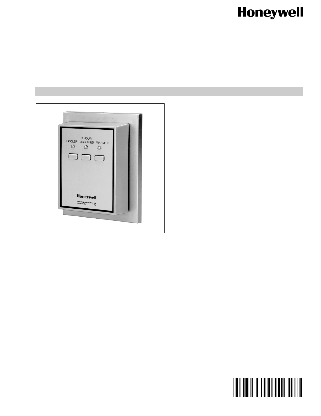
T7147
Remote Sensor
and Override Module
PRODUCT DATA
FEATURES
• Locking cover.
• Override key.
• Warmer/Cooler keys on some models.
• Key-lock override security available.
APPLICATION
The T7147 Remote Sensor and Override Module is for
use with the T7300/Q7300 Programmable Commercial
Thermostat system. The T7147 provides space temperature
sensing, switch initiation, and indication of overrides from
a remote location.
® U.S. Registered Trademark
Copyright © 2001 Honeywell • All Rights Reserved
Contents
Application ........................................................................ 1
Features ........................................................................... 1
Specifications ................................................................... 2
Ordering Information ........................................................ 2
Installation ........................................................................ 3
Wiring ............................................................................... 4
Operation .......................................................................... 6
Checkout .......................................................................... 6
63- 4065- 1
Page 2
T7147 REMOTE SENSOR AND OVERRIDE MODULE
SPECIFICATIONS
IMPORTANT
The T7147 is factory-calibrated. It does not require
field calibration and cannot be field adjusted.
1-13/16 (46)
Models:
T7147A1002 Remote Temperature Sensor & Override
Module: Connects to Q7300. Contains remote sensor,
LED and push-button switch to invoke 3 Hour Occupied
from remote location.
T7147A1010 Remote Temperature Sensor & Override
Module: Connects to Q7300. C ontains rem ote sens or , LED
and 3 push-button switc hes to invoke 3Hour Occupied and
Warmer/Cooler setpoint adjustments from remote location.
T7147A1028 Remote Temperature Sensor & Override
Module: Connects to Q7300. Same as T 7147A1010 ex cept
includes key-lock sw it ch to ena ble/disable remote ove rride
operation.
Mounting:
Mounts on wall or 2 x 4 inch verti cal outlet box w ith
screws provided.
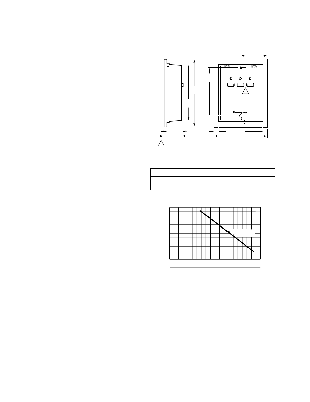
Dimensions:
See Fig. 1.
Wiring:
Maximum cable length between T7300/Q7300 and T7147:
500 ft (152 m); use 18, 20 or 22 AWG wire.
Temperature offset per 500 ft (152 m) of 2-wire sensor wire
cable (1000 ft [305 m] total length): See Table 1.
Temperature Sensor:
Thermistor-resistor (NTC) element.
Sensor Resistance:
Resistance decreases as temperature increases (Fi g. 2).
1420 ohms nominal at 75°F (24°C); resistance changes
15 ohms for each 1°F (0.6°C) temperature change.
Temperature Ratings:
Ambient: 40 to 110°F (4 to 43°C).
Shipping: -30 to +150°F (-34 to +66°C).
Humidity Ratings:
5 to 90% RH, non-condensing.
Accessories:
230492A Keys for T7147A1028.
3 HOUR
OCCUPIED
1-1/8 (29)
1-5/8 (41)
NOT ALL MODELS HAVE WARMER/COOLER FUNCTION.1
3-3/4
(96)
4-5/8
(117)
1/4
(6)
3-1/4
(83)
COOLER
2-13/16 (71)
WARMER
1
3-5/8 (92)
M17881
Fig. 1. T7147 dimensions in in. (mm).
Table 1. Temperature Offset for Remote Sensor Wiring.
Temperature Monitored 18 AWG 20 AWG 22 AWG
50 to 90°F -0.4°F -0.7°F -1.0°F
10 to 32°C -0.3°C -0.4°C -0.6°C
RESISTANCE
(OHMS)
2000
1800
1600
1400
1200
1000
10
-10
30 40 50
20
0 10
TEMPERATURE (DEGREES)
60
1420 OHMS AT
75 F (24 C)
F
70 80 90
20 30 40
100
C
M4034
Fig. 2. T7174 Remote Sensor Resistance
change with change in temperature.
ORDERING INFORMATION
When purchasing replacement and modernization products from your TRADELINE® wholesaler or distributor, refer to the
TRADELINE® Catalog or price sheets for complete ordering number.
If you have additional questions, need further information, or would like to comment on our products or services, please write or
phone:
1.
Your local Home and Building Control Sales Office (check white pages of your phone directory).
2.
Home and Building Control Customer Relations
Honeywell, 1885 Douglas Drive North
Minneapolis, Minnesota 55422-4386 (800) 328-5111
In Canada—Honeywell Limited/Honeywell Limitée, 35 Dynamic Drive, Scarborough, Ontario M1V 4Z9.
International Sales and Service Offices in all principal cities of the world. Manufacturing in Australia, Canada, Finland, France,
Germany, Japan, Mexico, Netherlands, Spain, Taiwan, United Kingdom, U.S.A.
63-4065—1 2
Page 3
T7147 REMOTE SENSOR AND OVERRIDE MODULE
INSTALLATION
When Installing this Product...
1.
Read these instructions carefully. Failure to follow
them could damage the product or cause a hazardous
condition.
2.
Check the ratings given in the instructions and on the
product to make sure the product is suitable for your
application.
3.
Installer must be a trained, experienced service
technician.
4.
After installation is complete, check out product
operation as provided in these instructions.
CAUTION
Electrical Shock or Equipment Damage Hazard.
Can shock individuals or short equipment
circuitry.
Disconnect power supply before installation.
Location
Select a location on an inside wall away from:
• drafts or dead air spots behind doors and corners.
• hot or cold air ducts.
• radiant he at from the sun or electrical equipment.
• unheated areas behind the thermostat wall.
Locate the T7147 about 5 ft (1.5 m) above the floor in an
area with good air circulation within easy reach of users.
Mounting
1.
Loosen the cover-locking screw with the Allen wrench
provided and remove the T7147 cover.
2.
Run wire to the selected location.
3.
Thread wire through T7147 base semicircular hole.
4.
Make connections to T7147 (see Wiring section).
5.
If air drafts occur through the wall opening, eliminate
them with suitable insulation material.
6.
Four mounting screws are provided:
a. 2 self-tapping type for wall mounting.
b. 2 for outlet box mounting.
7.
Select the proper screws for the application.
8.
Fasten the T7147 to the wall or outlet box with screws
through the T7147 base assembly mounting holes.
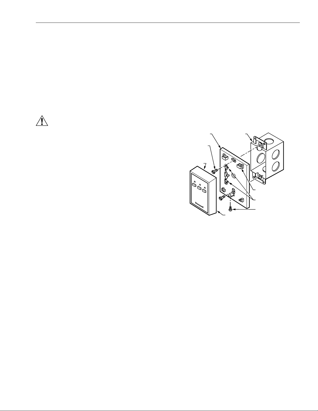
(See Fig. 3).
9.
Replace the cover assembly and tighten the coverlocking screw.
WALLPLATE
MOUNTING
SCREW (2)
MOUNTING
TAB
(2 INSIDE
COVER)
COOLER
3 HOUR
OCCUPIED
WARMER
OUTLET BOX
THERMOSTAT
MOUNTING
TAB SLOT (2)
WIRING
TERMINALS
COVER
LOCKING
SCREW
M17884
Fig. 3. Mounting the T7147.
3 63-4065—1
Page 4

T7147 REMOTE SENSOR AND OVERRIDE MODULE
WIRING
CAUTION
Erratic System Operation Hazard.
Failure to follow proper wiring practices can
introduce disruptive ele ctrica l i nterfere nce (no ise).
Keep wiring at least one foot awa y from large inductiv e
loads such as motors line starters, lighting ballasts,
and large power distribution panels.
Shielded cable is required in installations where these
guidelines cannot be met.
Ground shield only to grounded controller case.
Averaging Sensors
When the controlled zone is a large area, it can be
advantageous to use a T7147 and several remote
temperature sensors dispersed throughout the area to obtain
an average zone temperature signal. (See Fig. 6 and 7.)
NOTE: Only one T7147 can be used in any one
T7300/Q7300 system.
IMPORTANT
All wiring must comply with local codes and
ordinances.
NOTES:
— Terminal screws are provided on the device for
wiring connections.
— Wiring to device is low voltage and need not be
in conduit unless required by code.
1.
Connect correct control wires from the Q7300 subbase
to the T7147 (see Fig. 4 and 5).
2.
Ensure that Q7300 subbase switch 5 (local/remote
sensor select switch) is in the OFF position. (Refer to
the T7300/Q7300 Specification sheet, form 63-4038,
for details).
IMPORTANT
The ground (GND) connection at the T7147 is
required. Use the junction box or conduit for a
convenient grounding location.
3.
Ensure all connections are tight and secure. Loose or
intermittent wire connecti ons cause i nconsis tent syst em
operation.
4.
When installation is complete, perform the checkout
procedure (see the Checkout section).
CA5 CA4 CA3 CA2 CA1 GND
T
2
T
CONNECTIONS TO CA3 AND CA4 NOT REQUIRED
1
ON T7147A2000.
ROUTE EXCESS WIRING AWAY FROM SENSOR
2
ELEMENT FOR OPTIMUM PERFORMANCE.
CA5 CA4 CA3 CA2 CA1 GND
Fig. 4. Connecting wires to T7147.
1
M17880
63-4065—14
Page 5

T7147 REMOTE SENSOR AND OVERRIDE MODULE
T7300/Q7300
C1
C2
C3
C4
C5
T
T
Fig. 5. Typical wiring diagram for T7147 used with T7300/Q7300 Thermostat/Subbase.
T7300/Q7300
T
T
C1
C2
C3
C4
C5
CA1
T7147
WARMERCOOLER
CA2
CA3
1
CA4
CA5
WARMER/COOLER FUNCTIONS ARE
1
T
T
2
3
T7047C2007
T
T
2
T
CA1
CA2
T
CA3
CA4
CA5
T
T
GND
3
T
GND
T7047C2007
T
TT
T7047C2007T7147A
T
T
1
NOT AVAILABLE WITH THE T7147A1002.
2
SHIELDED CABLE CAN BE REQUIRED
IN SOME INSTALLATIONS.
3
THE GROUND (GND) CONNECTION TO THE T7147
IS REQUIRED. USE THE JUNCTION BOX OR CONDUIT
FOR A CONVENIENT GROUNDING LOCATION.
1
ONLY ONE T7417 ALLOWED
PER SYSTEM.
T
2
SHIELDED CABLE CAN BE
REQUIRED IN SOME INSTALLATIONS.
THE GROUND (GND) CONNECTION
3
TO THE T7417 IS REQUIRED. USE THE
JUNCTION BOX OR CONDUIT FOR A
CONVENIENT GROUNDING LOCATION.
3 HR
OCCUPIED
M10193
M10194
T7300/
Q7300
T
T
C1
C2
C3
C4
C5
Fig. 6. Wiring for T7174 used in a four-temperature sensor averaging application.
ONLY ONE T7417 ALLOWED
T7047C2007
T
T
T7047C2007
T
T
2
T
T
CA2
CA3
CA4
CA1
T
T
T
CA5
T
T
T7147A
GND
3
T7047C2007
T
T7047C2007
T
T7047C2007
T
TT
1
T7047C2007
T
T
T
T
T
TT
T
T
T7047C2007
T7047C2007
TT
1
PER SYSTEM.
2
SHIELDED CABLE CAN BE
REQUIRED IN SOME INSTALLATIONS.
3
THE GROUND (GND) CONNECTION
TO THE T7417 IS REQUIRED.
USE THE JUNCTION BOX OR
CONDUIT FOR A CONVENIENT
GROUNDING LOCATION.
Fig. 7. Wiring for T7174 used in a nine-temperature sensor averaging application.
5 63-4065—1
M10195
Page 6

T7147 REMOTE SENSOR AND OVERRIDE MODULE
OPERATION
Sensor
The remote sensor control element is a negative temperature
coefficient (NTC) thermistor. As room temperature increases,
the resistance of the thermistor decreases. As room
temperature decreases, the resistance of the thermistor
increases. The T7300 detects the thermistor resistance
change and controls the space temperature by sequentially
staging the heating/cooling equipment on and off.
NOTE: The T704 7C 10 25 use s the sa me se nso r elem ent .
3 Hour Occupied
When correctly wired, pressing the
sends a signal from the T7147 to the T7300/Q7300. Upon
receipt of this signal, the T7300/Q7300 proceeds into the
3 Hour Occupied override. In response, the T7300/Q7300
sends a signal back to the T7147 to turn on the 3 Hour
Occupied LED. The 3 Hour Occupied LED remains on for
the duration of the 3 hour override.
NOTE: For addit ion al det ail s, con su lt the T730 0/Q 73 00
Specification sheet, form 63- 4038.
3 Hour Setpoint Adjust
When wired correctly, pressing the
followed by th e
T7147 to the T7300/Q7300. The T7300/Q7300, upon receipt
of this signal, proceeds into the 3 Hour Setpoint Adjust
override. In response, the T7300/Q7300 sends a signal back
to the T7147 that turns on the 3 Hour Occupied LED and the
appropriate Warmer or Cooler LED. The 3 Hour Occupied
LED and Warmer or Cooler LED remains on for the duration
of the 3 hour override.
Warmer
or
Cooler
3 Hour Occupi ed
3 Hour Occupied
key sends a signal from the
key
key,
CHECKOUT
1.
Allow the sensor to stabilize to ambient conditions
before taking a resistance measurement. The sensor
resistance measurement should be in accordance with
the device temperature curve (see Fig. 2).
2.
Check operation of the
a. Press the
b. The LED above the key turns on.
3.
Go to the T7300 thermostat an d ch ec k it to s ee tha t the
display arrow indicator points to
4.
On models with
a. Press the
b. The LED above the
c. Press the
d. The LED above the
LED above the
e. Press the
f. The LED above this key turns off, as well as those
5.
6.
above either the
Go to the T7300 thermostat and check to see that the
arrow indicator on the display no longer points to
Occupied
occupied or unoccupied period.
NOTE: If the T7147 does not check out, review the
Check operation of the complete control system as
directed in the T7300/Q7300 Specification sheet, form
63-4038.
3 Hour Occupied
Warmer
Cooler
3 Hour Occupied
and has returned to its c urre ntly p rogra mm ed
wiring and connections between the Q7300
and the T7147. Replace the T7147 if wiring
continuity checks out. If the new T7147 does
not check out, replace the Q7300.
3 Hour Occupied
Warmer
key once.
Warmer
key.
Warmer
Cooler
Warmer
key once.
3 Hr Occupied
Cooler
and
key comes on.
key turns off and the
key turns on.
key once.
Cooler
or
key:
keys:
keys.
.
3 Hr
This override may be performed at any time, regardless of
whether the thermostat system is operating in the occupied
or unoccupied mode.
NOTES:
— For additional details, con sult the T730 0/Q 73 00
Specification sheet, form 63- 4038.
— Premature exit from either override can be
achieved by pressing the
again. The T7300 then returns to normal operation.
3 Hour Occupied
key
63-4065—16
Page 7

7 63-4065—1
Page 8

Printed in U.S.A. on recycled
paper containing at least 10%
post-consumer paper fibers.
Home and Building Control Home and Building Control Honeywell Asia Pacific Inc. H oneywe ll Europe S.A. H oneywe ll Latin Americ an
Honeywell Honeywell Limited-Honeywell Limitée Room 3213-3225 3 Avenue du Bourget
1985 Douglas Drive North 35 Dynamic Drive Sun Hung Kai Centre 1140 Brussels 480 Sawgrass Corporate Parkway
Golden Valley, MN 55422 Scarborough, Ontario No. 30 Harbour Road Belgium Suite 200
M1V 4Z9 Wanchai Sunrise FL 33325
Hong Kong
Region
63-4065—1 B.B. Rev. 3-01 www.honeywell.com
 Loading...