

Page 1
T7100F Microelectronic Conventional
69-0964-2
or Heat Pump Thermostat
INSTALLATION INSTRUCTIONS
APPLICATION
The T7100F Microelectronic Thermostat provides
electronic control of 24 Vac commercial single
zone heating, ventilating and air conditioning
(HVAC) equipment. It is designed for use with the
Q7100A Subbases for conventional heat/cool
applications and the Q7100C Subbases for heat
pump applications. The T7100F is field
configurable for automatic or manual changeover
between heating and cooling. All T7100F
Thermostats require a common wire to supply
power.
NOTE: When Q7100C Subbases are used, Installer
Setup Option must be set to 01 (heat pump).
RECYCLING NOTICE
If this control is replacing a control that contains
mercury in a sealed tube, do
control in the trash.
Contact your local waste management authority for
instructions on recycling and the proper disposal of
the old thermostat.
not
place your old
INSTALLATION
When Installing this Product...
1. Read these instructions carefully. Failure to follow
the instructions can damage the product or cause a
hazardous condition.
2. Check ratings given in instructions and on product to
make sure product is suitable for your application.
3. Installer must be a trained, experienced service
technician.
4. After completing installation, use these instructions
to check out the product operation.
Mounting and Wiring Q7100 Subbase
Refer to the subbase installation instructions for mounting
and wiring information.
Setting Keypad Lockout Switch
The T7100F can be configured for keypad lockout to
prevent changes to the temperature or system settings.
DIP switch number 1, on the back of the thermostat,
activates the lockout feature. See Fig. 1. The DIP switch
must be set to the ON position (up) to activate the lockout
feature. The factory setting is off (down). Be sure to set the
switch before mounting the thermostat on the subbase.
When the DIP switch is set to the ON position it disables
all of the keys on the thermostat.
ON
1
1
2
DIP 1 IS ON
1
BACK OF THERMOSTAT
Fig. 1. Setting keypad lockout DIP switch
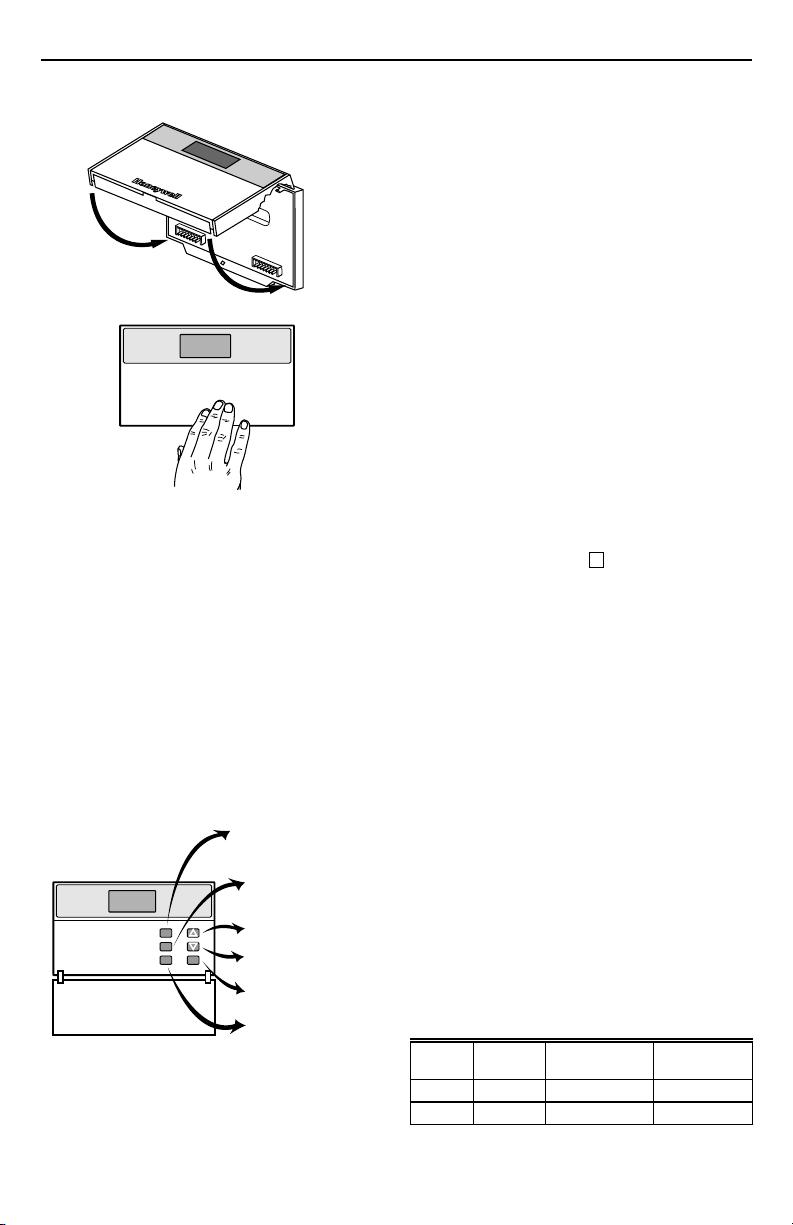
Mounting Thermostat
Mount the thermostat on the Q7100 Subbase after the
Q7100 is installed:
1. Engage tabs at the top of the thermostat and
subbase. Fig. 2.
2. Press lower edge of the case to close and latch.
(back of thermostat).
M10108
CAUTION
Electrical Hazard.
Can cause electrical shock or equipment damage.
Disconnect power supply before installation.
X-XX UL
Page 2
T7100F MICROELECTRONIC CONVENTIONAL OR HEAT PUMP THERMOSTAT
A.
ENGAGE TABS AT TOP OF THERMOSTAT AND SUBBASE.
B.
PRESS LOWER EDGE OF CASE TO LATCH.
M6799A
Fig. 2. Mounting thermostat on subbase.
NOTE: To remove the thermostat from the wall, first pull
out at the bottom of the thermostat; then remove
the top.
Using Thermostat Keys
The thermostat keys are used to:
• Set temperature,
•Display present setting,
• Configure Installer Setup,
• Check Self-Test.
Select models have keys to:
• Temporarily override the temperature,
• Set the system operation,
• Set the fan operation.
See Fig. 3 for key information.
DISPLAY PRESENT SETTINGS
AND SCROLL THROUGH
INSTALLER SETUP
(INFORMATION KEY)
CHANGE TEMPERATURE
SETTING TEMPORARILY
(SELECT MODELS)
i
INCREASE TEMPERATURE
SETTING
DECREASE TEMPERATURE
SETTING
SELECT
FAN OPERATION
SELECT SYSTEM
OPERATION
M6800B
Fig. 3. Thermostat key locations and descriptions.
SETTINGS
System and Fan Settings
System settings control the thermostat operation as
follows:
Em Heat (Q7100C only): Emergency heat relay is on
continuously. Thermostat cycles highest stage of
heat. Cooling system is off. Compressor is de-
energized.
Heat: Thermostat controls the heating.
Off: Both the heating and cooling are off.
Cool: Thermostat controls the cooling.
Auto: Thermostat automatically changes between
heating and cooling operation, depending on the
indoor temperature.
Fan settings control the system fan as follows:
On: Fan operates continuously.
Auto: Equipment controls fan.
The system default setting is Heat and the Fan default
setting is Auto. Use the keys to change to the desired
settings.
Temperature Settings
The default setpoint for heat is 70°F (21°C) and for cool is
78°F (25.5°C). Press the increase ▲ or decrease ▼ key to
change the setting. To change between heat and cool
settings, press the Information i key until the setting to
be changed appears.
Override Temperature Settings
(Select Models)
The T7100 temperature settings can be overridden in
three ways:
— Using the T7100 Override key, acting as a toggle.
— Using a remote setback timer.
— Using an occupancy sensor.
The temperature settings change based on Installer
Setup 27.
NOTE: Installer Setup 27 is factory set at zero degrees
so this setting must be changed for the temperature to change.
The Override key changes the current temperature
temporarily to a preset offset. The remote timer and
occupancy sensor open (temporary setpoint) or close
(comfort setpoint) contacts according to the settings. See
Table 1.
Always check the display to determine if the thermostat is
controlling the comfort, temporary or remote setpoints.
Temporary is displayed when the Override key is pressed
or the occupancy sensor or remote setback timer is
energized.
Table 1. Temperature override.
System
Setting
Comfort
Setpoint
Installer Setup
27 Setting
Heat 68°F10°F58°F
Cool 74°F10°F84°F
Temporary
Setpoint
69-0964–2
2
Page 3

T7100F MICROELECTRONIC CONVENTIONAL OR HEAT PUMP THERMOSTAT
INSTALLER SETUP
NOTE: For most applications, the thermostat factory
settings do not need to be changed. Review the
factory settings in Table 2 and if no changes are
necessary go to the Installer Self-Test section.
The Installer Setup is used to customize the thermostat to
specific systems. Some of the options include temperature
display, remote sensing system, changeover, minimum
equipment On time and minimum Off time. Installer modes
are listed in numerical order in Table 2. It includes all the
configuration options and the factory-settings available for
the T7100F.
IMPORTANT
The Installer Setup must be set correctly for the
HVAC equipment, thermostat and subbase to
operate properly.
A combination of key presses are required to use the
Installer Setup feature:
— To enter the Installer Setup mode, press and hold the
Information i key with the increase ▲ and decrease
▼ keys until the first mode number is displayed. All
display segments appear for approximately three
seconds before the first mode number is displayed.
See Fig. 4 and 5.
— To advance to the next Installer Setup mode, press
the Information i key.
— To change a setting, use the increase ▲ or decrease
▼ key.
— To exit the Installer Setup mode, press and hold the
Information i key until the display returns to normal
(approximately three seconds). The display scrolls the
mode numbers backward to get to the normal display.
The Installer Setup mode is automatically exited if no
key presses are made for five minutes.
Em Ht Temporary Setting
Aux Ht
Repl
Wait
Batt
System Fan
Em HeatOffCool Auto Only
Heat Cool
Fig. 4. Display of all LCD segments.
MODE NUMBER DISPLAY
(COLUMN 2 OF TABLE 2)
Fig. 5. Display of Installer Setup mode and setting.
CAUTION
Equipment Damage.
Damage can result when the system runs
without the fan.
Configure heat pump and electric heat systems
correctly in Installer Setup modes 01 and 02.
NOTE: Only configurable Mode Numbers are shown.
Remote
Room
%Humid
Outdoor
OnAuto
M4844
FACTORY SETTING OR
OTHER CHOICE DISPLAY
(COLUMN 3 OR 5 OF TABLE 2)
M10105
Table 2. Thermostat Installer Setup Options.
Mode Number
(Press i key
Select
to change)
Application. 01 00 Conventional equipment
Fan operationa.0200Conventional applica-
Output stages of
heating.
03 Depends
Factory-Setting
Display Description Display Description
application (Q7100A).
tions where equipment
controls fan operation in
heat mode.
on
subbase.
Stages of heat. 01, 02, or0301—One stage of heat.
01 Heat pump application (Q7100C,D)
01 Electric heat applications where
Other Choices
(Press ▲ or ▼ key to change)
(fan operation is automatically
selected so go to mode number
03).
thermostat controls fan operation
in heat mode.
02—Two stages of heat.
03—Three stages of heat.
Heating cycle 04 Depends Stage 1. 03, 04, 03—3 cph used for hot water
rate. 05 on model Stage 2. 06, 08 systems or high efficiency
06 Stage 3 (Q7100C only). or 09 furnaces.
07 Emergency heat
a
Mode 01 must be 00 to allow a selection in this mode.
(Q7100C only).
04—4 cph (factory setting for heat
pump systems).
06—6 cph used for conventional
systems.
08—8 cph (factory setting for
conventional systems).
09—9 cph used for electric heat
systems and is the factory setting
for the emergency heat stage.
(continued)
3
69-0964–2
Page 4

T7100F MICROELECTRONIC CONVENTIONAL OR HEAT PUMP THERMOSTAT
Table 2. Thermostat Installer Setup Options (Continued).
Select
Output stages
of cooling.
Mode Number
(Press i key
to change)
08 02 Two stages of cool. 00 or 01 00—No cooling.
Factory-Setting
Display Description Display Description
Cooling cycle rate. 09 04 Stage 1. 03 3 cph.
10 04 Stage 2.
Not used. 11 — — — —
Changeover
(T7100F only).
12 00 System setting key is
operational.
01 or 02 01—Manual changeover
Not used. 13 — — — —
Degree tempera-
ture display.
Displaying
temperature.
14 00 Temperature is
15 00 Temperature is
displayed in °F.
displayed.
01 Temperature is displayed in °C.
01 Temperature is not displayed.
Not used. 16 - 18 — — — —
Extended fan
operation in
b
heating
.
Extended fan
operation in
cooling.
Fan key
adjustment.
Remote sensing. 22 00 Remote sensing not
Temperature
averaging
c
network
.
19 00 No extended fan
20 00 No extended fan
21 00 Fan setting key is
operation after the call
for heat ends.
operation after the call
for cool ends.
operational.
activated.
23 00 Temperature averaging
disabled.
01 Fan operation is extended
01 Fan operation is extended
01 Fan setting key is continuously in
01 Remote sensing activated.
01 Temperature averaging between
Not used. 24 — — — —
Keypad lockout
level.
25 0 No lockout. 01 - 02 01—View setpoint only.
Not used. 26 — — — —
Heating/cooling
override.
27 00 No temperature change
when override key is
pressed.
01 - 15 °F the temperature setting is
Not used. 28 - 29 — — — —
Deadband. 30 02 Heating and cooling
Interstage control
point (select
models).
31 01
(Conventional) or
02 (Heat
pump).
Minimum On time. 32 02 2-minute minimum On
Minimum Off time
for the
compressor.
b
Mode 01 or 02 must be 01 to extend fan operation.
c
Mode 22 must be set to 01 and remote sensor(s) must be installed.
33 04 4-minute minimum Off
setpoints can be set no
closer than 2°F.
Temperature has to
change 1°F or 2°F
before the system calls
for the next stage.
time for heating and
cooling.
time for the compressor.
03 - 10 Heating and cooling setpoints can
00 - 12 Temperature has to change the
00 or 01 No minimum On time or 1 minute
00, 01,
02, 03 or
05
Other Choices
(Press ▲ or ▼ key to change)
01—One stage of cool.
02—Auto only.
90 seconds after the call for
heat ends.
90 seconds after the call for
cool ends.
the Auto position.
local sensor and remote sensor(s)
activated.
02—Lockout all keys.
changed when the override key is
pressed. Temporary is displayed.
be set no closer than the chosen
value.
chosen value before the system
calls for the next stage.
minimum On time for heating and
cooling.
Minimum number of minutes (0
thru 5) the compressor will be off
between calls for the compressor.
(continued)
69-0964–2
4
Page 5

T7100F MICROELECTRONIC CONVENTIONAL OR HEAT PUMP THERMOSTAT
Table 2. Thermostat Installer Setup Options (Continued).
Mode Number
(Press i key
Select
Temperature
range stops in
heating (T7100F
only).
Temperature
range stops in
cooling (T7100F
only).
to change)
34 90 Highest heating setpoint
35 45 Lowest cooling setpoint
Not used. 36 — — — —
Temperature
display
adjustment.
Minimum Off
times in heating.
37 00 No difference in
38 02 2-minute minimum Off
Factory-Setting
(Press ▲ or ▼ key to change)
Display Description Display Description
allowed.
allowed.
displayed temperature
and actual room
temperature.
time.
40 - 89 Temperature range for (1°F
46 - 99 Temperature range for (1°F
01 - 06
00, 01,
03, 04 or
05
Other Choices
increments) heating setpoint.
increments) cooling setpoint.
01—Display adjusts to 1°F higher
than actual room temperature.
02—Display adjusts to 2°F higher
than actual room temperature.
03—Display adjusts to 3°F higher
than actual room temperature.
04—Display adjusts to 1°F lower
than actual room temperature.
05—Display adjusts to 2°F lower
than actual room temperature.
06—Display adjusts to 3°F lower
than actual room temperature.
Minimum number of minutes (0
thru 5) the heating equipment is off
between calls for heat.
INSTALLER SELF-TEST
Use the Installer Self-Test to check the thermostat
configurations and operation. Refer to Table 3 for a list of
the available Self-Tests.
NOTE: The minimum Off time for compressors is
bypassed during the Installer Self-Test.
To start the Self-Test:
Press and hold the increase ▲ and decrease ▼ keys, at
the same time, until two zeros appear. All segments of
the LCD are displayed for three seconds before the two
zeros appear. Refer to Fig. 6 and 7.
Em Ht Temporary Setting
Aux Ht
Repl
Wait
Batt
System Fan
Em HeatOffCool Auto Only
Heat Cool
Fig. 6. Display of all LCD segments.
Remote
Room
%Humid
Outdoor
OnAuto
M4844
TEST MODE
NUMBER
Fig. 7. Display of Test Mode number.
Table 3. Installer Self-Test Mode Tests.
Test
Number Self-Test Description
10-19 Heating equipment can be turned on and off.
20-29 Emergency heat (Q7100C only) equipment
can be turned on and off.
30-39 Cooling equipment can be turned on and off.
40-49 Fan equipment can be turned on and off.
60-69 Keyboard keys test.
70-79 Thermostat information including date code
and software versions is displayed.
Refer to Table 4 for the directions and results of the
specific tests.
NOTE: Press and hold the increase ▲ and decrease ▼
keys for three seconds to exit the Self-Test
mode. Self-Test times out after five minutes
without any key presses.
5
M6792
69-0964–2
Page 6

T7100F MICROELECTRONIC CONVENTIONAL OR HEAT PUMP THERMOSTAT
Table 4. Installer Self-Test Options.
Key to
Press
Heating Equipment Self-Test
▲ 11 Stage-one heat comes on. When Installer Setup mode number 01 is 01 or mode number 02
▲ 12 Stage-two heat comes on. Stage-one heat and system fan remain on.
▲ 13 Stage-three heat comes on (heat pump configuration). Stage-one and stage-two heat remain
▼ 12 Stage-three heat turns off.
▼ 11 Stage-two heat turns off.
▼ 10 Stage-one heat and system fan turn off.
Emergency Heating Equipment Self-Test (with select Q7100C Subbase models)
▲ 21 Emergency heat comes on.
▼ 20 Emergency heat turns off.
Cooling Equipment Self-Test
▲ 31 Stage-one cooling and system fan come on.
▲ 32 Stage-two cool comes on. Stage-one cool and system fan remain on.
▼ 31 Stage-two cool turns off.
▼ 30 Stage-one cool and system fan turn off.
Fan Equipment Self-Test
▲ 41 Fan comes on.
▼ 40 Fan turns off.
KEY TEST
▲ 60 Displays 4.
▼ 60 Displays 3.
Override 60 Displays 5.
System
Fan
a
Available on select models.
Test
Mode
Number Description
i
10 Enter heating equipment Self-Test.
is 01, the system fan is also energized.
on.
i
i
i
i
20 Change from heating to emergency heating equipment Self-Test.
30 Change from heating or emergency heating to cooling equipment self-test.
40 Change from cooling to fan equipment Self-Test.
a
60 Displays 2.
a
60 Displays 0.
a
60
Displays 1.
Thermostat Information
1. Press the Information i key to access the thermo-
stat information.
M4864
69-0964–2
2. Press the increase ▲ key to display the production
date code. The first two large digits are the month
and the third digit is the last digit of the year.
(Example: 026 = February 1996)
6
M4865
Page 7

T7100F MICROELECTRONIC CONVENTIONAL OR HEAT PUMP THERMOSTAT
3. Press the increase ▲ key again to display the
software identification code.
(Example: 02 = software ID code 2)
M4866
4. Press the increase ▲ key again to display the
software revision number.
(Example: 001 = revision number 1)
M6787
5. Press the increase ▲ key again to display the
EEPROM identification code.
(Example: 222 = EEPROM ID 222)
6. Press and hold both the increase ▲ and the
decrease ▼ keys, until the room temperature is
displayed, to exit the Self-Test. The Self-Test times
out after five minutes without any key presses.
TROUBLESHOOTING GUIDE
Symptom Possible Cause Action
Display does not
come on.
Temperature
display is incorrect.
Temperature
settings will not
change. (Example:
Cannot set
higher or cooling
lower.)
Thermostat is not powered. • Check that X terminal is connected to the system
Thermostat microprocessor is
locked up.
Room temperature display has
been reconfigured.
Thermostat is configured for °F
or °C display (select models).
transformer.
• Check for 24 Vac between X and R or RH terminals.
— If missing 24 Vac:
— Check if the circuit breaker is tripped—reset the
circuit breaker.
— Check if the system fuse is blown—replace the
fuse.
— Check if the power switch on the HVAC equipment
is in the Off position—set to the On position.
— Check the wiring between the thermostat and the
HVAC equipment—replace any broken wires and
tighten any loose connections.
— If 24 Vac is present, proceed with troubleshooting.
Remove the thermostat from the subbase for 2 minutes. After
2 minutes, replace the thermostat on the subbase.
Enter Installer Setup 37 and reconfigure the display.
Enter Installer Setup 14 and reconfigure the display.
Bad thermostat location. Relocate the thermostat.
Display shows two dashes and
a degree sign.
Upper or lower temperature
limits were reached.
heating
Installer Setup 22 is set for remote sensing and the sensor is
missing or the circuit is open or shorted.
Check the temperature setpoints:
• Heating limits are 40 to 90°F (7 to 31°C).
• Cooling limits are 45 to 99°F (9 to 37°C).
M6788
(continued)
7
69-0964–2
Page 8

T7100F MICROELECTRONIC CONVENTIONAL OR HEAT PUMP THERMOSTAT
TROUBLESHOOTING GUIDE (Continued)
Symptom Possible Cause Action
Heating does not
come on.
Cooling does not
come on.
Cooling does not
come on
(continued)
System On
indicator is lit, but
no heat is being
delivered.
24V is present on
all terminals.
No power to the thermostat. • Check that X terminal is connected to the system
Thermostat minimum Off time is
activated and wait indicator is
displayed.
System selection is not set to
Heat.
No power to the thermostat. • Check that the X terminal is connected to the system
Thermostat minimum Off time is
activated and wait indicator is
displayed.
System selection is not set to
Cool.
Fan operation set to 00
(conventional heat) when it
should be set to 01 (electric
heat).
Conventional heating
equipment turns on the fan
when the furnace has
warmed up to a setpoint.
Heating equipment is not
operating.
When thermostat is powered
but is not connected to
heating/cooling equipment, arc
suppression will be present
(24V ghost voltage)
transformer.
• Check for 24 Vac between X and R or RH terminals.
— If missing 24 Vac:
— Check if the circuit breaker is tripped—reset the
circuit breaker.
— Check if the system fuse is blown—replace the
fuse.
— Check if the system switch at the equipment is in
the Off position—set to On position.
— Check wiring between the thermostat and the
HVAC equipment—replace any broken wires and
tighten any loose connections.
— If 24 Vac is present, proceed with troubleshooting.
• Wait up to five minutes for the system to respond.
• Enter Installer Setup 38. Reconfigure minimum On time (if
required).
Set system selection to Heat.
transformer.
• Check for 24 Vac between X and R or RC and Y terminals.
— If missing 24 Vac:
— Check if the circuit breaker is tripped—reset the
circuit breaker.
— Check if the system fuse is blown—replace the
fuse.
— Check if the system switch at the equipment is in
the Off position—set to the On position.
— Check wiring between thermostat and HVAC
equipment—replace any broken wires and tighten
any loose connections.
— If 24 Vac is present, proceed with troubleshooting.
• Wait up to five minutes for the system to respond.
• Enter Installer Setup 33. Reconfigure minimum Off time (if
required).
Set system selection to Cool.
Enter Installer Setup mode number 02 and reconfigure the fan
operation.
Wait a minute after seeing the On indicator and then check the
registers.
Verify operation of heating equipment in Self-Test.
Connect heating/cooling equipment to the thermostat. Voltage
will drop to zero.
69-0964–2
69-0964–2 D.S. Rev. 12-98 Printed in Taiwan R.O.C. www.honeywell.com/building/components
8
 Loading...