

Page 1
Put UPC Code Here
T7079A,B
Solid State
Remote Temperature Controllers
PRODUCT DATA
FEATURES
• Switch selection of heat or cool mode.
• Temperature sensing up to 400 feet.
• Does not require field calibration.
• 10K NTC temperature sensor.
• Wide setpoint temperature range.
• LED annunciation for both power on and relay state.
• Dual setpoint scale (°F and °C).
• Isolation transformer for 24 Vac input.
• Single- or Dual-stage output.
• Dual-stage output models can be configured as
two-heat, two-cool, or one-heat/one-cool.
APPLICATION
The T7079 Electronic Remote Sensor Temperature Controller
is capable of providing on-off temperature control for ducts,
tanks, heating and refrigeration units, greenhouses, animal
confinement buildings and other applications where electronic
accuracy in addition to remote sensing is desired.
Contents
Application ........................................................................1
Features ...........................................................................1
Specifications ....................................................................2
Ordering Information .........................................................2
Installation ........................................................................3
Wiring ...............................................................................4
Operation ..........................................................................5
Checkout ..........................................................................6
63-2572—04
Page 2

T7079A,B SOLID STATE REMOTE TEMPERATURE CONTROLLERS
SPECIFICATIONS
Models:
T7079: On-off wall-mount control with one temperature input
and one or two relay output stages. Differential range of
1 to 30°F. Includes one sensor. See Table 1.
Table 1. T7079 models.
Voltage (in Vac) Setpoint Range in °F (°C)
-25 to 105
24 120/230
(-32 to 40)
T7079A1004 X X
T7079A1012 X X
T7079A1046 X X
T7079A1053 X X
T7079B1028 X X
T7079B1036 X X
T7079B1044 X X
T7079B1051 X X
Dimensions: See Fig. 1.
2 (50)
1 (25)
2-7/16 (61)
2 (50)
2-7/16 (61)
STAGE1 STAGE2 POWER
100 to 240
(38 to 116)
Power Consumption: See Table 2.
Table 2. Power consumption ratings.
Vol tage Hz No m i n a l VA M a x imum VA
24 50 5.6 6.2
60 5.5 6.1
120 50 7.7 8.5
60 5.6 6.2
230 50 5.0 6.1
60 2.9 4.7
Contact Ratings:
At 120 Vac: 1/2 hp, 9.8 FLA, 58.8 LRA.
At 230 Vac: 1/4 hp, 4.9 FLA, 29.4 LRA.
At 120/230 Vac: 125 VA pilot duty.
At 24 Vac (resistive): 8A.
Ambient Ratings:
Operating Temperature: -40° to 140°F (-40° to 60°C).
Storage Temperature: -40° to 180°F (-40° to 82°C).
Operating Humidity: 5% to 95% RH non-condensing.
Temperature Accuracy (at nominal voltage): In 77°F
(25°C) ambient, nominal sensor value: ±2°F.
NOTE: Accuracy can vary based on deviation from nominal
values of input voltage, operating ambient and
sensor ambient.
Sensor: 10k NTC, 400 ft maximum distance between sensor
and electronic controller. See Table 3 for thermistor output.
Approvals:
Underwriters Laboratories, Inc.
Canadian Underwriters Laboratories.
CE.
4-1/2
(114)
7-3/16
(183)
Accessories:
107048 Heat Conduction Compound, 4 once.
107324A Bulb Holder, duct insertion.
M17560
Fig. 1. Dimensions of T7079 in in. (mm).
121371A Copper Immersion Well.
121371E Stainless Steel Well.
32004800-001 10K NTC Sensor.
T7047C1090 Wall Mounted Sensor Case.
Electrical Ratings:
Voltage Input: 24 Vac, 50/60 Hz (+10%, -15%), Class 2 only.
120/230 Vac, 50/60 Hz (+10%, -15%).
ORDERING INFORMATION
When purchasing replacement and modernization products from your TRADELINE® wholesaler or distributor, refer to the
TRADELINE® Catalog or price sheets for complete ordering number.
If you have additional questions, need further information, or would like to comment on our products or services, please write or
phone:
1. Your local Honeywell Automation and Control Products Sales Office (check white pages of your phone directory).
2. Honeywell Customer Care
1885 Douglas Drive North
Minneapolis, Minnesota 55422-4386
In Canada—Honeywell Limited/Honeywell Limitée, 35 Dynamic Drive, Toronto, Ontario M1V 4Z9.
International Sales and Service Offices in all principal cities of the world. Manufacturing in Australia, Canada, Finland, France,
Germany, Japan, Mexico, Netherlands, Spain, Taiwan, United Kingdom, U.S.A.
63-2572—04 2
Page 3
T7079A,B SOLID STATE REMOTE TEMPERATURE CONTROLLERS
CAUTION
Table 3. 10K thermistor output.
Resistance °C °F
97820 -20 -4
32740 0 32
19920 10 50
12500 20 68
10000 25 77
8056 30 86
5326 40 104
3604 50 122
2491 60 140
1756 70 158
1261 80 176
920.9 90 194
INSTALLATION
When Installing this Product...
1. Read these instructions carefully. Failure to follow
them could damage the product or cause a hazardous
condition.
2. Check the ratings given in the instructions and on the
product to make sure the product is suitable for your
application.
3. Installer must be a trained, experienced service
technician.
4. After installation is complete, check out product
operation as provided in these instructions.
IMPORTANT
All wiring must agree with applicable codes,
ordinances and regulations.
Sensor Location
The sensor can be located up to 400 feet (122 meters) from
the T7079 using standard AWG 18/2 unshielded wire. The
sensor may be attached to pipes, in an immersion well, in a
wall-mounted case or on a bulb holder.
NOTES:
— For cable runs greater than 25 feet, shielded cable
is recommended.
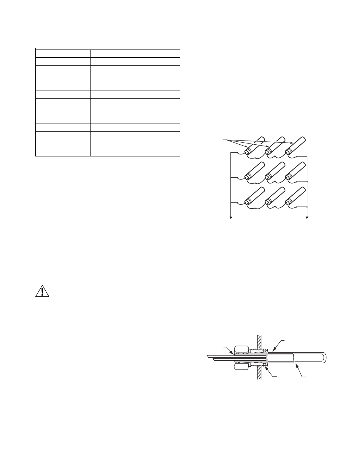
— Multiple sensors can be parallel-series wired to
sense average temperatures in large spaces.
See Fig. 2.
— To maintain control accuracy, the number of
sensors wired parallel-series must be n
2
(examples: 4, 9, 16).
SENSORS
TO T7079
M13129
Fig. 2. Parallel-series wiring of sensors.
Sensor Mounting
IMPORTANT
The T7079 is an operation control, not a limit or safety
control. If used in applications requiring safety or limit
controls, use a separate safety or limit control device
in conjunction with the T7079.
Electrical Shock or Equipment Damage Hazard.
Can shock individuals or short equipment
circuitry.
Disconnect power supply before installation.
Location and Mounting
Mount the controller on a convenient interior location using the
three mounting holes provided on the back of the enclosure
(mounting screws are not provided and must be obtained
separately). Use controller dimensions in Fig. 1 as a guide.
Mount the sensor(s) in one of the following manners:
— Hot/cold water sensing: Strap sensor to a pipe or insert in a
well (see Fig. 3).
— Space temperature sensing: Mount on a wall or panel
(see Fig. 4).
— Duct air sensing: Tape to a standard cap or bulb holder.
COVER SENSOR
LEADS WITH
HEAT CONDUCTIVE
COMPOUND
SENSOR PLACED
IN WELL
1/2 NPT
IMMERSION
WELL
M5249
Fig. 3. Sensor inserted in an immersion well.
3 63-2572—04
Page 4

T7079A,B SOLID STATE REMOTE TEMPERATURE CONTROLLERS
CAUTION
M13130
SENSOR
T7047C1090
WALLMOUNT SENSOR
CASE (OPTIONAL)
CAUTION: POSITION SENSOR AWAY
FROM SCREW TERMINALS.
SCREW
TERMINAL
SCREW
TERMINAL
LEADWIRES
TO T7079
STAGE 1 LED
SENSOR
TERMINALS
STAGE DIFFERENTIAL
ADJUSTMENTS
INTERSTAGE
DIFFERENTIAL
VOLTAGE INPUT
OUTPUT STAGE
SWITCHING
1
SENSOR
J1
COOL
HEAT
1
STAGE 2 LED POWER LED
LD1
LD2
DIFF2
1
DIFF1
INTER
J2
PWR
2
24 VAC
Fig. 4. Wall-mounted sensor.
WIRING
Electrical Shock or Equipment Damage Hazard.
Can shock individuals or short equipment
circuitry.
Disconnect power supply before installation.
Refer to Fig. 5 for locating the appropriate power input, remote
sensor input and stage output terminals. To access the
terminals, remove the four cover screws and lift off the cover.
Refer to Fig. 6 and 7 for typical wiring.
IMPORTANT
Erratic temperature readings from the sensor can be
caused by poor wiring practices that must be avoided
to ensure proper operation:
1. Do not route the temperature sensor wiring with building power wiring.
2. Do not locate the temperature sensor wiring next to
control contactors.
3. Do not locate the temperature sensor wiring near
electrical motors.
4. Do not locate the temperature sensor wiring near
welding equipment.
5. Make sure good mechanical connections are made to
both the sensor and the control.
6. Use 90°C copper wire.
1
J5 J4 J3
NC NO NOCOM NC COM COM120V240V
1 3
TWO-STAGE MODELS ONLY.
2
LOW-VOLTAGE MODELS ONLY.
LINE-VOLTAGE MODELS ONLY.
M17561
Fig. 5. Board layout for T7079.
NOTES:
1. The larger conduit knockout on the enclosure
bottom is for line-voltage applications.
2. The smaller knockout on the enclosure bottom is
for low-voltage applications.
3. The sensor knockout is at the enclosure top.
SENSOR
J2
J1
J5 J4
NC NO NOCOM NC COM
STAGE 2
LED
STAGE 1
LED
M17562
L1
(HOT)
24 VAC
L2
Fig. 6. Typical low-voltage (24 Vac) wiring application.
3
63-2572—04 4
Page 5

T7079A,B SOLID STATE REMOTE TEMPERATURE CONTROLLERS
SENSOR
J1
J5 J4
NC NO NOCOM NC COM COM120V240V
STAGE 2
LED
L2
STAGE 1
LED
L1
(HOT)
M17563
Fig. 7. Typical line-voltage (120 Vac) wiring application.
OPERATION
Control Algorithm
On/Off Control
When used in heating mode, the relay is:
— Energized at setpoint minus differential on temperature fall.
— De-energized at setpoint on temperature rise.
When used in cooling mode, the relay is:
— Energized at setpoint plus differential on temperature rise.
— De-energized at setpoint on temperature fall.
NOTE: Each stage LED lights when its stage is energized.
The power LED lights when the controller is
connected to 120/230 or 24 Vac.
DIFF2
ST2
COOL
HEAT
ST1
10
0
10
1
25
35
INTER
20
30
11030
DIFF1
20
M17573
Fig. 8. Adjustments (potentiometers and switches).
TWO-STAGE HEAT
1. Set ST1 and ST2 switches to HEAT.
2. Set interstage (INTER) and differential (DIFF1, DIFF2) to
desired settings.
3. Position the setpoint knob at the setting for stage 1.
TWO-STAGE COOL
1. Set ST1 and ST2 switches to COOL.
2. Set interstage (INTER) and differential (DIFF1, DIFF2) to
desired settings.
3. Position the setpoint knob at the setting for stage 1.
ONE-STAGE HEAT/ONE-STAGE COOL
1. Set ST1 switch to HEAT and ST2 switch to COOL.
2. Set interstage (INTER) and differential (DIFF1, DIFF2) to
desired settings.
3. Position the setpoint knob at the setting for stage 1.
NOTE: See Fig. 9 for an example setup.
Differential (Stage and Interstage)
Adjustment
The stage and interstage differential values are adjusted using
the internal potentiometers (see Fig. 8). Values for setting are
marked on the inside cover:
— Minimum stage differential (DIFF1 or DIFF2): 1°F.
— Interstage differential: 0°F to 35°F.
NOTES:
— Actual minimum differential is typically between
1°F and 4°F. It is influenced by device tolerances
and the rate of temperature change.
— The setpoint knob setting is the stage 1 setpoint.
— The stage 2 setpoint is created using the stage 1
setpoint and the interstage differential:
— When stage 2 is used for heating, the stage 2
setpoint is the stage 1 setpoint minus the interstage differential.
— When stage 2 is used for cooling, the stage 2
setpoint is the stage 1 setpoint plus the interstage differential.
5 63-2572—04
ST1: HEAT
ST2: COOL
DIFF1: 2°F
DIFF 2: 4°F
INTER: 6°F
SETPOINT
KNOB SETTING:
80°F
76°F
70°F
68°F
COOL ON
STAGE 2
COOL OFF
HEAT OFF
STAGE 1
HEAT ON
DIFFERENTIAL 2
INTERSTAGE
SETPOINT
DIFFERENTIAL 1
Fig. 9. Example one-stage heat/one-stage cool setup.
NOTE: Keep in mind that, based on the terminal board
labels, the stage 1 relay is J4; the stage 2 relay is J5.
M21062
Page 6

T7079A,B SOLID STATE REMOTE TEMPERATURE CONTROLLERS
CAUTION
CHECKOUT
Compressor Damage Possible.
Rapid cycling can damage compressor and
overload electrical circuits.
When controlling a compressor, allow at least 5
minutes between cycles to equalize internal pressure.
NOTES:
— Checkout will depend on the type of hookup and
controlled equipment.
— Keep in mind that, based on the terminal board
labels, the stage 1 relay is J4; the stage 2 relay is
J5.
With the controller installed and wired, use the following
procedure:
1. Verify all settings.
2. Apply power.
3. Check for proper equipment response.
a. Cooling applications: turn the setpoint knob
counterclockwise until the stage LED lights.
b. Heating applications: turn the setpoint knob
clockwise until the stage LED lights.
NOTE: The stage LED indicates a call for cool/heat.
When it lights, the equipment should respond.
63-2572—04 6
Page 7

T7079A,B SOLID STATE REMOTE TEMPERATURE CONTROLLERS
7 63-2572—04
Page 8

T7079A,B SOLID STATE REMOTE TEMPERATURE CONTROLLERS
Automation and Control Solutions
Honeywell International Inc. Honeywell Limited-Honeywell Limitée
1985 Douglas Drive North 35 Dynamic Drive
Golden Valley, MN 55422 Toronto, Ontario M1V 4Z9
customer.honeywell.com
® U.S. Registered Trademark
© 2009 Honeywell International Inc.
63-2572—04 K.K. Rev. 07-09
 Loading...