

Page 1

T7047C,G,H
Remote Space Sensors
INSTALLATION INSTRUCTIONS
APPLICATION
The T7047 Remote Space Sensors are used in Series 70
Control Systems to provide modulating space
temperature control.
SPECIFICATIONS
IMPORTANT
The specifications given in this publication do
not include normal manufacturing tolerances.
Therefore, this unit may not exactly match the
listed specifications. This product is tested and
calibrated under closely controlled conditions,
and some minor differences in performance can
be expected if those conditions are changed.
Models:
T7047C: 2-wire remote sensor with no internal
adjustment means (requires remote setpoint device
such as S963B, T7067B, and T7080B).
T7047C1009: 2-wire remote sensor for use with
control systems such as M7044 and M7045
Motors.
T7047C1025: 2-wire remote sensor for use with control
systems such as the W927, W960, and W973.
T7047C1082: 2-wire remote sensor for use with
T7080B Transmitter in W7080 Multizone Control
System.
T7047G: 2-wire remote sensor with no internal
adjustment means (requires remote setpoint device
such as S963B, T7067B or T7080B).
T7047H: Thin-film, platinum 1K (at 0°C) temperature
sensor only. For use with the Excel 80/100/500/600
Controllers.
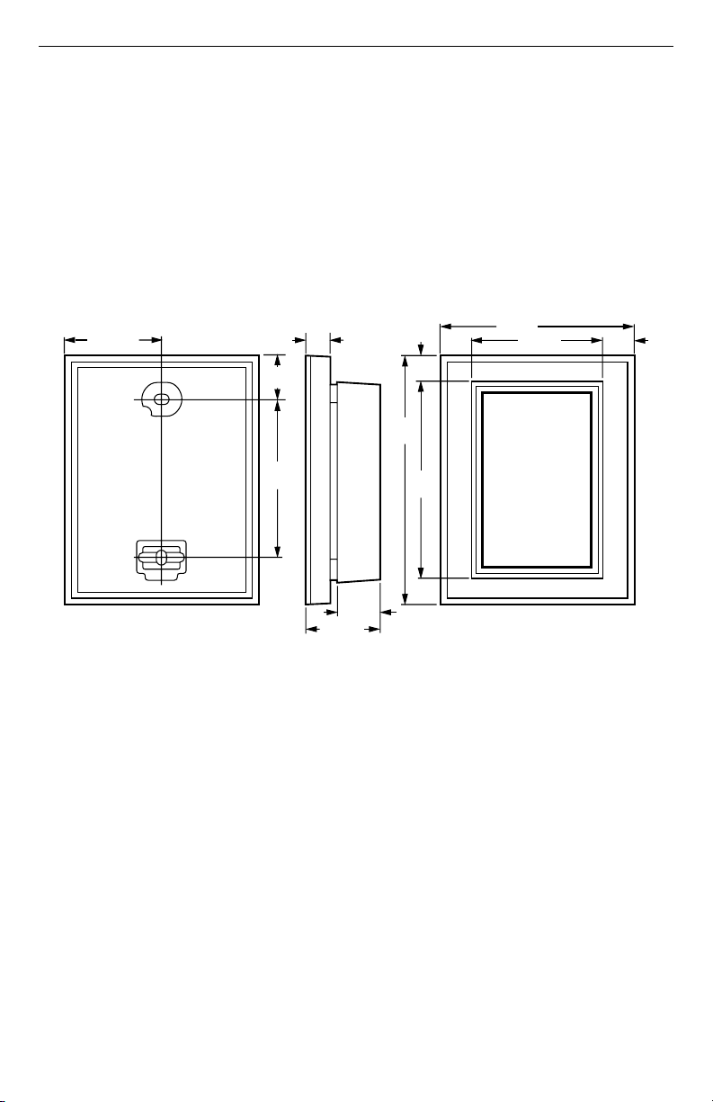
Dimensions: See Fig. 1.
Mounting: Mounts on wall or 2 x 4 in. vertical outlet box
with screws provided.
Temperature Sensor: Thermistor-resistor element.
Cover Thermometer (available on most models):
Element: Bimetal.
Range: 55 to 95°F (13 to 35°C).
® U.S. Registered Trademark
Copyright © 2001 Honeywell • All Rights Reserved
62- 0179
Page 2
T7047C,G,H REMOTE SPACE SENSORS
Setpoint Adjustment (T7047C,G only): Remote
setpoint device such as S963B, T7067B, T7080B.
Sensor Resistance:
For the following negative temperature coefficient (NTC)
devices, resistance decreases as temperature
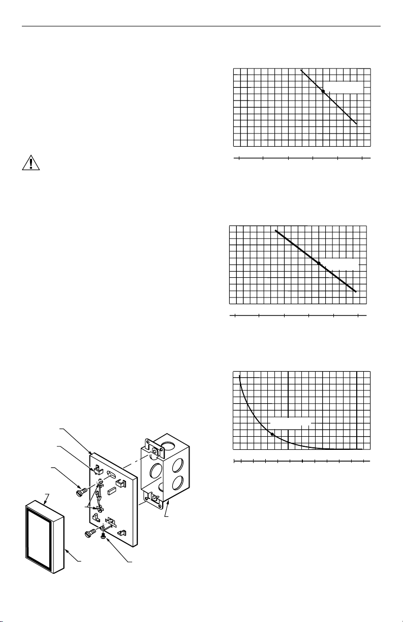
increases (see Fig. 3 through 6):
T7047C1009: 1695 ohms nominal at 75°F (24°C);
resistance changes 21 ohms for each 1°F (0.6°C)
temperature change.
T7047C1025: 1420 ohms nominal at 75°F (24°C);
resistance changes 15 ohms for each 1°F (0.6°C)
temperature change.
T7047C1082: 22,800 ohms nominal at 77°F (25°C);
resistance changes nominally 800 ohms for each
1°F (0.6°C) temperature change at typical ambient
room temperature.
5/8
(16)
3-9/32
(84)
(10)
3/8
1-13/16 (46)
T7047G: 710 ohms nominal at 75°F (24°C);
resistance changes 7.5 ohms for each 1°F (0.6°C)
temperature change.
For the following positive temperature coefficient (PTC)
device, resistance increases as temperature
increases (see Fig. 7):
T7047H: 1093 ohms nominal at 75°F (24°C);
resistance changes 2 ohms for each 1°F (0.6°C)
temperature change.
Accessories:
T7047C1009: 360 ohm S963B1003 Remote Setpoint
Potentiometer.
T7047C1025: 480 ohm S963B1037 Remote Setpoint
Potentiometer, T7067B Single Zone System
Tran smi tter.
T7047C1082: T7080B Multizone System Transmitter.
3-5/8 (93)
4-5/8
(118)
7/16
(11)
3 -3/4
(96)
2-7/16 (62)
19/32
(15)
13/16 (21)
1-5/16 (33)
Fig. 1. T7047 dimensions in in. (mm).
62-0179 2
M17995
Page 3
INSTALLATION
M
T
C
M
S
W
2
9
C
F
2
1
1
1
1
1
R
(
C
F
8
F
C
T7047C,G,H REMOTE SPACE SENSORS
When Installing this Product...
1. Read these instructions carefully. Failure to follow
them could damage the product or cause a
hazardous condition.
2. Check the ratings given in the instructions and on
the product to make sure the product is suitable for
your application.
3. Installer must be a trained, experienced service
technician.
4. After installation is complete, check out product
operation as provided in these instructions.
CAUTION
Electrical Shock or Equipment Damage
Hazard.
Can shock individuals or short equipment
circuitry.
Disconnect power supply before installation.
Location
Locate the remote sensor about 5 ft (1.5m) above the
floor on an inside wall where it will be affected by freely
circulating air at average room temperatures.
Mounting
1. Loosen the cover locking screw with the Allen
wrench provided and remove the device cover.
2. Run wire to the selected location.
3. Thread wire through the semicircular hole in the
device.
4. Make connections to the T7047 (see the Wiring
section).
5. Select the proper screws for the application. Four
mounting screws are provided:
a. Two self-tapping type for wall mounting.
b. Two for outlet box mounting.
6. If air drafts occur through the wall opening,
eliminate with suitable material.
7. Fasten the T7047 on the wall or outlet box with
screws through the mounting holes in the device.
(See Fig. 2.)
8. Replace the cover and tighten the cover locking
screw.
THERMOSTAT
MOUNTING
TAB SLOT (2)
OUNTING
CREW (2)
OUNTING
AB (2 INSIDE
OVER)
WIRING
TERMINALS
COVER
Fig. 2. Mounting the T7047.
COVER LOCKING SCRE
2000
1800
1600
1400
1200
1000
RESISTANCE (OHMS)
10
30 40 50
20
0 10
-10
Fig. 3. T7047C1009 Remote Sensor resistance
change with change in temperature.
ESISTANCE
OHMS)
000
800
600
400
200
000
10
20
-10
Fig. 4. T7047C1025 Remote Sensor resistance
change with change in temperature.
120K
100K
80K
60K
40K
RESISTANCE (OHMS)
20K
20
0 10 20 30 40
-7 50 60 70 80 90 100
Fig. 5. T7047C1082 Remote Sensor resistance
change with change in temperature.
OUTLET
BOX
M2007
3 62-0179
TEMPERATURE (DEGREES)
30 40 50
0 10
TEMPERATURE (DEGREES)
22,800 OHMS AT
77 F (25 C)
60 80 100
40
TEMPERATURE (DEGREES)
60
1695 OHMS AT
75°F (24°C)
70 80 90
60
20 30 40
1420 OHMS AT
75 F (24 C)
70 80 90
20 30 40
140 160 180
120
100
100
200
°
°
M339
M4034
220
M339
Page 4

T7047C,G,H REMOTE SPACE SENSORS
1
9
8
7
6
5
R
(
C
F
R
(
1
F
C
0
3
R
Y
6
8
9
ESISTANCE
OHMS)
000
00
00
00
00
00
10
30 40 50
20
0 10
-10
Fig. 6. T7047G1000 Remote Sensor resistance
change with change in temperature.
ESISTANCE
OHMS)
400
1317
1231
1145
1059
973
20 40
-7010
Fig. 7. T7047H1008 Remote Sensor resistance
change with change in temperature.
TEMPERATURE (DEGREES)
1093 OHMS AT
75 F (24 C)
60
80 100 120
40 506070 80 90
20 30
TEMPERATURE (DEGREES)
710 OHMS AT
75 F (24 C)
70 80 90
60
20 30 40
180 200 220
140 160
Wiring
IMPORTANT
All wiring must agree with applicable codes,
ordinances and regulations.
Fig. 8 through 16 show schematics and typical
connections. Also refer to instructions supplied with other
system components.
IMPORTANT
To avoid electrical interference, which can
cause erratic performance, keep wiring runs as
short as possible and do not run wires adjacent
to the line voltage electrical distribution
systems. Use shielded cable (Belden type 8762
or equivalent for 2-wire and Belden type 8772 or
equivalent for 3-wire). The cable shield must be
grounded only at the controlled equipment
case.
62-0179 4
S963B1003
REMOTE SETPOINT
POTENTIOMETER
B
W
R
T
T
T7047G1000
A1
M7044 OR
M7045 MOTOR
4
T1
1
T2
T1
W960 OR
W927 PANEL
T1
T2
M338
TT
M341
COMMON
M1001
TO 24V
POWE
SUPPL
M338
T7047C
t
110
100
M5354
Fig. 9. T7047C1025 connected to W960 or W927
panel with internal setpoint adjustment.
100
M1002
Fig. 10. Two T7047C1025 Sensors and one
Fig. 11. Typical wiring for T7047H1008 to
T
T
Fig. 8. Internal schematic and typical
wiring for T7047C1009.
T7047C
t
Q7300
TT
T7047C
TT
T7047C
TT
T7047G1000 Sensor providing a
temperature-averaging network for a
T7300/Q7300 Thermostat/Subbase.
EXCEL 500/100/80
CONTROLLER
A1
T7047H
Excel 80/100/500/600 Controller.
Page 5

C7046A
)
0
1
T
9
DISCHARGE
AIR SENSOR
W973 LOGIC PANEL
SENSOR
STAT 24 VAC
C +20 H N
TT13 4 2 51TRTRWB YR
ECONO
T7047C,G,H REMOTE SPACE SENSORS
Q7300
TT
7047G1000
T
T7047G1000
T
T7047C
REMOTE
SENSOR
T
T
POWER SUPPLY. PROVIDE DISCONNECT MEANS AND OVERLOAD
1
PROTECTION AS REQUIRED.
TERMINAL 8 IS USED WITH THE W974A, B ONLY. TERMINAL 6 IS
2
USED WITH THE W974A, B AND/OR REMOTE SENSING ELEMENT
(T7067B ONLY).
3
TERMINALS 6 AND 7 ARE USED TO CONNECT THE REMOTE SENSING
ELEMENT TO THE T7067B ONLY. NO SCREW IS PROVIDED WITH THE
T7067A FOR TERMINAL 7. DOTTED LINES SHOW REMOTE SENSING
ELEMENT CONNECTIONS.
Fig. 12. T7047C1025 used as a remote
sensor with T7067B Thermostat.
Q7300
TT
T7047C
TT
T7067 WALLPLATE
7
6
5
4
T7047C
TT
3
2
2
1
2
L1
(HOT
L2
3
8
M3411
T
1
Fig. 14. Two T7047G1000 Sensors providing a
temperature-averaging network for a
T7300/Q7300 Thermostat/Subbase.
Q7300
TT
T7047G
T
T7047G
T
Fig. 15. Five T7047G1000 Sensors providing
a temperature-averaging network for a
T7300/Q7300 Thermostat/Subbase.
T7047C
TT
T
T
T7047G
T
T7047G
T
Q7300
TT
T7047C
TT
T
T
T7047G
T
T7047C
M342
T
T
M3422
TT
T7047C
TT
Fig. 13. Four T7047C1025 Sensors providing
a temperature-averaging network for a
T7300/Q7300 Thermostat/Subbase.
T7047C
TT
M342
T7047C
TT
T7047C
TT
Fig. 16. Nine T7047C1025 Sensors providing
a temperature-averaging network for a
T7300/Q7300 Thermostat/Subbase.
5 62-0179
T7047C
TT
T7047C
TT
T7047C
TT
T7047C
TT
M341
Page 6

T7047C,G,H REMOTE SPACE SENSORS
W7080A
LOAD ANALYZER
C3 H3
1. THE W7080 REQUIRES SEPARATE TRANSFORMER.
DO NOT GROUND SECONDARY.
2. EACH M744, M745 MOTOR REQUIRES SEPARATE
TRANSFORMER. DO NOT GROUND SECONDARY.
C2
H2
C1
CHI LO HT
12345
ZONE 1
DAMPER
MOTOR
M734J
R
C
T7047C1082
(USED WITH
T7080B ONLY)
T
T
POWER SUPPLY. PROVIDE DISCONNECT MEANS AND OVERLOAD
1
PROTECTION AS REQUIRED.
2
TERMINALS 3, 7 AND 8 ARE ALL EQUIVALENT COMMON TERMINALS.
3
RESISTOR AND TIME SWITCH IN SERIES BETWEEN TERMINALS 5-7.
SEE FIG. 6, PAGE 5.
Fig. 17. T7047C1082 used as a remote
6
24 VAC
NIGHT
SETBACK
RESISTANCE
3
sensor with T7080B Thermostat.
ZONES
1
H1
7891011
24 VDC
+
–
COMMON
L2
L1
(HOT)
T7080 FOR ZONE 1
7
2
6
5
4
12
1
2
3
8
2
C7100B
DISCHARGE
AIR
SENSOR
M5355
62-0179 6
Page 7

OPERATION AND CHECKOUT
T7047C,G,H REMOTE SPACE SENSORS
Operation
The T7047C,G Remote Sensor control element is a
negative temperature coefficient (NTC) thermistor. As
the room temperature increases, the resistance of the
thermistor decreases.
The T7047H Remote Sensor control element is a
positive temperature coefficient (PTC) thermistor. As
the room temperature increases, the resistance of the
thermistor increases.
The change in the thermistor resistance causes the
motor, system logic panel, or system transmitter bridge
circuit to become unbalanced. As the electronic motor,
system logic panel or system transmitter circuits react to
rebalance the circuit, damper or valve movement, or
sequential staging of heating and/or cooling equipment
occurs.
Low Range Thermostat
Use caution when setting temperatures below 40°F
(5°C). A low temperature setpoint can result in
temperatures below freezing in areas distant from the
remote sensor.
Calibration
The T7047 Remote Space Sensor is accurately
calibrated at the factory. It cannot be field calibrated.
Checkout
Allow the T7047 Remote Space Sensor to stabilize to
ambient conditions before taking a resistance
measurement. Measure nominal resistance according
to the values described in the Specifications section.
Measure the sensor resistance in accordance with the
temperature curves. See Fig. 3 through 7.
Check operation of the complete control systems as
directed in the associated technical publications.
7 62-0179
Page 8

Home and Building Control Home and Building Control
Honeywell Honeywell Limited-Honeywell Limitée
1985 Douglas Drive North 35 Dynamic Drive
Golden Valley, MN 55422 Scarborough, Ontario
M1V 4Z9
62-0179 B.B. 9-01 www.honeywell.com/building/components
Printed in U.S.A. on recycled
paper containing at least 10%
post-consumer paper fibers.
 Loading...