

Page 1
APPLICATION:
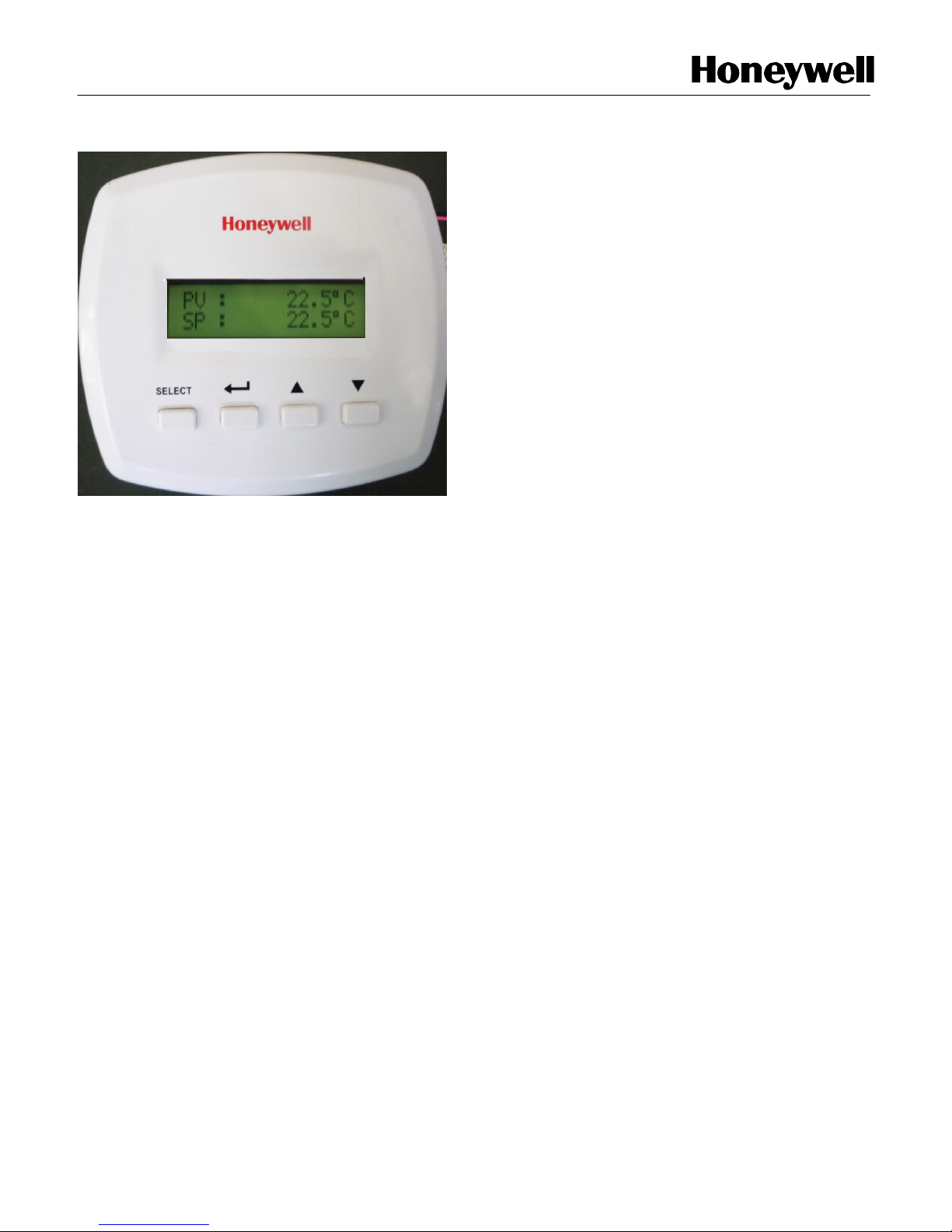
This standalone micro-controller based LCD temperature
controller provides proportional plus integral (P+I) and on/off
temperature control for commercial Heating, Ventilating & Air
Conditioning System such as Hydronic Heating, Air Handling
Unit, Heat Exchanger or Condensing Tower.
This controller has a modulating analog 2 to 10Vdc or 4 to
20mA output and a 2A on/off output to realize various optional
control functions including cool/heat changeover, heat/cool
sequence control, emergency interlocking and auto-alarming
control.
Table of Contents
Application………………………………………….1
Features…………………………………………….1
Specification………………………………………..2
Dimensions, Installation & Wiring Terminals..….3
Control Operation………………………………….4
Installer SetUp……………………………………..12
FEATURES:
• PI (proportional plus integral) control action
provides accurate, stable and comfortable
temperature control.
• Compatible with series 70 direct-coupled
damper / valve actuator like ML7161,
ML7174, ML7420 / ML7421series ML7425,
ML7984 series, N20010, S10010, M7410E
series, CN7505, CN7510 / CN72 series
CN7220 & CN7234 also VC79 series etc.
• Backlit LCD to display both setting and
measured value.
• Adjustable Zero Energy Band, On/Off
Differential, Proportional Band and
Temperature Offset.
• Analog output can be forced manually to be
convenient for installation & commissioning.
• Optional 2 to 10Vdc or 4 to 20mA direct
acting and reverse acting analog output.
• Selectable internal and external temperature
sensor.
• Wide temperature control range (-20 to 110
°C by using external temperature sensor) is
suitable for extreme temperature control such
as steam and ice water.
• Watch Dog Timer: to resume the controller
from hanging condition.
• Brownout effect to avoid malfunctioning and
care on power ON and power OFF.
• Pluggable terminal block allows pre-wiring
outside of the controller.
• Compact size and slim design provide
elegant and attractive modern style
appearance.
Page 1 of 18 APHITEMPCON001-11-04
Page 2

SPECIFICATIONS:
IMPORTANT: The specifications given in this publication
do not include normal manufacturing tolerances.
Therefore, this unit may not exactly match the listed
specifications. Also, this product is tested and calibrated
under closely controlled conditions and some minor
difference in performance can be expected if those
conditions are changed.
MODEL: T2798I2000
Control Performance: This controller provides 4 to 20mA
or 2 to 10Vdc Proportional plus Integral modulating control
and 4(2) A On/Off control.
INPUTS:
1) Analog - 1 No. (Only PT1000)
2) Digital - 1 No. (Dry Contact)
OUTPUTS:
1) Analog - 1 No.
2) Digital - 1 No.
SETPOINT RANGE:
5-50°C (internal temperature sensor)
-20-110°C (external temperature sensor)
POWER SUPPLY: AC24V ±20%, 50/60Hz,
2 VA.
ANALOG OUTPUT:
2 to 10Vdc OR
4 to 20mA.
DIGITAL OUTPUT:
2A, 24Vac
MOUNTING: Direct wall mounting
with standard electrical mounting box [type-3 module].
TERMINALS: Plug-in screw terminals
are suitable for 1.5 square mm wire.
OPERATING AMBIENT:
0-50°C, 5-80%RH.
Shipping & Storage:
-20 - 45°C, 5-95%RH
ACCURACY:
< / = +/- 0.30°C
REMOTE SENSOR: RTD
PT1000.
Maximum 15m cable length
(line resistance < 4.5Ω)
Enclosure: ABS Plastic, 2-piece. (IP30)
OPERATING PARAMETER:
See TABLE 2 for installer selections.
Parameter Selection
Zero Energy Band 1.5 or 3.0°C
On/Off Differential 0.5 to 3.0°C (0.5°C
step change)
Proportional Band 2.0 to 19.0°C (0.1°C
step change)
Offset -3.0 to 3.0°C (0.5°C
step change)
Set Point Definition Heating, Cooling,
H/C midpoint,
Heating/Alarming or
Cooling/Alarming.
Main Sensor Remote or Internal
ACCESSORIES:
Duct Mount Remote Sensor PT1000.
DIN Class B.
Model # RSPT1000
Probe Length: 300mm
(to be ordered separately)
Page 2 of 18 APHITEMPCON001-11-04
Page 3
1234567
8
14
135
17
135
107.5
83.5
86.5
20
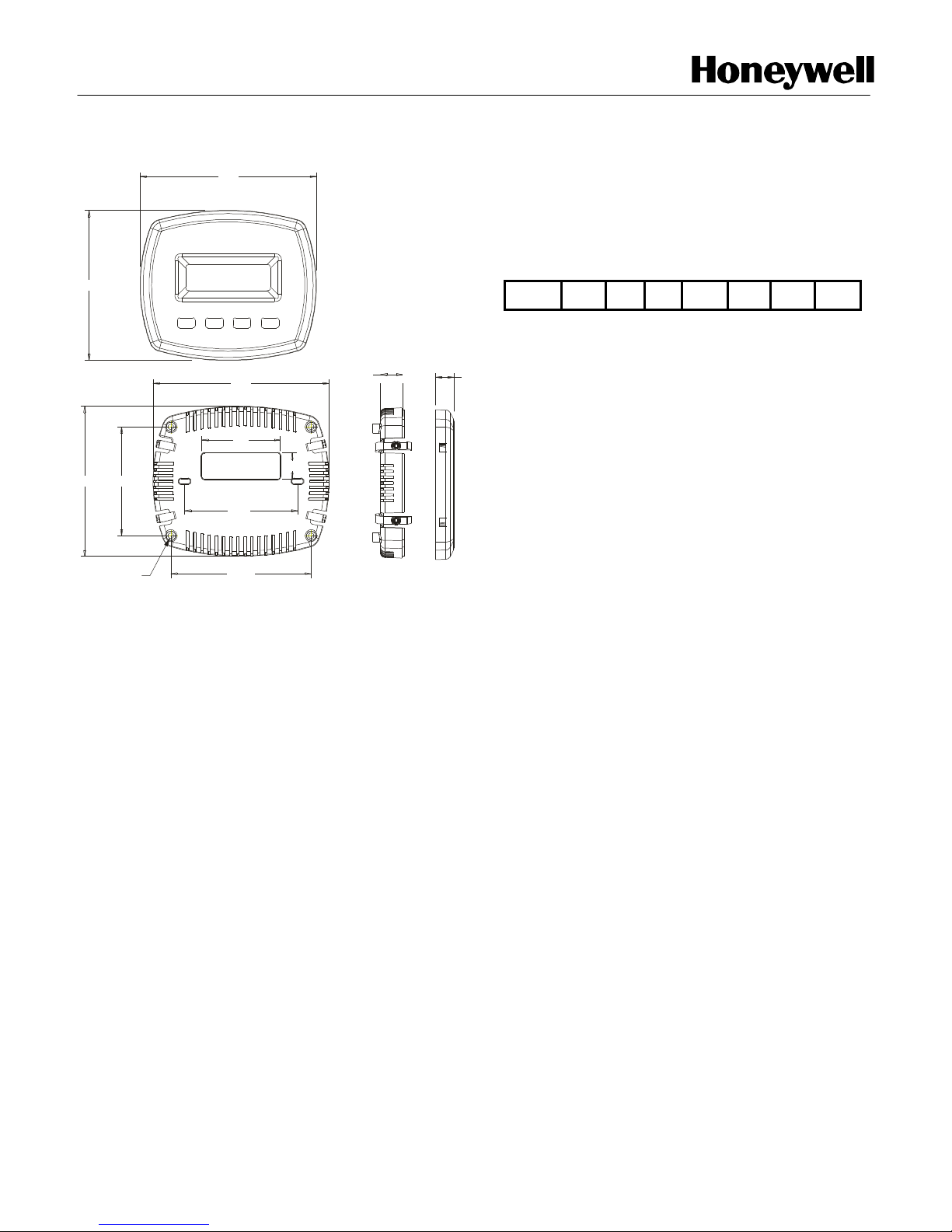
DIMENSIONS:
115
60
115
M3 Self Tapping screw
INSTALLATION:
The controller can be installed in any position on a
flat surface using electrical box [Type-3 Module].
To measure room temperature by internal sensor
and choosing wall mounting method, it is
recommended to be installed 1.5m (about 5 ft.)
above the floor in the area at average temperature
conditions.
For all kinds of mounting method, the product must
be installed in an area with good air circulation.
Do not install the controller where it may be
affected by:
Draughts or dead air spots behind doors
and in corners.
Hot or cold air from ducts.
Radiant heat from sun or appliances.
Concealed pipes and chimneys
WIRING TERMINAL:
1 & 2 – Relay Output
3 – 0Vac
4 – 24Vac
5 – Digital Input
6 – 2…10Vdc OR 4…20mA analog output
7 & 8 – PT1000 Remote Sensor
Page 3 of 18 APHITEMPCON001-11-04
Page 4

CONTROL OPERATION:
Input1 –Remote Temperature Sensor
The controller has an integral sensing device mounted internally. It is also possible to install a
remote room or duct return sensor at different locations. See wiring diagram.
Note#1: The remote sensor should be PT1000 (Refer Accessories)
Input2- Emergency Input
Input2 is to connect with an On/Off dry contact for system error or emergency interlock control. If
the contact is close, the controller will automatically close all output (or open to the maximum
position in reverse mode) and cut off the power. The controller can only be restarted manually.
Note#2: If you don’t want to use the interlock function/emergency input please use a jumper wire
to connect input2 (terminal no.5) and neutral port (Terminal no.3), see wiring diagram.
Output1-Modulating Analog Output (2 to 10Vdc or 4 to 20mA)
Output1 is modulating P+I analog 2 to 10Vdc or 4 to 20mA. It can be selected by Selector
switch. The output signal is normal mode (2 to 10Vdc or 4 to 20mA) or reverse mode (10 to
2Vdc or 20 to 4mA) selectable.
Output2- On/Off digital Output (2A, 24Vac)
Output2 is digital output with 24VAC 2A Contact rating, nominal capacity. It provides On/Off
control for electric heater, on/off valve actuator or fan etc.
Output2 can provide limitation control through pre-setting a separate temperature limitation.
Page 4 of 18 APHITEMPCON001-11-04
Page 5
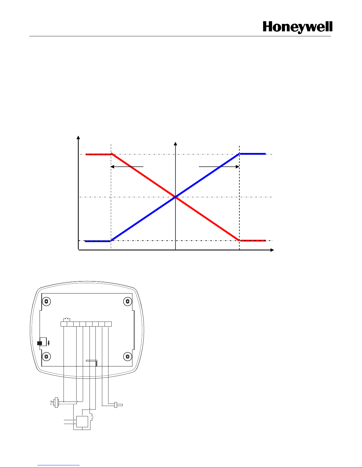
Heat / Cool Changeover of Output1
Valve Open
Temperature Increase
Valve Close
Output1 is suitable for Heat/Cool changeover (manually) control in 2pipe AHU, Zoning control or
Hydronic Heating application. Wiring connection is shown in fig.
With cooling or heating selected, the user set point (SP) will be positioned at the middle of
proportional band. The output percentage is proportional to the temperature measured and
decided by proportional band. The proportional band can be set from 2.0°C to 19.0°C. The
control logic is seen in Diagram 1.
Diagram 1:
100%
50%
0%
Wiring Diagram
Heating
sp
Cooling
Proportional band
Pt1000
sensor
24VAC
A/OD/I
8
PT1000
REMOTE SENSOR
4 - 20 mA
2 - 10 VDC
110VAC /
230VAC
1 2 3 4 5 6 7
L
24VAC
N
0VAC
E
POWER
SUPPLY
0VAC
2-10VDC /
4-20mA
Actuator
Unit
Add link between terminal No 5 & 3.
Page 5 of 18 APHITEMPCON001-11-04
Note: If Emergency IP [D/I] not used then
Page 6
Heating + Cooling Sequence control with Zero Energy Band
Z-Band
Output 2
Valve Open
Temperature Increase
Valve Close
Output 1
This kind of control requires Zero Energy Band (Z-Band). Z-Band is pre-set. For control purpose,
the zero energy band is centered on the user set point (SP), so its value defines the effective
heating (H SP) & cooling (C SP) set points. The cooling set point (C SP) will be positioned on
the right side of Z-Band & the heating set point (H SP) on the left side of Z-Band. Z-Band can be
set as 1.5°C or 3.0°C. Any change of set point will cause both heating and cooling set points to
change in parallel. Either output1 or output2 can be used for cooling or heating control. The
control logic is seen in Diagram 2 and 3.
Diagram 2: Heating + Cooling Sequence Control.
100%
0%
50%
Heating
H SP
SP
C SP
Cooling
Diff
Page 6 of 18 APHITEMPCON001-11-04
Page 7

Diagram 3: Cooling + Heating Sequence Control.
Z-Band
Output 1
Valve Open
Valve Close
SP
Output 2
H SP
Heating
100%
Diff
50%
0%
C SP
Cooling
Page 7 of 18 APHITEMPCON001-11-04
Page 8

Output 1
Valve Open
Temperature Increase
Valve Close
Output 2
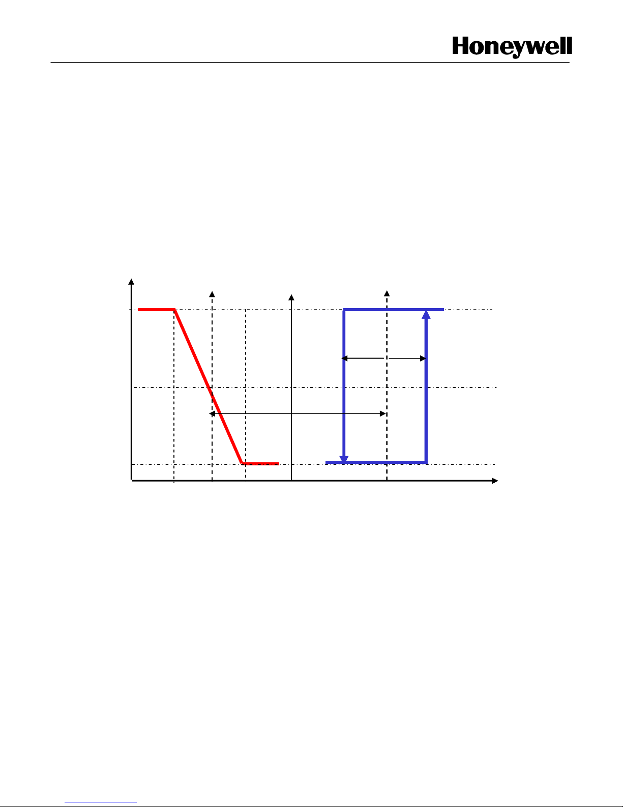
Heating/Cooling + Temperature Limitation Control
Output2 can be used for temperature limitation control. To select this function, 2 temperature set
points must be pre-set. One is in the mid of proportional band of output1 (C SP / H SP) as main
setting temperature. The second one is the temperature limitation of heating or cooling (A SP).
In this mode if the measured temperature is higher (in heating mode) or lower (in cooling mode)
than temperature limitation, output2 will close and output an alarming signal. The control logic is
seen in Diagram 4 and 5.
Diagram 4: Cooling + Temperature Limit Control.
A SP
Alarm
100%
50%
0%
C SP
Cooling
Page 8 of 18 APHITEMPCON001-11-04
Page 9

Output 2
Valve O
pen
Temperature Increase
Valve Close
Output 1
Diagram 5: Heating + Temperature Limit Control.
H SP
Heating
100%
50%
0%
Wiring Diagram
I] STANDARD WIRING DIAGRAM:
A SP
Alarm
Pt1000
A/OD/I
sensor
ON / OFF
Valve /
Actuator
8
PT1000
REMOTE SENSOR
4 - 20 mA
2 - 10 VDC
110VAC /
230VAC
L
N
E
POWER
SUPPLY
0VAC
24VAC
1 2 3 4 5 6 7
24VAC
0VAC
2-10VDC /
4-20mA
Actuator
Unit
Note : If Emergency IP [D/I] not used then add link between terminal No 5 & 3.
Page 9 of 18 APHITEMPCON001-11-04
Page 10

A]
WIRING DIAGRAM T2798I2000 WITH ML-7984
A
/
O
D
/
I
DIP SWITCH CONFIGURATION
B]
WIRING DIAGRAM T2798I2000 WITH ML-7421
230VAC, 50Hz
0-10V / 0- 20mA
2-10V / 4- 20mA
II] T2798I2000 wiring with frequently used Actuators
4 - 20 mA
2 - 10 VDC
50 / 60 Hz
OVAC
110VAC
230VAC
NOTE:
DIRECT ACTING FUN CTION (A CTUATOR STEM MOVES
UPWARD WITH S IGNAL INCREASES) OR REVE RSAL ACTING
FUNCTION (ACTUATOR STEM MOVES DOWN WARDS WITH
SIGNAL INCREAS ES)
50 / 60 Hz
OVAC
110VAC
230VAC
TRANSFORMER
4 - 20 mA
2 - 10 VDC
TRANSFORMER
24VAC
0VAC
24VAC
0VAC
0VAC
A/O
D/I
24VAC
1 2 3 4 5 6 7 8
Pt1000
sensor
Pt1000
0VAC
24VAC
sensor
NTC20K
Ml7984
R
T6
W
C
PT1000
REMOTE
SENSOR
24VAC
T5
FUNCTION
2-10V DC DIRECT ACTING
10-2V DC REVERSE ACTING
%
100 50 0
0 0 0
REMOTE
SENSOR
TRANSFORM ER
230V AC, 50Hz
DIP SWITCH OF ML 7984A
ML-7421
M
W1
W2
V
mA
ML-7421
TRANSFORMER
24VAC
ON
OFF
ON
OFF
W2
10V / 20mA
W3
10V / 20mA
Page 10 of 18 APHITEMPCON001-11-04
Page 11

1 2 3 4 5
CN-7510
To IMS
optional
D]
WIRING DIAGRAM T2798I2000 WITH
OD/I
C]
WIRING DIAGRAM T2798I2000 WITH M7410E
A
/
O
D
/
I
SELECT 2-1 0V OPTION FO R
USING M7 410E with T2798I 2000
50 / 60 Hz
OVAC
110VAC
230VAC
4 - 20 mA
2 - 10 V DC
TRANSFORMER
50 / 60 Hz
OVAC
110VAC
230VAC
Pt1000
0VAC
24VAC
sensor
24VAC
0VAC
N10010/N20010/N34010/CN7510
4 - 20 mA
2 - 10 VDC
TRANSFORMER
24VAC
0VAC
0VAC
24VAC
PT1000
REMOTE
SENSOR
Pt1000
A/
sensor
0 - 100%
100 - 0%
GREEN
BROWN
WHITE
PT1000
REMOTE
SENSOR
M7410E
0 - 100%
100 - 0%
0 - 10V
2 - 10V
HOT
0 - 10V
2 - 10V
INPUT
FEEDBACK
COM
Page 11 of 18 APHITEMPCON001-11-04
Page 12

4 - 20 mA
E]
WIRING DIAGRAM T2798I2000 WITH VC-7934
Pt1000
A/O
0VAC
D/I
24VAC
sensor
VC-7934
50 / 60 Hz
OVAC
110VAC
230VAC
2 - 10 VDC
PT1000
REMOTE
SENSOR
TRANSFORMER
24VAC
0VAC
BLACK
BROWN
BLUE
HOT
COM
1 2 3
INPUT
Installer Set-Up:
1. Power ON/OFF :
- Connect the main power. Display will show “Honeywell”, as shown in fig.1, for 5 Sec.
Then display will show the Process value
(PV) and Set point (SP) as shown in fig.2
H o n e y w e l l
Fig. 1
2. Set Point configuration (SP):
- Press key one time to step up the set point value by 0.1°C. If pressed
continuously for more than ten steps then the value will increment by the step of 1.0°C
up to 60.0°C (for internal sensor) or 110.0°C (for external sensor). Release key to
stop the increment of temp set value.
- Press key one time to step down set point value by 0.1°C. If pressed
continuously for more than ten steps then the value will decrement by the step of 1.0°C
up to 10.0°C (for internal sensor) or –20.0°C (for external sensor). Release
key to stop decrement of temp set value.
- Press “ENTER” key to save the set value.
P V : 3 0 . 2 ° C
S P : 1 9 . 0 ° C
Fig. 2
Page 12 of 18 APHITEMPCON001-11-04
Page 13

3. Zero Energy Band setting:
- Press “SELECT” to choose “Zero Energy Band Setting”, the display will show as in
fig.3
- Press key one time to switches from 1.5°C to 3.0°C.
- Press key one time to switches from 3.0°C to 1.5°C.
- Press “ENTER” key to save the set value.
P V : 3 0 . 2 ° C
Z - B A N D 3 . 0 ° C
Fig. 3
4. Differential setting:
- Press “SELECT” to choose “Differential Setting”, the display will show as in fig.4
- Press key one time to step up the differential setting by 0.5°C, it will stop
incrementing at 3.0°C. The range is 0.5 to 3.0 °C.
- Press key one time to step down the differential setting by 0.5°C. It will stop
decrementing at 0.5°C. The range is 3.0 to 0.5 °C.
- Press “ENTER” key to save the setting value.
P V : 3 0 . 2 ° C
D I F F 1 . 0 ° C
Fig. 4
5. Proportional Band Setting:
- Press “SELECT” to choose “Proportion Band
Setting”, the display will show as in fig.5
- Press key one time to step up the Proportional band by 0.1°C. If pressed
continuously for more than ten steps then the value will increment by the step of 1.0°C
up to 19.0°C. Release
key to stop the increment of the value.
- Press key one time to step down Proportional Band by 0.1°C If pressed
continuously for more than ten steps then the value will decrement by the step of 1.0°C
up to 2.0°C. Release key to stop the decrement of the value.
- Press “ENTER” key to save the setting value.
P V : 3 0 . 2 ° C
P - B A N D 1 0 . 0 ° C
Fig. 5
6. Offset Setting:
- Press “SELECT” to choose “Offset Setting”, the display will show as in fig.6
- Press key one time to step up Offset by 0.1°C. If pressed continuously for
more than ten steps then the value will increment by the step of 1.0°C up to 3.0°C.
Release key to stop increment of the value. The range is –3.0 to 3.0 °C.
- Press key one time to step down Offset by 0.1°C. If
pressed continuously for more than ten steps then
the value will decrement by the step of 1.0°C up to -3.0°C. Release
key to stop increment of the value.
Page 13 of 18 APHITEMPCON001-11-04
Page 14

The range is 3.0 to –3.0 °C.
- Press “ENTER” key to save the setting value.
P V : 3 0 . 2 ° C
O F F S E T - 1 . 0 ° C
Fig. 6
7. Mode Setting:
- Press “SELECT” to choose “MODE Setting”, the display will show as in fig.7
- Press key one time to step up. The total number of modes is 6. It will stop
incrementing at last mode i.e. H/AL mode.
-
MODES: Output 1 function: Output 2 function:
COOL Cooling No Function
HEAT Heating No Function
C/H Cooling Heating
H/C Heating Cooling
C/AL Cooling Low Temp. limit Alarm
H/AL Heating High Temp. limit Alarm
- Press key one time to step down. The total number of modes is 6. It will stop
decrementing at first mode i.e. COOL mode.
- Press “ENTER” key to save the setting value.
-
P V : 3 0 . 2 ° C
M O D E C O O L
Fig. 7
8. Sensor setting :
- Press “SELECT” to choose “Sensor Setting”, the display will show as in fig. 3
- Press key one time to switches from INT to EXT.
INT : Internal sensor
EXT : External sensor
- Press key one time to switches from EXT to INT.
- Press “ENTER” key to save the setting value.
P V : 3 0 . 2 ° C
S E N S O R I N T
Fig. 8
Page 14 of 18 APHITEMPCON001-11-04
Page 15

9. Reverse Action Setting :
- Press “SELECT” to choose “Reverse Setting”, the display will show as in fig. 9
- Press key one time to switches from OFF to ON.
OFF : Output1 in normal mode, i.e. 2 - 10Vdc or 4 - 20mA
ON : Output in reversing mode, i.e. 10 - 2Vdc or 20 - 4mA.
- Press key one time to switches from ON to OFF.
- Press “ENTER” key to save the setting value.
P V : 3 0 . 2 ° C
R E V E R S E O F F
Fig. 9
10. Display Setting :
- Press “SELECT” to choose “Display Setting”, the display will show as in fig.10
- Press key one time to switches from OFF to ON.
OFF : Normal mode, as shown in fig. 2.
ON : Percentage mode, output1 is percent value (2Vdc or 4mA – 0% & 10Vdc
or 20mA – 100%) as shown fig.11.
- Press key one time to switches from ON to OFF.
- Press “ENTER” key to save the setting value.
P V : 3 0 . 2 ° C
D I S P L A Y O F F
Fig. 10
P V : 3 0 . 2 ° C
A 0 : 9 1 %
Fig. 11
11. Manual Setting:
- Press “SELECT” to choose “Manual Setting”, the display will show as in fig.12
- Press key one time to switches from OFF to ON.
OFF: Manual OFF
ON : Manual ON
- Press key one time to switches from ON to OFF.
- Press “ENTER” key to save the setting value.
- If manual on, the display will show as in fig.13
P V : 3 0 . 2 ° C
M A N U A L O N
Fig. 12
P V : 3 0 . 2 ° C
A 0 : 9 1 %
Fig. 13
Page 15 of 18 APHITEMPCON001-11-04
Page 16

- If manual ON, press key one time to step up the display value by 1%. If
pressed continuously for more than ten steps then the value will increment by the step
of 1.0% up to 100%. Release key to stop the increment of value.
- If manual ON, press key one time to step down the display value by 1%.
- If press continuously more than ten steps then the value will decrement by the
step of 1.0% up to 0%. Release key to stop the decrement of value.
- After 90 minutes of manual ON operation the controller will return to manual OFF
mode automatically.
12. F1 Setting :
- Press “SELECT” to choose “F1 setting”, the display will show as in fig.14
- Press key one time to step up the Integral time by 0.1Sec. If pressed
continuously for more than ten steps then the value will increment by the step of
1.0Sec. up to 60.Sec. Release
key to stop the increment of value.
The range is 0.1 to 60-Sec.
- Press key one time to step down the Integral time by 0.1Sec. If pressed
continuously for more than ten steps then the value will decrement by the step of
1.0Sec. up to 0.1Sec. Release key to stop the decrement of value. The range is 60
to 0.1Sec.
- Press “ENTER” key to save the setting value.
- This value setting shows how long the output1 will update the output value
P V : 3 0 . 2 ° C
F 1 ( I ) 1 . 0 S E C
Fig. 14
13. F2 Setting :
- Press “SELECT” to choose “F2 setting”, the display will show as in fig.15
- Press key one time to step up the Alarm Set point by 0.1°C. If is pressed
continuously for more than ten steps then the value will increment by the step of 1.0°C
up to 60.0°C (for internal sensor) or 110.0°C (for external sensor). Release key to
stop the increment of value.
- Press key one time to step down the Alarm set point by 0.1°C. If pressed
continuously for more than ten steps then the value will decrement by the step of 1.0°C
up to 10.0°C (for internal sensor) or -20.0°C (for external sensor).
Release key to stop decrement of value.
- Press “ENTER” key to save the setting value.
P V : 3 0 . 2 ° C
F 2 3 0 . 0 ° C
Fig. 15
Page 16 of 18 APHITEMPCON001-11-04
Page 17

Default Setting:
S e t t i n g P a ra m e t e rs D e fa u lt V a lu e
Z - B A N D 1 .5 °C
D IF F 0 .5 °C
P - B A N D 2 .0 °C
O F F S E T 0 °C
C / A L
M O D E
R E V E R S E O F F
D IS P L A Y O F F
M A N U A L O F F
S P 2 1 °C
F 1 ( I) 1 5 S E C
A L A R M (F 2 ) 1 0 °C
( C O O L + A L A R M )
IMPORTANT: Before setting, please check the following points.
1. Inspect the controller visually & check the push button before connecting the main power.
2. There should not be any abnormal phenomena or obvious shipping damage.
3. Check the Selector Switch & make sure that the switch is set at the right position.
Page 17 of 18 APHITEMPCON001-11-04
Page 18

Environmental & Combustion Controls
Honeywell Automation India Limited
56 & 57, Hadapsar Industrial Estate,
Pune – 411 013, India.
Phone: (91) 20 6603 9400
Fax: (91) 20 6603 9979
Subject to change without notice. Printed in India.
Page 18 of 18 APHITEMPCON001-11-04
 Loading...