

Page 1
Thermostatic Control
The T104F Thermostatic Control is used with a V110
Valve Body to control radiators, convectors, baseboard
heating units, or other heating units with standard capacity
requirements. The control is self-powered and requires no
electrical connection. The T100A includes a setpoint dial
and valve actuator, connected by a capillary tube to a sensor.
The T104F Control attaches to the valve body by threaded
connections and may be mounted at any angle. Install the
remote sensor beneath the heating coils in the cold air return, or on a nearby wall where the air flow is not restricted.
The setpoint dial has reference marks (1-6). The control
has a low limit of 43°F (6°C) when the dial is turned fully
clockwise to the frost protection mark*. The red button
indicates the 68°F (20°C) setpoint limit. Higher settings may
be made by holding in the button while turning. The thermostatic sensor is protected by a safety spring against temperatures to 125°F (52°C).
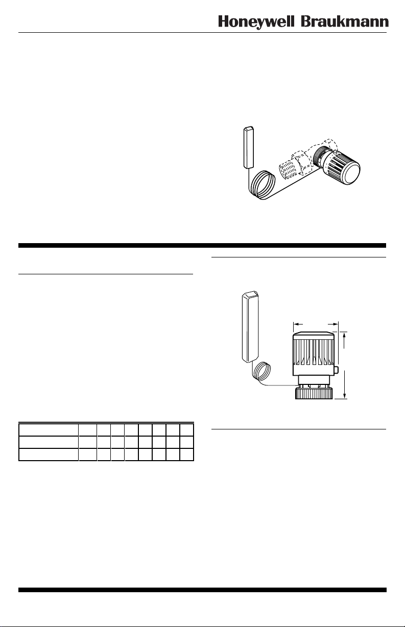
T104F
3
2
M9730
Specifications
MATERIALS OF CONSTRUCTION:
Body: Industrial grade plastics with low thermal
conductivity.
Fastening Ring: Plated brass.
Internal Parts: Brass thermostat capsule, other metals.
TEMPERATURE RANGE: 43° to 79°F (6° to 26 °C).
MAX. SENSOR TEMPERATURE: 125°F (52°C).
MAX. OVERALL DIMENSIONS: 2-1/8 in. (54 mm) wide,
3-5/16 in. (84 mm) long. See Fig. 1.
CAPILLARY LENGTH: 6 ft. 8 in. (2 m).
TEMPERATURE SETTINGS:
These are the setpoint temperatures, which correspond
to the setpoint dial reference marks, under ideal conditions.
Factors affecting the temperature at the sensor vary for each
installation. It may be necessary to adjust the setpoint
higher or lower to obtain the desired space temperature.
Temperature 0 *123456
°F Off 43 46 54 61 68 73 79
°C Off 6 8 12 16 20 23 26
Fig. 1—T104F dimensions in in. (mm).
2 1/8 (54)
M9731
AVAILABLE VALVE BODIES:
See Fig. 2.
3 5/16
(84)
MAX.
1 62-3047
C. H. • 12-94 • ©Honeywell Inc. 1994 • Form Number 62-3047
Page 2
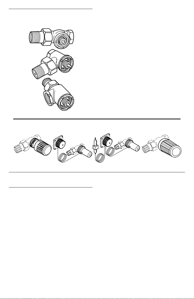
Fig. 2—V110 Valve Bodies.
VALVE BODIES
V110D
V110E
V110F
M9735
Fig. 3—T104A,B,C,V Thermostatic Controls.
4
5
3
3
2
2
1
OTHER AVAILABLE T100 THERMOSTATIC
CONTROLS (See Fig. 3):
T104A Control with internal sensor.
T104B Control with remote sensor/setpoint.
T104C Control with remote sensor and remote setpoint.
T104V Control with internal sensor and tamper-resistant
setpoint and mounting.
ACCESSORY
A104F1007 Limit Pins.
G111B1053 Bulb guard for protection of sensor when
mounted on the wall.
4
5
3
2
1
T104B T104CT104A T104V
Installation
IMPORTANT: The T104F can be mounted inside an enclo-
sure if the sensor is located a minimum of 3 in. (76 mm)
beneath the heating coils in the cold air return. Coil
excess capillary tubing beneath and away from the
62-3047 2
M9736
heating coils. Take care not to break, kink or sharply
bend the capillary tubing.
When mounting the T104F, make sure the bosses on
the T104F base fit securely into the valve body grooves.
Firmly hand tighten the knurled ring. Improper mounting can cause overheating. Refer to Fig. 4 for typical
installations.
Page 3

Fig. 4—Typical installations.
18 INCH
MINIMUM
M9734
Settings and Calibration
The T104F Control includes an adjustable range limit-
ing pin (order additional pins separately). The pin is factory-set to limit the low range of the control to the frost
protection (*) setting (see Fig. 5). The pin can be moved to
a different low or high limit setting and lock point, or it can
be removed. Use a second pin if both low and high limit
settings are desired.
Fig. 5—Temperature settings.
ADJUSTMENT RANGE SETTING
°C
OFF
OFF
°F
01
6
4384612541661206823732679
SCALE MARKING
*
23
Setting the Limit
To set a limit different from the factory setting, proceed
as follows:
1. Determine the desired temperature range limit or locking temperature. Select the appropriate number on the adjustment knob to match the desired temperature setting. See
Fig. 5.
1PIN REQUIRED.
2
FACTORY SETTING.
TEMP.
4
56
2
1
1
PIN
POS.
3
NONE
4a
4b
4b
4b + *
5
5 + *
*
RANGE
°F
43 - 79
61 - 79
OFF - 79
68
72
0 - 68
43 - 68
0 - 73
43 - 73
TEMP.
RANGE
°C
6 - 26
16 - 26
OFF - 26
20
22
0 - 20
6 - 20
0 - 23
6 - 23
M9729
3 62-3047
Page 4

2. Lift the end cap off the adjustment knob. See Fig. 6.
Fig. 6—Lift the end cap off the adjustment knob.
3. Remove the adjustment knob from the actuator as
2
ACTUATOR
ADJUSTMENT
KNOB
END
3
CAP
M9715
follows:
a. Turn the adjustment knob so the desired knob setting
is aligned with the white line on the actuator base.
b. Pull the knob off the head or use a screwdriver inserted
into one of the slots to pry off the knob. See Fig. 7.
Fig. 7—Remove the knob from the actuator.
4. Push the limit pin up and slide it into the slot that
BASE
ACTUATOR HEAD
ARM CLIP (3)
M9714
SCREWDRIVER SLOT (2)
WHITE LINE
CALIBRATION
INDENT
RED
BUTTON
corresponds with the desired temperature limit. If the lower
limit remains at the frost protection mark (*), insert an
additional pin in the slot that corresponds with the second
limit.
Example 1:
If the desired temperature range is 43° to 73°F (6° to
23°C), leave the pin in the slot marked * and add one pin in
slot 5.
Example 2:
If the desired temperature range is OFF to 68°F (23 °C),
move the pin to slot 5. No additional pin is required.
5. To replace the adjustment knob, realign the knob
setting in step 3a with the white line on the base and push the
knob toward the base. Make sure the three arm clips snap into
place at the top of the adjustment knob. If the actuator was
turned with the adjustment knob off, recalibrate the control
according to the instructions in Recalibrate T104F Control
section.
6. Replace the end cap.
Locking the Control at a Single Temperature
1. Determine the desired locking temperature. Select the
appropriate number on the adjustment knob to match the
desired temperature setting. See Fig. 5.
2. Lift the end cap off the adjustment knob. See Fig. 6.
3. Remove the adjustment knob from the actuator as
follows:
a. Turn the adjustment knob so the desired knob setting
is aligned with the white line on the actuator base.
b. Pull the knob off the head or use a screwdriver inserted
in one of the slots to pry off the knob. See Fig. 7.
4. Insert the pin in slot 4a for 68°F (20°C) or slot 4b for
72 °F (22°C).
Fig. 8—Insert the pin in the slot to set the limit
range.
LIMIT PIN
*
FIXED STOP
LIMIT PIN REMOVED
WHITE LINE
34a4b5
POSITION
(SEE FIG. 5)
PIN
M9723
5. To replace the adjustment knob, align the knob setting
from step 3a with the white line on the base and push the
knob toward the base. Make sure the three arm clips snap in
place at the top of the adjustment knob.
6. Replace the end cap.
Recalibrate T104F Control
1. Lift the end cap off the adjustment knob. See Fig. 6.
2. Pull the knob off the head or use a screwdriver inserted
in one of the slots to pry off the knob. See Fig. 7.
3. Turn the actuator head clockwise until the head stops
(Fig. 7). The calibration indent should be aligned approximately with the white line on the base when the head stops.
If the indent is 180 degrees from the white mark, unscrew the
head completely from the base and rethread the head to the
base so that it is aligned with the white mark. Turn the actuator head clockwise until the head stops. Complete removal
of the head from the base is required only if the actuator was
previously dismantled.
NOTE: The distance between the actuator head and the static
portion of the control should be approximately 3/8 in.
(9 mm).
4. Turn the actuator head counterclockwise approximately one turn until the calibration indent on the head aligns
with the white line on the base. For the 72 °F (22°C) single
temperature setting, align the indent with the center of the
adjustable limiting pin.
5. Replace the adjustment knob by aligning the red
button with the white line on the base and pushing the knob
toward the base. For the 72°F (22°C) single temperature
setting, align the red button with the center of the adjustable
limiting pin. Make sure the three arm clips snap in place at
the top of the adjustment knob.
6. Replace the end cap.
62-3047 4
Page 5

Troubleshooting
Sympton Possible Cause Solution
All sections of
the radiator are
not heating.
Underheating. 1. Sensor is in the wrong location. 1. Change the sensor location or change the control
Overheating. 1. Sensor is in the wrong location. 1. Change the sensor location or change the control
Chattering or
knocking.
1. Many radiators are over-sized and all
sections are not required to heat up to
maintain the set room temperature.
2. Excess capillary tube is coiled above or
too near the heat source.
3. Flow through the valve is in the wrong
direction.
4. Inadequate system temperature or
pressure.
5. Steam traps are defective. 5. Repair or replace the traps.
6. Air lock in the hot water system. 6. Open the valve fully to allow air to pass. Install
7. Scale or debris is blocking flow. 7. Flush the system. Do not use oil base additives.
8. Heating cabinet dampers are closed. 8. Open or remove the dampers.
2. Control is not properly installed. 2. Set the bosses in the grooves and tighten the
3. Capillary tube is broken, kinked, or
bent sharply.
4. Dirt or scale is under the seat,
preventing tight shutoff.
5. Flow through the valve is in the wrong
direction, damaging the valve seat.
6. Steam traps are defective. 6. Repair or replace the traps.
7. Excessive differential pressure is
forcing the valve open (hot water
systems).
1. Flow through the valve is in the wrong
direction.
2. Vacuum in the system. 2. For steam—check traps and vents. For hot water—
3. Excessive differential pressure. 3. Install a differential pressure regulator (D146A) to
4. Binding of piping. 4. Make sure there is adequate space for piping.
1. System is operating properly.
type. See installation instructions.
2. Coil excess capillary tube below or away from the
heat source.
3. Check the arrow on the valve body. It should be in
the direction of the flow. Change the valve direction
or flow direction.
4. Check the operating and limiting controls on the
boiler. Check the circulating pump and isolating
valves.
vents.
Clean strainer insert in steam applications.
type.
knurled ring to the valve body.
3. Replace the control.
4. Remove the control from the valve body, allowing
the valve to open fully and flush away scale and
debris. Reinstall the control and turn fully clockwise. If the valve does not fully close, remove control and cartridge using a cartridge changer tool or
service socket (isolate valve from system if not
using changer tool). Inspect and clean valve seat
area and disc. Always use a strainer insert in steam
applications.
5. Check the arrow on the valve body. It should be in
the direction of the flow. Change the valve direction
or flow direction. Remove the valve cartridge and
inspect for damage to the seat disk.
7. Install a differential pressure regulator (D146A) to
maintain less than 117 kPa (17 psi) differential
between supply and return pipes.
1. Check the arrow on the valve body. It should be in
the direction of the flow. Change the valve direction
or flow direction.
check expansion tank operation and location.
maintain less than 117 kPa (17 psi) differential
between supply and return pipes.
5 62-3047
Page 6

Honeywell Braukmann Honeywell Braukmann Helping You Control Your World
Honeywell Inc. Honeywell Limited—Honeywell Limitée
1985 Douglas Drive North 740 Ellesmere Road
Golden Valley, MN 55422 Scarborough, Ontario
M1P 2V9
62-3047 6
Printed in Germany www.honeywell.ca/braukmann
QUALITY IS KEY
 Loading...