

Page 1

Smart Field
Communicator Model
STS103
Operating Guide
34-ST-11-14F
4/99
Page 2

Copyright, Notices, and Trademarks
© Copyright 1995 by Honeywell Inc.
Revision F – 4/99
While this information is presented in good faith and believed to be accurate,
Honeywell disclaims the implied warranties of merchantability and fitness for a
particular purpose and makes no express warranties except as may be stated in its
written agreement with and for its customer.
In no event is Honeywell liable to anyone for any indirect, special, or consequential
damages. The information and specifications in this document are subject to
change without notice.
This document was prepared using Information Mapping® methodologies and
formatting principles.
Information Mapping® is a registered trademark of Information Mapping, Inc.
ST 3000 and SFC are U.S. registered trademarks of Honeywell Inc.
Honeywell
Industrial Automation and Control
Automation College
2820 West Kelton Lane
Phoenix, Arizona 85023
ii STS103 Operating Guide 4/99
Page 3

About This Publication
This manual provides operating instructions for the STS103. The operating instructions cover the
use of the SFC with the Smart Pressure Transmitter ST 3000, the Smart Temperature Transmitter
STT 3000 Models STT350, STT25D, STT25M, STT302 and STT300, the Magnetic Flowmeter
MagneW 3000, and the Smart Multivariable Transmitter SMV 3000.
The operating instructions for using the SFC with the SCM 3000 Smart Coriolis Mass Flowmeter,
the SGC 3000 Smart Gas Chromatograph, and the Model STT350, STT 3000 Smart Temperature
Transmitter are presented in the User’s Manual for that specific instrument.
Chapters 1, 2, and 3, in this manual, contain information relating to the common information for
the SFC. The specific operating information for using the SFC with ST 3000, STT 3000,
MagneW 3000, and SMV 3000 is contained in separate chapters in this manual.
The format of this manual is completely different than the STS102 Operating Guide. The key
sequences are graphically laid out to aid you in learning how to use the SFC for the first time, as
well as reminding experienced users how to perform operations you have not done in a while. The
format of this manual is designed to make finding, reading, and understanding the information
presented easier than ever before.
4/99 STS103 Operating Guide iii
Page 4

iv STS103 Operating Guide 4/99
Page 5

Table of Contents
SECTION 1 – SMART FIELD COMMUNICATOR STS103 OVERVIEW........................... 1
1.1 Introduction .................................................................................................. 1
1.2 STS103 Physical and Functional Description .............................................. 3
1.3 Connections ................................................................................................. 9
1.4 STS103/SFI Communication...................................................................... 10
SECTION 2– STS103 INSTALLATION............................................................................ 13
2.1 STS103 Overview......................................................................................13
2.2 Keypad Functions....................................................................................... 14
2.3 Display Functions....................................................................................... 15
2.4 Prompt Character Definitions..................................................................... 16
2.5 Function Keys Data Entry........................................................................... 17
2.6 Configuration Key Data Entry..................................................................... 19
2.7 Other Key Sequences................................................................................ 21
SECTION 3 – STS103 OPERATION................................................................................ 23
3.1 Overview .................................................................................................... 23
3.2 Power Up ................................................................................................... 24
3.3 Diagnostics and SFC Messages................................................................ 25
3.4 Common Key Sequences and Displays..................................................... 28
3.5 Using the Transmitter as a Current Source................................................ 43
3.6 Disconnecting the SFI................................................................................ 45
SECTION 4 – ST 3000 PRESSURE TRANSMITTER...................................................... 47
4.1 Overview .................................................................................................... 47
4.2 Wiring......................................................................................................... 48
4.3 Set-up......................................................................................................... 50
4.4 Configuration.............................................................................................. 62
4.5 Output Calibration......................................................................................64
4.6 Operation ................................................................................................... 67
4.7 Diagnostics and SFC Messages................................................................ 71
4.8 Troubleshooting ......................................................................................... 75
SECTION 5 – STT 3000 TEMPERATURE TRANSMITTER............................................ 77
5.1 Overview .................................................................................................... 77
5.2 Wiring......................................................................................................... 78
5.3 Set-up......................................................................................................... 80
5.4 Configuration.............................................................................................. 93
5.5 Output Calibration....................................................................................102
5.6 Operation ................................................................................................. 105
5.7 Diagnostics and SFC Messages.............................................................. 109
5.8 Troubleshooting ....................................................................................... 114
SECTION 6 –MAGNEW 3000 ELECTROMAGNETIC FLOWMETER .......................... 115
6.1 Overview .................................................................................................. 115
6.2 Wiring....................................................................................................... 116
6.3 Set-up....................................................................................................... 118
6.4 Configuration............................................................................................ 129
6.5 Calibration................................................................................................ 154
6.6 Operation ................................................................................................. 167
6.7 Diagnostics and SFC Messages.............................................................. 171
6.8 Troubleshooting ....................................................................................... 175
4/99 STS103 Operating Guide v
Page 6

Table of Contents
SECTION 7 –SMV 3000 MULTIVARIABLE TRANSMITTER ........................................177
7.1 Overview...................................................................................................177
7.2 Wiring........................................................................................................178
7.3 Configuration ............................................................................................180
7.4 Output Calibration.....................................................................................235
7.5 Operation..................................................................................................239
7.6 Diagnostics and SFC Messages...............................................................244
7.7 Troubleshooting........................................................................................253
vi STS103 Operating Guide 4/99
Page 7

Figures
Figure 1-1 Smart Field Communicator STS103.........................................................3
Figure 1-2 STS103 Keypad and LCD Display............................................................ 4
Figure 1-3 STS103 Switch and Terminals.................................................................. 7
Figure 1-4 STS103 Battery Pack................................................................................ 8
Figure 1-5 STS103 –Junction Box ............................................................................. 9
Figure 1-6 Typical Analog Data Exchange............................................................... 11
Figure 1-7 Typical Digital Data Exchange................................................................ 12
Figure 2-1 STS103 Keypad Color Groups ............................................................... 14
Figure 3-1 Power Up Sequence............................................................................... 24
Figure 3-2 Read Digital Database............................................................................ 24
Figure 3-3 Changing Communications Mode........................................................... 28
Figure 3-4 Configuring the Elements of the DE Communications Mode
(Single PV Transmitter)........................................................................... 30
Figure 3-5 Configuring the Elements of the DE Communications Mode
(Multiple PV Transmitter)........................................................................31
Figure 3-6 Adjusting the Damping Time Value......................................................... 33
Figure 3-7 Displaying, Setting, and Calibrating the Lower Range Value.................. 34
Figure 3-8 Displaying, Setting, and Calibrating the Upper Range Value.................. 35
Figure 3-9 Displaying and Changing the Span......................................................... 36
Figure 3-10 Displaying and Changing the Upper Range Limit................................... 37
Figure 3-11 Corrects Reset........................................................................................ 38
Figure 3-12 Displaying, Setting, and Clearing the Current Output............................. 39
Figure 3-13 Displaying and calibrating the Current Input Value................................. 40
Figure 3-14 Displaying the SFI Diagnostic Status...................................................... 41
Figure 3-15 Software Version..................................................................................... 41
Figure 3-16 Writing Data in Scratch Pad Area...........................................................42
Figure 4-1 STS103 – Junction Box and IS Connection............................................ 48
Figure 4-2 STS103–ST 3000 Connections .............................................................. 49
Figure 4-3 Adjusting the ST 3000 Damping Time Value.......................................... 53
Figure 4-4 Changing the ST 3000 Communications Mode...................................... 55
Figure 4-5 Configuring the ST 3000 DE Communications Mode ............................. 57
Figure 4-6 Changing the ST 3000 Lower Range Value (LRV)................................. 58
Figure 4-7 Changing the ST 3000 Upper Range Value (URV) ................................ 59
Figure 4-8 Configuring the ST 3000 Transmitter...................................................... 63
Figure 4-9 ST 3000 Troubleshooting Procedure...................................................... 75
Figure 5-1 STS103 – Junction Box and IS Connection............................................ 78
Figure 5-2 STS103 Connections to Model STT350 Transmitter..............................79
Figure 5-3 STS103 Connections to Model STT25D and STT25M Transmitters...... 79
Figure 5-4 STS103 Connections to Model STT300 and STT302 Transmitters........ 80
Figure 5-5 Adjusting the STT 3000 Damping Time Value........................................ 84
Figure 5-6 Changing the STT 3000 Communications Mode.................................... 86
Figure 5-7 Configuring the STT 3000 DE Communications Mode........................... 88
Figure 5-8 Changing the STT 3000 Lower Range Value (LRV)...............................89
Figure 5-9 Changing the STT 3000 Upper Range Value (URV).............................. 90
Figure 5-10 STT 3000 Temperature Transmitter Configuration................................. 94
Figure 5-11 STT 3000 Probe Configuration............................................................... 98
Figure 5-12 Save/Restore Data.................................................................................. 99
Figure 5-13 Alarm Latching/Open Input Failsafe...................................................... 100
Figure 5-14 Write Protect and Password ................................................................. 101
Figure 5-15 STT 3000 Troubleshooting Procedure.................................................. 114
Figure 6-1 STS103 – Junction Box and IS Connection.......................................... 116
Figure 6-2 STS103–MagneW Connections............................................................ 117
Figure 6-3 Adjusting the MagneW 3000 Damping Time Value .............................. 122
4/99 STS103 Operating Guide vii
Page 8

Figures
Figure 6-4 Selecting the MagneW 3000 Units in which to Display Values..............124
Figure 6-5 Changing Communications Mode .........................................................125
Figure 6-6 Configuring the MagneW 3000 DE Communications Mode..................127
Figure 6-7 Changing the MagneW 3000 Upper Range Value (Span) ....................128
Figure 6-8 MagneW 3000 Prompt hierarchy...........................................................130
Figure 6-9 MagneW 3000 Units Key Configuration ................................................132
Figure 6-10 MagneW 3000 Range Configuration Graphic........................................137
Figure 6-11 MagneW 3000 Detector Data Configuration..........................................139
Figure 6-12 MagneW 3000 Alarm Setting Configuration..........................................141
Figure 6-13 MagneW 3000 Failsafe Condition Configuration...................................143
Figure 6-14 MagneW 3000 Digital Input/Output Configuration.................................145
Figure 6-15 MagneW 3000 Totalizer Menu Hierarchy..............................................147
Figure 6-16 MagneW 3000 Pulse Output Configuration...........................................148
Figure 6-17 MagneW 3000 Pulse Config?................................................................150
Figure 6-18 MagneW 3000 Set Trip Value ...............................................................151
Figure 6-19 Save/Restore Data................................................................................152
Figure 6-20 MagneW 3000 Calibration Set-up .........................................................155
Figure 6-21 MagneW 3000 Calibration Menu Hierarchy...........................................161
Figure 6-22 MagneW 3000 Excitation Current Check ..............................................162
Figure 6-23 MagneW 3000 Excitation Current Calibration .......................................164
Figure 6-24 MagneW 3000 Gain Calibration ............................................................165
Figure 6-25 MagneW 3000 DI/DO Check.................................................................166
Figure 6-26 MagneW 3000 Troubleshooting Procedure...........................................175
Figure 7-1 STS103 – Junction Box and IS Connection...........................................178
Figure 7-2 STS103–SMV 3000 Connections ..........................................................179
viii STS103 Operating Guide 4/99
Page 9

Tables
Table 1-1 Model STS103 Specifications................................................................... 2
Table 1-2 STS103 Key Functions.............................................................................5
Table 1-3 Communication Format Description........................................................ 10
Table 1-4 Typical Digital Data Exchange Sequence of Events............................... 12
Table 2-1 STS103 Key Color Group Description .................................................... 14
Table 2-2 LCD Display Functions ........................................................................... 15
Table 2-3 STS103 LCD Character Definitions and General Rules ......................... 16
Table 2-4 Function Key Sequence.......................................................................... 18
Table 2-5 Configuration Key Sequence .................................................................. 19
Table 2-6 Other Key Sequences............................................................................. 21
Table 3-1 Diagnostic Messages for SFC ................................................................ 26
Table 3-2 DE Configuration Elements..................................................................... 29
Table 3-3 Storing Data in Non-volatile memory......................................................32
Table 3-4 Using the SFI as a Constant Current-source.......................................... 44
Table 3-5 Disconnect Check List............................................................................. 45
Table 4-1 Keying–in the ST 3000 ID and Uploading the Database ........................ 50
Table 4-2 Selecting the ST 3000 Units ................................................................... 54
Table 4-3 The ST 3000 DE Configuration Elements............................................... 56
Table 4-4 Setting the ST 3000 Lower Range Value Using Applied Pressure......... 60
Table 4-5 Setting the ST 3000 Upper Range Value Using Applied Pressure......... 61
Table 4-6 Scrolling through the ST 3000 Parameters............................................. 62
Table 4-7 ST 3000 Digital to Analog Current Output Signal Calibration ................. 64
Table 4-8 ST 3000 Operating Data......................................................................... 68
Table 4-9 Diagnostic Messages for SFC and ST 3000........................................... 72
Table 5-1 Keying–in the STT 3000 ID and Database ............................................. 81
Table 5-2 Selecting the STT 3000 Units.................................................................85
Table 5-3 STT 3000 DE Configuration Elements....................................................87
Table 5-4 Setting the STT 3000 Lower Range Value Using Applied Temperature. 91
Table 5-5 Setting the STT 3000 Upper Range Value Using Applied Temperature. 92
Table 5-6 Scrolling through the STT 3000 Parameters........................................... 93
Table 5-7 STT 3000 Probe Configuration Elements...............................................95
Table 5-8 STT 3000 Probe Types and Ranges ...................................................... 97
Table 5-9 STT 3000 Digital to Analog Current Output Signal Calibration............. 102
Table 5-10 STT 3000 Operating Data.....................................................................106
Table 5-11 Diagnostic Messages for SFC and STT 3000....................................... 110
Table 6-1 Keying–in the MagneW 3000 ID and Upload Database Procedure...... 118
Table 6-2 List of the MagneW 3000 Units by Application...................................... 123
Table 6-3 MagneW 3000 DE Configuration Elements..........................................126
Table 6-4 Scrolling through the MagneW 3000 Parameters................................. 131
Table 6-5 MagneW 3000 Range Config? Elements.............................................. 133
Table 6-6 Ranging Function Definitions................................................................ 134
Table 6-7 Function Selection Combinations.......................................................... 136
Table 6-8 MagneW 3000 Detector Config? Elements........................................... 138
Table 6-9 MagneW 3000 Alarm Config? Elements............................................... 140
Table 6-10 MagneW 3000 Failsafe Config? Elements............................................ 142
Table 6-11 MagneW 3000 Digital I/O? Elements.................................................... 144
Table 6-12 MagneW 3000 Totalizer Menu Elements.............................................. 146
Table 6-13 MagneW 3000 Pulse Configure? Elements.......................................... 149
Table 6-14 MagneW 3000 Calibration Set-up Procedure ....................................... 156
Table 6-15 Set the MagneW 3000 Units to m/sec .................................................. 157
Table 6-16 Set the MagneW 3000 Span to 10.001 m/sec......................................158
Table 6-17 MagneW 3000 Digital to Analog Current Output Signal Calibration ..... 159
Table 6-18 MagneW 3000 Operating Data.............................................................168
Table 6-19 Diagnostic Messages for SFC and MagneW 3000............................... 172
4/99 STS103 Operating Guide ix
Page 10

Tables
Table 7-1 Keying-in Tag Number...........................................................................182
Table 7-2 Selecting Output Conformity..................................................................184
Table 7-3 Adjusting Damping Time .......................................................................185
Table 7-4 Selecting Engineering Units for PV1 and PV2.......................................188
Table 7-5 Selecting Engineering Units for PV3, etc...............................................189
Table 7-6 Selecting Engineering Units for PV4 .....................................................191
Table 7-7 Selecting Engineering Units for Design Density for PV4.......................192
Table 7-8 Identifying PV3 Probe Type...................................................................193
Table 7-9 Selecting Source of CJ Compensation..................................................195
Table 7-10 Selecting Input Filter Frequency............................................................196
Table 7-11 Activating Sensor Fault Detection .........................................................198
Table 7-12 Selecting Output Characterization.........................................................199
Table 7-13 Setting selections for PV4 Equation Definition ......................................205
Table 7-14 Setting Parameters for PV4 Equation....................................................211
Table 7-15 Setting Low and High Limits for Low Flow Cutoff..................................214
Table 7-16 Selecting PV to Represent Analog Output ............................................215
Table 7-17 Keying in LRV and URV for PV1...........................................................217
Table 7-18 Setting LRV and URV for PV1 to Applied Pressures.............................218
Table 7-19 Keying in LRV and URV for PV2...........................................................220
Table 7-20 Setting LRV and URV for PV2 to Applied Pressures.............................222
Table 7-21 Keying in LRV and URV for PV3...........................................................224
Table 7-22 Setting LRV and URV for PV3 to Applied Input Signals........................225
Table 7-23 Setting URL for PV4..............................................................................228
Table 7-24 Keying in LRV and URV for PV4...........................................................229
Table 7-25 Selecting PVs for Broadcast..................................................................232
Table 7-26 Selecting Message Format....................................................................234
Table 7-27 Calibrating Output Signal for Transmitter in Analog Mode ....................235
Table 7-28 ST 3000 Operating Data .......................................................................240
Table 7-29
Table 7-30 Non-Critical Status Diagnostic Message Table .....................................247
Table 7-31 Communication Status Message Table.................................................250
Table 7-32 Informational Status Message Table.....................................................251
Table 7-33 SFC Diagnostic Message Table............................................................252
Table 7-34 Accessing SMV 3000 Diagnostic Information using the SFC................253
Critical Status Diagnostic Messa ge Table
...................................................245
x STS103 Operating Guide 4/99
Page 11

Acronyms
AP ............................................................................................................Absolute Pressure
DAC ............................................................................................................ Digital to Analog
DE....................................................................................................Digital Communications
DI/DO...........................................................................................Digital Input/Digital Output
DP.........................................................................................................Differential Pressure
DR...................................................................................................................... Dual Range
DVM............................................................................................................Digital Voltmeter
GND.......................................................................................................................... Ground
GP...............................................................................................................Gauge Pressure
I/O......................................................................................................................Input/Output
LCD.....................................................................................................Liquid Crystal Display
PV ..............................................................................................................Process Variable
SFC.............................................................................................Smart Field Communicator
SFI ....................................................................................................Smart Field Instrument
SR....................................................................................................................Single Range
Parameters
BRL/P......................................................................................................... Barrels per pulse
CC/P .........................................................................................Cubic centimeters per pulse
DAMP............................................................................................................ Damping value
EU..............................................................................................................Engineering units
F/S DIR......................................................................................................Failsafe Direction
G/cm .......................................................................................Grams per square centimeter
Gal/P......................................................................................................... Gallons per pulse
I/P..................................................................................................................Liters per pulse
ID ..................................................................................................................Transmitter I.D.
inHg...........................................................................................................Inches of mercury
Kg/cm................................................................................ Kilograms per square centimeter
Kgal/P................................................................................................... Kilogallons per pulse
KPa .....................................................................................................................Kilopascals
LIN .............................................................................................................................. Linear
LRV........................................................................................................Lower Range Value
mBAR.........................................................................................................................Millibar
mGAL/P .............................................................................................10-3 gallons per pulse
mH2O............................................................................................................Inches of water
mH2O............................................................................................................Meters of water
mmH2O.................................................................................................. Millimeters of water
mmHg ................................................................................................ Millimeters of mercury
MPa.................................................................................................................. Megapascals
NVM..................................................................................................... Non-volatile memory
PSI .................................................................................................. Pounds per square inch
SQRT................................................................................................................ Square Root
SWVER........................................................................................Software Version Number
URL......................................................................................................... Upper Range Limit
URV .......................................................................................................Upper Range Value
4/99 STS103 Operating Guide xi
Page 12

References
Publication
Title
SFC Information Card
ST 3000 User’s Manual
(for Series 100e and Series 900 Transmitters)
ST 3000 User’s Manual (for Release 300 Transmitters)
ST 3000 Operating Card
STT 3000 User’s Manual
(Model STT350)
STT 3000 Series STT250 Operator Manual
STT 3000 Operating Card
MagneW 3000 User’s Manual
MagneW 3000 Operating Card
SCM 3000 Smart Coriolis Mass Flowmeter User’s Manual
SGC 3000 Smart Gas Chromatograph User’s Manual
Publication
Number
34-ST-10-01
34-ST-25-11
34-ST-25-14
34-ST-11-15
34-ST-25-12
EN1I-6190
34-ST-11-16
36-KI-25-01
34-ST-11-17
34-CM-25-01
34-GC-25-01
SMV 3000 Smart Multivariable Transmitter User’s Manual
34-SM-25-02
xii STS103 Operating Guide 4/99
Page 13

Section 1 —Smart Field Communicator STS103 Overview
1.1 Introduction
Function
Smart Field
Instruments (SFIs)
ATTENTION
The hand-held Smart Field Communicator(SFC), Model STS103 is a
battery-powered device which establishes two-way communications
between Honeywell’s Smart Field Instruments (SFIs) and an operator over
the existing SFI signal lines. The operator can send data to and receive
data from the SFI’s microprocessor, through the STS103, when connected
to the SFI’s signal lines at any accessible location from the control room
to the Smart Field Instrument.
There are many current SFIs with which the STS103 communicates. The
STS103 is designed for expansion and will be used with other new SFIs as
they become available. The current Honeywell smart field instruments
with which the STS103 may be used are listed below.
• Smart Pressure Transmitter ST 3000,
• Smart Temperature Transmitter STT 3000,
• Magnetic Mass Flowmeter MagneW 3000,
• Smart Coriolis Mass Flowmeter SCM 3000,
• Smart Gas Chromatograph SGC 3000, and
• Smart Multivariable Transmitter SMV 3000.
The specific instructions for using the SFC with SCM 3000, and SGC
3000 are contained in User’s Manual for that specific instrument.
Operation
You can use the STS103 to
• Select the Communications Mode – Command the SFI to transmit its
output signal in either an Analog (4-20 mA) mode or in the Digital
Communications (DE) mode.
• Configure – Enter the desired operating parameters (For example:
LRV, URV, Damping, Failsafe Mode, Configuration Parameters) into
the Smart Field Instrument.
• Diagnose – Access the SFI self-diagnostic capabilities to troubleshoot
suspected operation or communication problems.
• Calibrate – The SFC provides a simplified procedure for calibrating
Smart Field Instruments, thus maintaining excellent accuracy with
significantly reduced maintenance requirements.
• Display – Readout all the configured operating parameters from the
SFI as well as other data such as PROM Serial Number, Device ID,
Scratch pad memory, Sensor Temperature, Input values in selected
Engineering Units, and others.
Continued on next page
4/99 STS103 Operating Guide 1
Page 14

1.1 Introduction, Continued
Operation, continued
• Checkout – Put the SFI in the Output mode and command the SFI to
transmit a precise signal, selectable from 0% to 100% full scale, to assist
you in verifying loop operation, loop calibration, or troubleshooting.
Specifications
The STS103’s specifications are listed in Table 1-1.
Table 1-1 Model STS103 Specifications
Operating Conditions
Operating Limits Transportation and Storage
Ambient Temperature °C
°F
Humidity % 10% to 90% RH 5% to 95% RH
Vibration
Maximum Acceleration (G)
Frequency (Hz)
Amplitude (mm peak to peak)
Shock
Maximum Acceleration (G)
Duration (ms)
–10° to 50°
14° to 122°
0.2
0 to 100
0.75
5
50
–20° to 60°
–4° to 140°
0.5
0 to 100
- - - - -
15
11
Minimum load resistance
@ 24 Vdc Supply Voltage
250 Ohms
Performance
Safety Approvals FM Intrinsic Safe, Class I, II, III, Div 1, GP A-G Outdoor
Nonincendive, Class I, Div 2, GP A-G Outdoor
CE Conformity, Europe 89/336/EEC, the EMC Directive
Physical
Dimensions
Overall
Keypad
Weight 470 g (1 lb.)
LCD Display
Display Character
Keyboard Type Tactile feedback embossed membrane, 4 by 8 matrix, 32 keys
Lead Connectors Easy hook and alligator clips
Battery Charger
Input Power
Output Power
Time to charge
Time between charges
102 mm x 42 mm x 206 mm (4 In. x 1.7 in. x 8 in.)
86 mm x 136 mm (3.4 x 5.4 in.)
2 lines x 16 characters
5 x 7 dots with line for cursor
108 – 120 Vac, 200 – 240 Vac, 50/60 Hz
7 Vdc, 180 mA
16 hours minimum
24 hours minimum, a colon”:” in the eighth character position indicates low
battery power.
2 STS103 Operating Guide 4/99
Page 15
1.2 STS103 Physical and Functional Description
STS103 physical
description
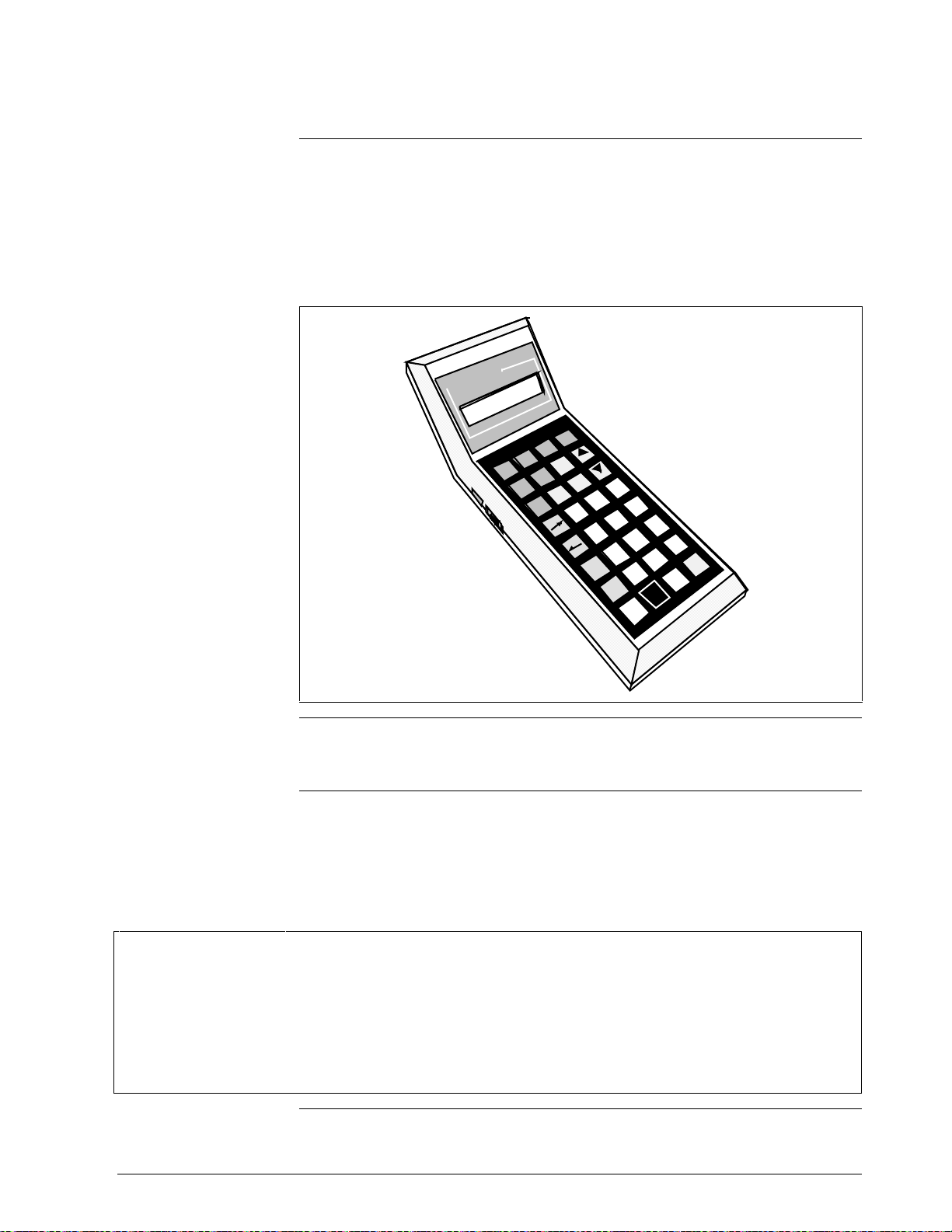
The STS103 is a hand-held unit that has a 2-line by 16-character digital
liquid crystal display (LCD) and a keypad. The STS103 connects to the
SFI by way of a cable connected to the SFI junction box terminals. A
NiCd battery pack allows the STS103 to be used in the field without the
need for input power. The STS103 is shown in Figure 1-1.
Figure 1-1 Smart Field Communicator STS103
l
l
e
w
y
e
n
o
H
N
AG
T
FC
S
.
.
.
G
N
.
I
o
K
R
O
W
S
T
I
N
U
P
M
DA
F
N
O
C
D
I
RV
U
0
1
RV
L
%
0
NU
E
M
M
E
T
I
T
X
NE
T
E
S
%
0
T
U
O
U
P
V
RE
P
R-
O
C
RECT
T
9
8
7
6
5
4
T
A
T
S
3
2
/-
+
1
0
N
A
P
S
H
S
/
M
U
N
A
H
P
L
A
R
E
T
.
F
I
)
N
S
E
E
Y
(
R
L
C
)
O
N
(
T
20330
EMC classification
Industrial Control Equipment, Group 1, Class A, ISM Equipment (ref.
EN 55011).
CE Conformity
(Europe)
This product is in conformity with the protection requirements of
European Council Directive 89/336/EEC, the EMC Directive. Conformity
of this product with any other “CE Mark” Directive(s) shall not be
assumed. Deviation from the operating conditions specified may
invalidate this product’s conformity with the EMC Directive.
ATTENTION
The emission limits of EN 50081-2 are designed to provide reasonable protection against harmful interference
when this equipment is operated in an industrial environment. Operation of this equipment in a residential area
may cause harmful interference. This equipment generates, uses, and can radiate radio frequency energy and
may cause interference to radio and television reception when the equipment is used closer than 30 meters (98
feet) to the antenna(e). In special cases, when highly susceptible apparatus is used in close proximity, the user
may have to employ additional mitigating measures to further reduce the electromagnetic emissions of this
equipment.
Continued on next page
4/99 STS103 Operating Guide 3
Page 16

1.2 STS103 Physical and Functional Description, Continued
2-line by 16-character
LCD display
STS103 keypad
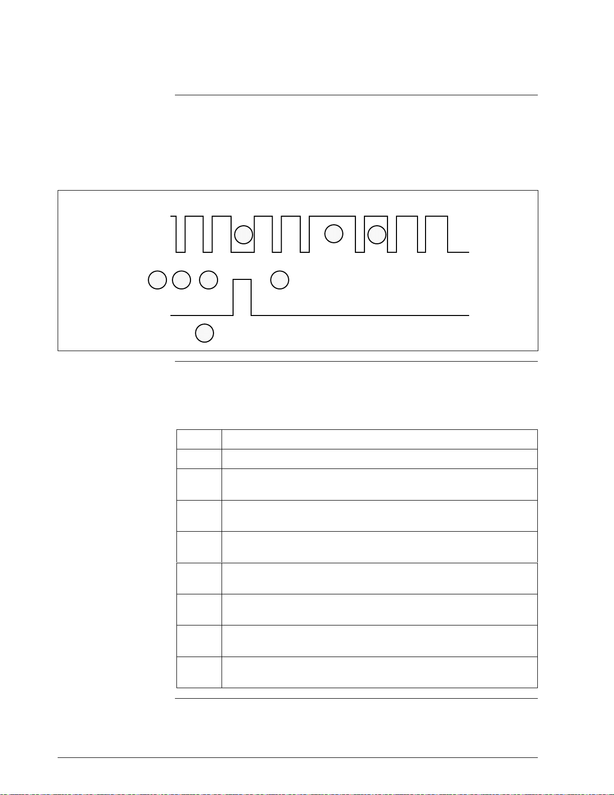
The LCD display provides prompts and displays values, keypad input,
statuses, and alarms. Each character on the display is in a 5 X 7 dot matrix
with a line below the character for the cursor. The STS103 is multi-lingual
and can display parameters and statuses in engineering or metric units.
The desired language is selected through menus, as is the desired
parameter format.
Through the STS103’s keypad, the parameters and characteristics of each
SFI may be viewed and changed. In several instances, several keys are
used together to perform certain functions. Figure 1-2 shows the STS103
keypad and LCD display.
Figure 1-2 STS103 Keypad and LCD Display
L
ABCDEFGHIJKLMNOPQR
ABCDEFGHIJKLMNOP
QRSTUVWXYZ012345
STUVWXYZ1234567890
DE READ
ABCD
CONF
ID DAMP UNITS
EFGH
LRV URV
0% 100%
DE CONF RESET
MENU
A <–> DE
F/S DIR
STAT
SPAN
NUM /
ALPHA
INPUT
IJKL
OUT-
PUT RECTITEM
MNOP
QR ST
UVWX
URL
YZ
SHIFT
SET
COR-
7 8 9
5 64
SW VER
1 2 3
SCR PAD
0
CLR
(NO)
+
NON-VOL
ENTER
20720
NEXT
PREV
–
(YES)
Continued on next page
4 STS103 Operating Guide 4/99
Page 17
1.2 STS103 Physical and Functional Description, Continued
STS103 key functions
Table 1-2 STS103 Key Functions
Key Function
NUM /
ALPHA
^
^^
^
^
S
H
I
F
T
SS
SHH
HII
IFF
FTT
T
S
H
I
F
T
CLR
(NO)
NON-VOL
ENTER
(YES)
DE READ
A
ID
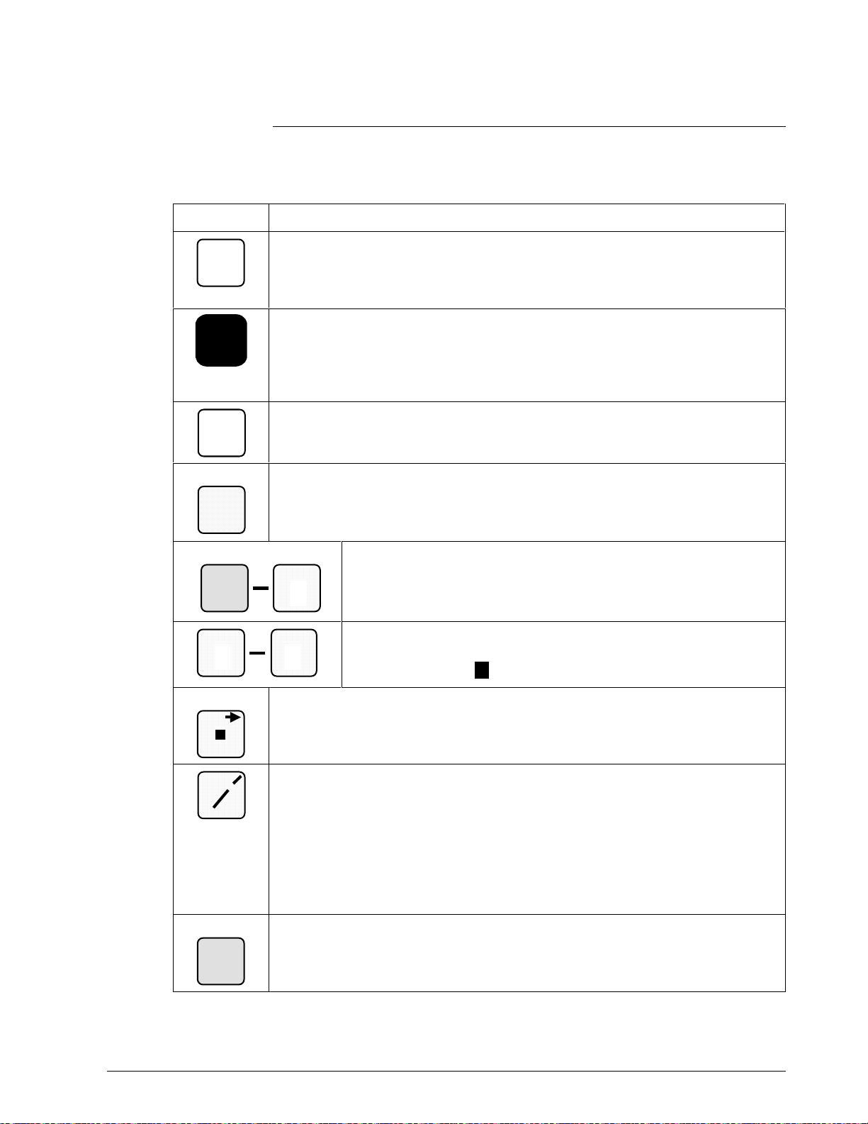
Table 1-2 describes the use and function of the STS103 keypad keys.
The white NUM/ALPHA key toggles between the alpha mode or numeric mode
for the STS103. In the alpha mode, the capital letter or character in the upper
right-hand corner of the keys is input when that key is pressed. In the numeric
mode, the number is input or the indicated first function is performed.
The black SHIFT key enables the second function above certain keys to be
performed. When shifted functions are enabled, the word “SHIFT–” is displayed
on line two of the display. The second function desired must be selected
immediately after the Shift key is pressed. The Shift key upper right-hand
character, the caret character, is input when in the alpha mode.
The white CLR (NO) key cancels the current function or task when pressed and
backs out to its previous operating state. The NO, or negative response, function
is used in response to questions in the LCD display or decisions.
The orange ENTER (YES) (NON-VOL) key is used to send a write/set command
to the RAM memory in an SFI or to answer “Yes” to prompts. The NON-VOL
second function writes data into the non-volatile memory of an SFI.
The Alpha keys A – Z input the alpha character in the upper righthand corner when the alpha mode is activated. The alpha mode is
Z
0
available to enter an ID name or to use the Scratch Pad. The cursor
is replaced by a “
*” character when the alpha mode is activated.
Z
0
SCR PAD
+
–
DE READ
A
ID
P
9
The yellow decimal point (SCR PAD) key inputs a decimal point when in the
number mode and a space in the alpha mode. The SCR PAD second function
displays data in the SFI’s scratch pad memory.
The yellow positive/negative key functions as follows:
•
When entering an ID name or using the Scratch Pad function, the
ALPHA/NUM key toggles to allow a (–) hyphen (NUM mode) or a (/) slash
(ALPHA mode) to be entered using the +/– key.
• In the configuration mode, use the +/– key to enter a positive or negative
symbol when entering a value. The NUM/ALPHA key toggles between “+”
and “–”.
The green ID (DE READ) key reads and displays the device’s tag name (ID)
when pressed. In analog devices, the database is also read. The DE READ
second function reads the digital enhanced SFI’s database along with the tag
name.
The yellow Numeric keys 0 – 9 input the number character when the
number mode is activated. When in the numeric mode, the cursor is
shown as a blinking
.
Continued on next page
4/99 STS103 Operating Guide 5
Page 18
1.2 STS103 Physical and Functional Description, Continued
Key functions,
continued
Table 1-2 STS103 Key Functions (Continued)
Key Description
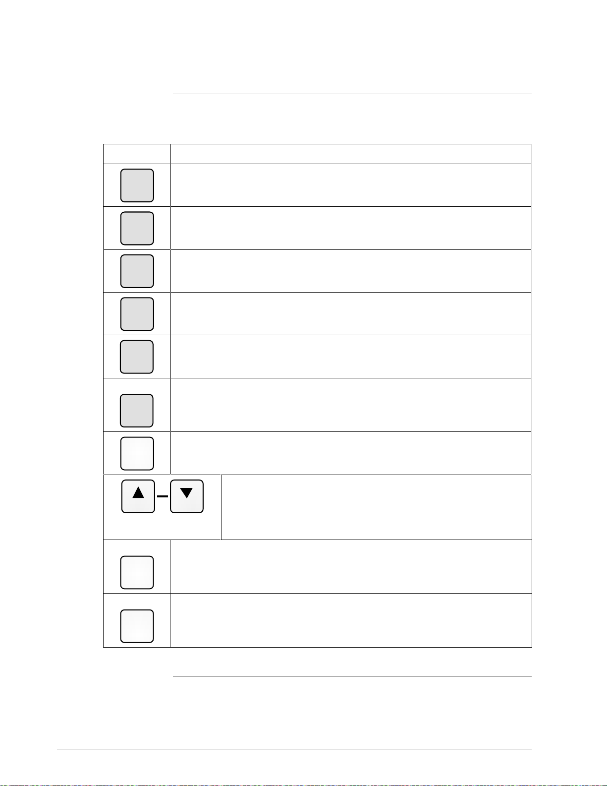
The green CONF key starts each SFI’s configuration mode. The unique settings
B
CONF
DAMP
UNITS
LRV
0%
are the parameters and characteristics that are configured into the SFI.
The green DAMP key displays the damping constant of the SFI. (See Note 1.)
C
The green UNITS key displays the SFI’s currently selected engineering units.
D
The units may be changed by repeatedly pressing the key until the desired units
appear. (See Note 1.)
The green LRV 0% key displays the SFI lower range value (LRV) in the
E
engineering unit selected by the UNITS Key.
(See Note 1.)
F
URV
100%
DE CONF
I
MENU
ITEM
G
SET
H
NEXT
INPUT
J
OUT-
PUT
RESET
K
CORRECT
The green URV 100% key displays the SFI upper range value (URV) in the
engineering unit selected by the UNITS key.
(See Note 1.)
The green MENU ITEM (DE CONF) key selects the current PV from multi-PV
devices. The DE CONF second function displays the current Digital (DE)
configuration. Allows the selection of one data item from a series of grouped
functions in the configuration mode.
The orange SET key sets the function of the key pressed immediately before this
key in the SFI. For example, setting the URV or LRV to the applied PV.
L
The orange NEXT and PREV keys set the damping constant, change
the engineering units, increase and decrease numeric values during
PREV
output D/A calibrations, and displays the next/previous units in the
unit selection. These keys also select the next or previous
configuration element in an SFI’s unique setting mode.
The orange OUTPUT (INPUT) key displays the currently selected transmitted
output in percent. The second function displays the SFI’s currently selected input
in the active engineering units.
The orange CORRECT (RESET) key is used to make on-line zero corrections
and to calibrate output signal and range values. The RESET second function
returns the ST and STT transmitters to their original factory calibration states.
Resetting the MagneW transmitter is done through the calibration menus.
Note 1. For Multi-PV SFI’s, the STS103 displays the value for the currently selected PV.
Continued on next page
6 STS103 Operating Guide 4/99
Page 19
1.2 STS103 Physical and Functional Description, Continued
Key functions,
continued
Table 1-2 STS103 Key Functions (Continued)
Key Description
F/S DIR
STAT
URL
SPAN
SW VER
3
STS103 switch and
terminals
A <–> DE
M Q
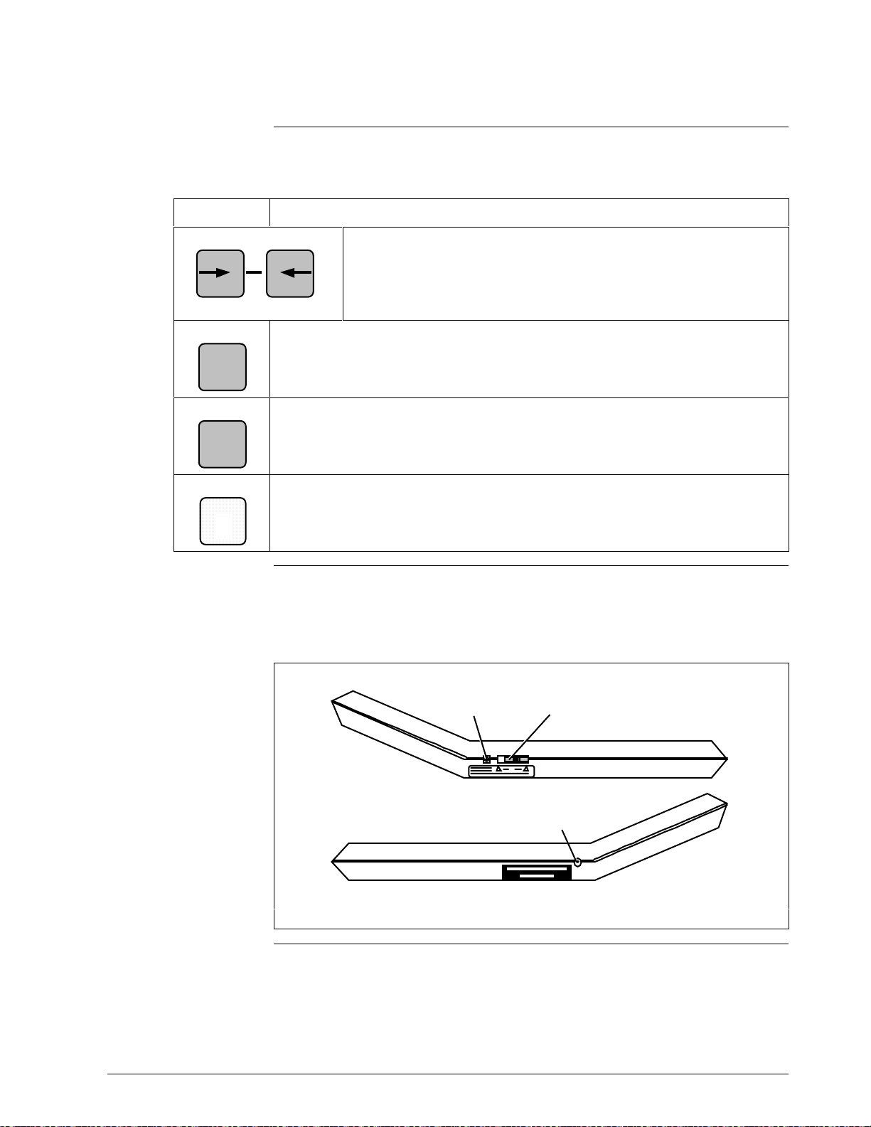
The olive STAT (F/S DIR) key sequentially displays the result of an SFI’s
diagnostics. The second function displays the failsafe direction, Hi or Lo, for
U
analog SFIs. The failsafe direction is hard-wired in the analog SFI and
determines the direction the SFI output goes in burnout (SFI failure).
The olive SPAN (URL) key displays the span in Engineering units selected by the
UNITS key. The second function displays the upper range limit (URL) value of
Y
the SFI.
The yellow 3 (SW VER) key second function displays the software version of the
X
STS103 when not communicating with an SFI, or the software versions of the
STS103 and SFI when connected to an SFI.
Figure 1-3 shows the STS103 ON/OFF switch and the terminals on the
sides of the unit.
Figure 1-3 STS103 Switch and Terminals
The olive cursor keys move the cursor forward or backward one
position while the cursor is displayed. In the number mode, the cursor
back key performs a backspace function. The A <–> DE second
function of the cursor back key toggles the SFI output mode between
analog and digital enhanced communication.
Charging
Terminal
Left Side
4/99 STS103 Operating Guide 7
ON/OFF
Switch
Communications
Terminal
Right Side
20721
Continued on next page
Page 20
1.2 STS103 Physical and Functional Description, Continued
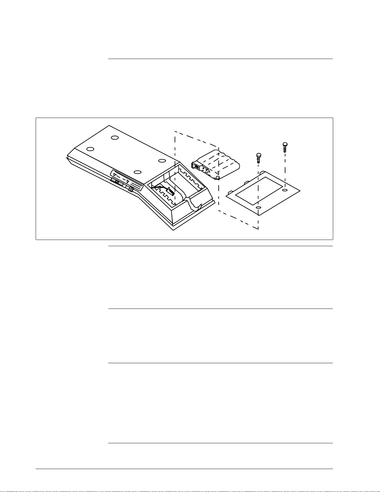
Battery pack location
The battery pack is located behind the LCD display and is accessed
through a back panel. Two hex screws need to be removed to access the
battery pack. Figure 1-4 shows the location of the battery pack and how it
fits into the STS103.
Figure 1-4 STS103 Battery Pack
20722
Charging the batteries
STS103 charging
terminal
Self-diagnostics
The battery pack is charged by plugging the battery charger into an outlet
and inserting the lead into the charging terminal of the STS103. The
battery pack takes a minimum of 10 hours to charge and the STS103 may
be used continuously for up to 24 hours before the battery pack needs
recharging. A colon (:) will be appear in the middle of the top line on the
LCD display when the battery pack needs charging.
The battery pack is charged through a battery charger that plugs into the
charging terminal. The charger inputs 110 or 220 Vac 50/60 Hz and
outputs 7 Vdc 180 mA to the NiCd battery pack. The connector of the
battery charger is inserted into the charging terminal on left side of the
STS103 by the ON/OFF switch.
When the STS103 is turned on, it automatically runs diagnostics on its
functions. Upon successful completion of the diagnostics, the message,
“PUT LOOP IN MAN” (analog communications) or
“DE-XMTR PRESS ID” (digital communications)
appears. If an error occurs, the message,
“CRITICAL STATUS” appears.
Refer to Section 3 for a description of the STS103 errors or the individual
device sections for device specific error messages.
8 STS103 Operating Guide 4/99
Page 21
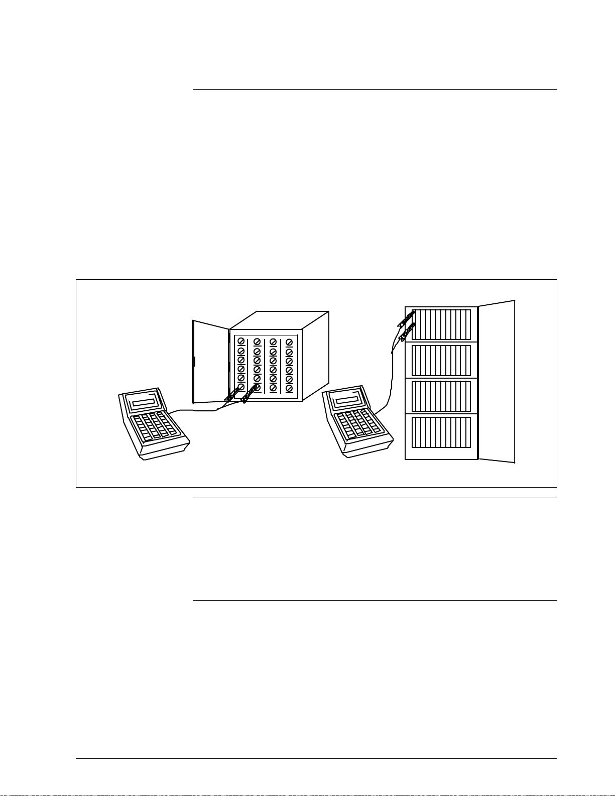
1.3 Connections
Connecting the
STS103 to junction
boxes and IS panels
The STS103 connects to SFIs, IS panels, and junction boxes through a
pair of wires with alligator clips on the ends. The STS103
communications terminal end of the wires has a stereo phone jack
connection that is inserted into the communications terminal. The other
end of the wires are clipped onto terminals in the junction box or IS
barrier panel, or directly to the transmitter. The red SFC lead connects to
the junction box or SFI positive terminal, the black lead to the negative
terminal.
Figure 1-5 shows the STS103 connected to a junction box and an IS
barrier panel.
Figure 1-5 STS103 –Junction Box and IS Connection
Transmitter Junction Box IS Panel
w
l
l
e
w
ey
n
o
H
ney
o
H
l
l
e
Connecting the
STS103 to a smart
field instrument (SFI)
20723
The STS103 connects directly to the positive and negative terminals on
the SFI. The STS103 can connect to only one SFI at a time.
REFER TO THE INDIVIDUAL DEVICE SECTIONS IN THIS
MANUAL for instructions on how to wire the STS103 to your particular
device (SFI).
4/99 STS103 Operating Guide 9
Page 22
1.4 STS103/SFI Communication
How data is
transferred
Types of
communication
Sending and receiving data to and from an SFI is done over the
transmitter’s 4-20 mA wires. When the STS103 is connected to a
transmitter and turned on, it automatically determines what type of
transmitter it is communicating with. When data is sent to a transmitter, a
request is sent to the transmitter and a response is sent back to the
STS103. When the STS103 and SFI are communicating, the message
“SFC Working...” is displayed on the STS103.
The message handling routines are transparent to you. The way the request
and response messages are handled depend on whether the transmitter is
an analog only model or an analog/digital model, and the mode
configuration.
Analog communications uses half duplex communication (data can be
sent in one direction at a time, to the transmitter or to the STS103) while
the digital communication uses half duplex with or without broadcast (4 or
6 bytes). Table 1-3 describes the communication formats used.
Table 1-3 Communication Format Description
Format Description
Analog
Communication
Mode
DE READ
A
ID
Digital (DE)
Communication
Mode
DE READ
^
^^
^
S
SS
SHH
S
^
H
I
F
T
HII
IFF
FTT
T
H
I
F
T
ID
Analog communication uses a half-duplex , variable-length
message with a wake-up pulse for on-demand requests and
responses. While the messages travel back and forth, the
transmitter’s output varies between 4-20 mA, therefore, the
control loop must be in manual so the data exchange does
not interfere with the control loop.
Digital communication also uses a half-duplex , variablelength message with no wake-up pulse for on-demand
requests and responses (not including data uploads). The
data is piggybacked on the process variable data being sent
on the control loop.
The broadcast 4-byte format is rarely used because no
A
database protection can be performed when used in the
TDC 3000 system. This mode is only used when faster PV
update rates are required. One byte is for transmitter status
and configuration data; the other three are for process data.
The broadcast 6-byte format is used for uploading the
transmitter’s database to the STS103’s hold memory. The
bytes are similar to the 4-byte format, but it includes two
additional bytes of transmitter database information.
Continued on next page
10 STS103 Operating Guide 4/99
Page 23
1.4 STS103/SFI Communication, Continued
Analog data exchange
When the STS103 communicates with an analog transmitter, a 26 mA
wake-up pulse is sent to the transmitter to put the device into the
communication mode. The pulse also causes the current drawn by the
device to drop to 4 mA. Data is then exchanged in an analog fashion
(4-20 mA) between the STS103 and SFI. Figure 1-6 shows a typical
analog data exchange using the STS103.
Figure 1-6 Typical Analog Data Exchange
SFC103 Smart Transmitter
Send Request
Keypad Action
Display Message
26 mA
20 mA
Wake-up
Pulse
Wake-up Signal and Message
Data and
Start
Request
Response
Message
Parity
Receive Data
Identify Request
Process Information
Send Response
Stop
Analog PV
10 mA
4 mA
Turn-On
Turn-Off
Request
Start
Response
Data and
Parity
Analog PV
Stop
20724
Continued on next page
4/99 STS103 Operating Guide 11
Page 24
1.4 STS103/SFI Communication, Continued
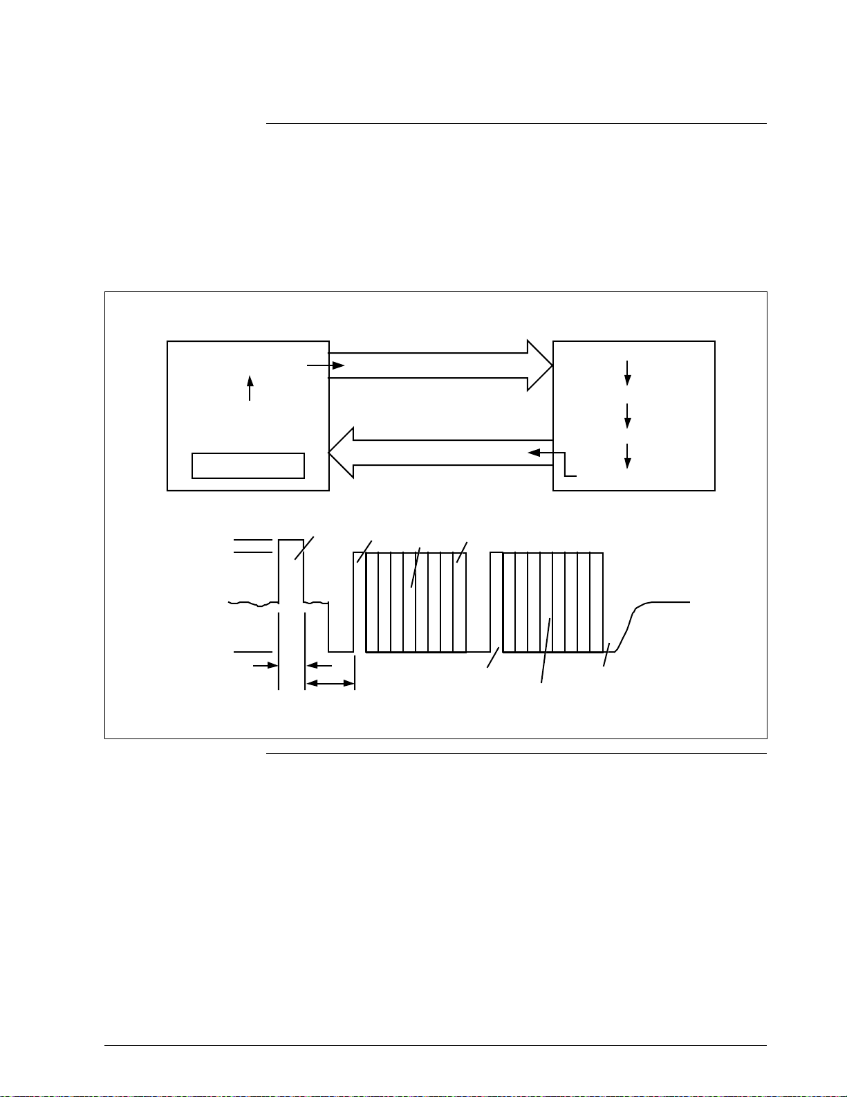
Digital data exchange
Data exchanges between the STS103 and digital devices are in ASCII.
The exchange starts off with the STS103 requesting the transfer and the
SFI then responds. Figure 1-7 shows a typical digital data exchange using
the STS103 and Table 1-4 Describes the sequence of events.
Figure 1-7 Typical Digital Data Exchange
No. of Bytes 4 4 4 4 14 4 4 4
Xmtr
SFC
Digital data exchange
sequence of events
PV PV PV PV
12 3
4
Table 1-4 describes the sequence of events in a typical digital data
exchange. The steps correspond to the numbers in Figure 1-7.
5
Request and
Message
6
7
PV and
Response
8
PV PV PV
20725
Table 1-4 Typical Digital Data Exchange Sequence of Events
Step Occurrence
1 The STS103 waits at least 100 msec for any digital communications.
2 The STS103 detects the transmitter message length and gap
location.
3 The STS103 synchronizes its operation with the next transmitter
message.
4 The STS103 transmits a request and message during the next inter-
message gap.
5 The transmitter halts broadcasting process variable (PV) data when
the request is detected.
6 After receipt of a complete message, the transmitter returns to its
configured broadcast mode and processes a response message.
7 After completion of processing, the transmitter sends the response
message in half duplex protocol after the next PV data broadcast.
8 Upon completion of the data transfer, the transmitter returns to its
configured broadcast mode within 100 msec.
12 STS103 Operating Guide 4/99
Page 25

Section 2 —STS103 User Interface Guidelines
1.2 STS103 Overview
Introduction
What’s in this section?
This section describes the User Interface functions and guidelines for the
STS103 Smart Field Communicator (SFC).
There are several features of the STS103 that will make communicating
with a Smart Field Instrument (SFI) easier to accomplish. They are:
• Common operation for all Smart Field Instruments
• A two-line LCD display
• A new keypad with improved key responsiveness
• Direct key access for the “most used” functions
• Configuration key access for SFI-specific configuration and “lesser
used” functions
This section contains the following topics:
Topic See Page
2.1 Overview 13
2.2 Keypad Functions 14
2.3 Display Functions 15
2.4 Prompt Character Definitions 16
2.5 Function Key Data Entry 17
2.6 Configuration Key Data Entry 19
2.7 Other Key Sequences 21
4/99 STS103 Operating Guide 13
Page 26
2.2 Keypad Functions
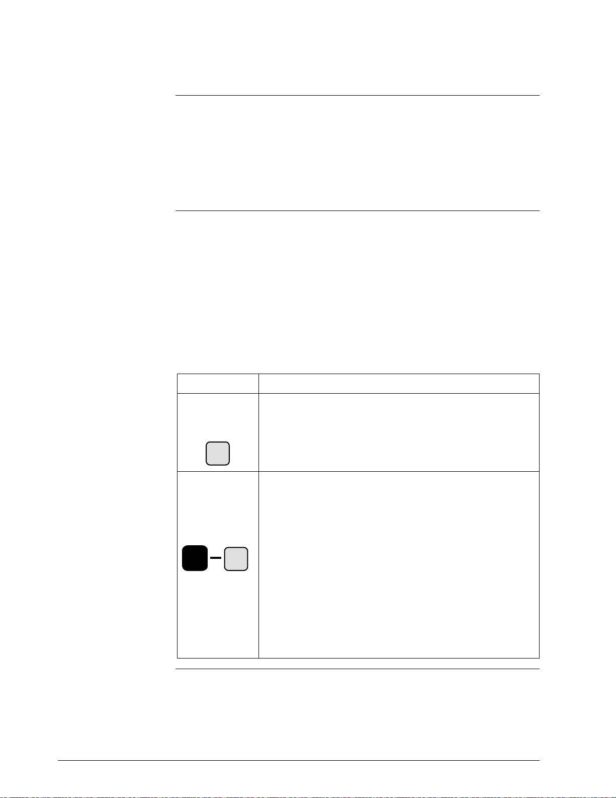
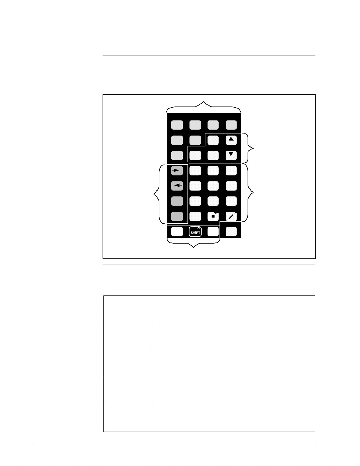
Keypad color groups
The keypad keys are grouped in several different colors that correspond to
specific functions. Figure 2-1 shows the grouping of the STS103 keys.
Figure 2-1 STS103 Keypad Color Groups
Green
DE READ
ABCD
ID DAMP UNITS
CONF
EFGH
Olive
LRV URV
0% 100%
DE CONF RESET
A <–> DE
F/S DIR
ALPHA
INPUT
IJKL
MENU
STAT
NUM /
OUT- COR-
PUT
MNO P
QRST
UVWX
URL
YZ
SHIFT
SET
NEXT
564
PREV
SW VER
+
–
NON-VOL
ENTER
(YES)(NO)
RECTITEM
789
123
SCR PAD
0SPAN
CLR
Orange
Yellow
Orange
Key color group
description
White/Black
20726
Table 2-1 describes the key color grouping on the STS103.
Table 2-1 STS103 Key Color Group Description
Key Color Description
Green
Orange
Yellow
White/Black
Olive
The green keys are used to enter and verify SFI configuration
data.
The orange keys are keys the operator uses to control the
actions of the STS103 and SFIs. These keys also select and
set parameters for the SFIs.
The primary function of the yellow keys is to enter numeric
data into the STS103. Data may be entered into the scratch
pad memory of certain SFIs and the software version may be
displayed through these keys.
The white and black keys enter the alpha or numeric modes
and enable the STS103’s second functions to be activated.
CLR (no) key takes you to a previous function level.
The olive keys allow backspacing or advancing in certain
modes, switching from analog to digital modes for
communicating with different SFIs, and viewing the status of
SFIs. Allows viewing of Span and Upper Range Limit.
14 STS103 Operating Guide 4/99
Page 27

2.3 Display Functions
LCD display
The STS103 uses a two-line display.
Table 2-2 lists the data that may appear on each line of the display and
some examples of each.
Table 2-2 LCD Display Functions
Line Display Data Examples
Upper Type of transmitter MAG SR, LIN DP, STT, etc..
Tag Name (User defined ID name)
A label that identifies the value,
message, or sub-level title on
the lower line.
Configuration sub-level title for
which the menu selections or
settings are shown on the lower
line.
The non critical status indicator ( # )
The low battery indicator ( : )
Lower Alpha-numeric string for ID
name or Scratch Pad entries.
LRV1, OUTPT2, SPT CONFIG,
etc.
RANGE CONFIG?,
PROBE CONFIG?
CONFORMITY?, etc.
(user defined name or message)
The numerical value and units
for the parameter defined on the
upper line.
Configuration sub-level title with
a “?” indicating that the next
configuration level may (“YES”)
or may not (“NO”) be selected
for viewing.
Pre-set or menu selectable
configuration values
(Configuration level 2 or 3).
STS103 processor status
messages.
STS103 communication status
messages.
53.99%, 23.121°C, 28.763 Gal/hr,
etc.
CONFORMITY?,
RANGE CONFIG?,
TOTALIZER MENU?, etc.
CURRENT PV: 1,
F/SAFE UPSCALE,
VELOCITY,
(for MagneW UNITS KEY), etc.
SFC WORKING...,
READY...,
ENTERED IN SFC, etc.
NO TRANSMITTER RESPONSE,
IN OUTPUT MODE, etc.
4/99 STS103 Operating Guide 15
Page 28
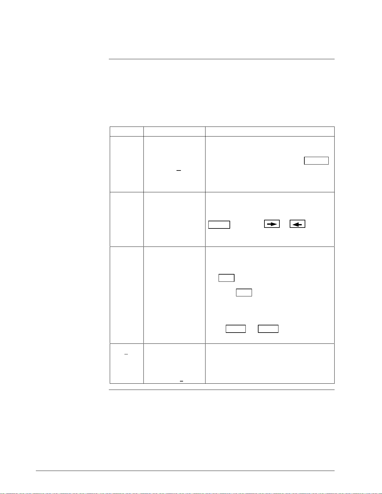
2.4 Prompt Character Definitions
Definitions and general
rules
Certain characters on the LCD display indicate to you which type of
response is permitted.
Table 2-3 shows these characters and the rules and what the STS103 is
looking for in the way of input.
Table 2-3 STS103 LCD Character Definitions and General Rules
Character Display Example Requested Action
“ _ ” When the display
contains a cursor,
for example,
LRV = 1.22
“ = “ When the display
shows an item after
an equal (=) sign,
for example,
F/S = B/O Lo
“ ? ” When the display
shows an item with
a question mark (?)
after the item, for
example,
Range Config?
The STS103 is asking you to enter a
numerical value at the cursor point.
Type in a new value and press the ENTER
key to store the value.
Numeric entries are also allowed in the ID
name and Scratch Pad messages.
The STS103 is asking for a selection after
the equal sign.
Your selection can be made using the
MENU
from a pre-defined list of values or
selections.
The STS103 is asking if you want to enter a
particular group of configuration parameters.
If the parameters are what you desire, press
the YES
Press the CLR
current configuration level and return the
SFC display to the next highest configuration
level.
key or the or
key.
key to cancel from the
keys
Press NEXT
next or previous group of parameters.
“ * “
16 STS103 Operating Guide 4/99
When the display
shows an item with
* “, for example:
a “
ABC
*
The STS103 is asking you to enter an alpha
character.
This prompt is used only when entering an
ID name or Scratch Pad messages.
or PREV to go on to the
Continued on next page
Page 29

2.5 Function Keys Data Entry
Function keys
Multiple process
variables
To access the basic functions or parameters which are common to all
SFIs, press any one of the labeled function keys. These common items
are:
•ID
• SPAN/LRV/URV/URL
• INPUT/OUTPUT
• INPUT and OUTPUT CORRECTS
• LRV and URV CORRECTS and SETS
• RESET CORRECTS
• STATUS
• UNITS
• DAMPING
• FAILSAFE DIRECTION
• DE OPERATIONS
•SW VERSION
• SCRATCH PAD
In some cases, more than one Process Variable is available. Press the
MENU key to select which PV will be referenced when the following
operating parameters are displayed:
• SPAN/LRV/URV/URL/LRL
• INPUT/OUTPUT
• DAMP
• UNITS
For example, consider an SFI that may analyze up to four components.
Each time the MENU key is pressed, the display will step through the
available Process Variables (PVs)-(CURRENT PV:1, CURRENT PV:2,
CURRENT PV:3, CURRENT PV:4).
If PV:2 were selected and the SPAN key pressed, “SPAN 2” (the span
for input 2) would be displayed.
Continued on next page
4/99 STS103 Operating Guide 17
Page 30
2.5 Function Keys Data Entry, Continued
Function key sequence
Most of the common operating parameters are numerical values which
may be altered by the operator. To display and/or change these values,
follow the key sequence procedure in Table 2-4.
Table 2-4 Function Key Sequence
Step Action
1 Press the desired Function key. The display will show the current
setting or value of the selected parameter.
A numerical value may be changed only if the first digit of the
currently displayed value is underlined.
2Enter a new value by pressing the appropriate number keys.
For some values, such as Damping, the
used to step through a menu of permitted selections.
3
Press the ENTER
ATTENTION
the data will not be downloaded to the SFI.
4
The CLR
operating display without making any changes.
key may be used at any time to return to the normal
(yes) key to store the new data in the STS103.
If the operator exits the display using any other key,
and keys may be
18 STS103 Operating Guide 4/99
Page 31

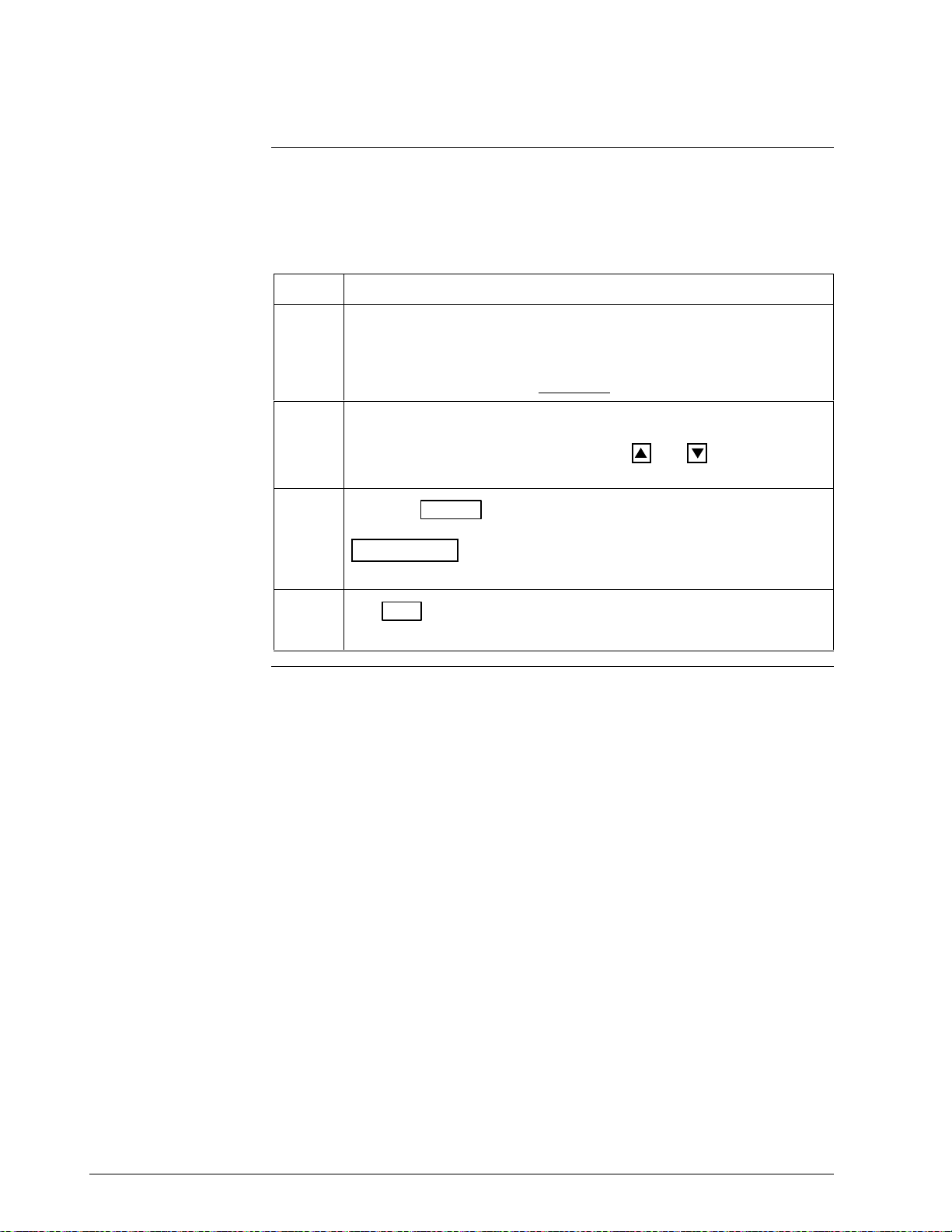
2.6 Configuration Key Data Entry
Configuration key
Configuration key
sequence
Press the CONF key to access SFI-specific configuration menus. SFI
configuration is divided into two or three levels.
• Level 1 – contains a list of configuration categories which is unique
to each SFI.
• Level 2 – contains a list of configuration parameters for each of the
level 1 categories (two level configuration), or
a sub-level of categories which pertains to the level 1
categories (three level configuration).
• Level 3 – contains a list of configuration parameters for each of the
level 2 categories.
To display and/or change configuration, follow the key sequence
procedure in Table 2-5.
Table 2-5 Configuration Key Sequence
Step Action
1
Press the CONF
key.
Configuration level 1 is accessed.
2
Press the NEXT
desired category. The “ ? “ prompt at the end of each selection
indicates:
• the YES
• the NO
the STS103 display to the next higher level.
3
Press the ENTER
displayed. Configuration level 2 (or 3*) is accessed.
* for 3-level configuration, repeat steps 2 and 3 to access level 3.
key will exit the current configuration level and will return
or PREV keys, if necessary, to reach the
key will access configuration level 2 (or 3*).
(yes) key when the desired category is
Table continued on next page
4/99 STS103 Operating Guide 19
Page 32

2.6 Configuration Key Data Entry, Continued
Configuration key
sequence, continued
Table 2-5 Configuration Key Sequence, continued
Step Action
4 At this point you may:
• press the MENU
settings for the displayed parameter, or
• press the
the menu settings, or
• enter a numerical value. (Numbered entries allowed when the first
digit of the current numerical value is underlined.
• press the ENTER (YES) key to enter a new value or setting. The
new data is stored in the SFC and “ENTERED IN SFC” is
displayed.
ATTENTION
setting display, the data will not be changed.
• press the NEXT
parameters within the selected category.
• press the CLR
and return to the next higher level.
5 When any configuration values or settings in a given category have
been updated, the SFC will display the prompt “DOWNLOAD
CHANGES?” before returning to level 1. You may :
key to step through the menu of allowable
or
If you use any other key to exit the new value or
or PREV keys to reach other configuration
(NO) key to exit the current configuration level
keys to step forward or backward through
• press the ENTER
SFI, or
• press the CLR
downloading the new settings to the SFI. Configuration values in
the SFC will also revert to their original setting.
20 STS103 Operating Guide 4/99
(YES) key to download the new settings to the
(NO) key to exit configuration level 1 without
Page 33

2.7 Other Key Sequences
Other keys
Table 2-6 lists several other keys that are available on the keyboard and
how they are used for data entry.
Table 2-6 Other Key Sequences
Key(s) Usage
M
• When entering an ID name or using the Scratch Pad, the right
and left arrow keys move the cursor within any alphanumeric
or
A <–> DE
NUM /
ALPHA
S
H
I
F
SS
SHH
HII
IFF
FTT
S
H
I
F
Q
^
^^
^
^
T
T
T
string.
• These keys are also used to step forward or backward through
the parameter menus in configuration levels 2 and 3 (see
“Configuration Key Method”).
This key toggles the keys of the SFC keyboard between the
function/number printed on the key and the alpha characters
which are printed in the upper right hand corner of each key.
Use this key to enter letters, numbers, “+”, “—”, space, “
^
”, “,”,
“.”, “/” when entering an ID name and when using the Scratch
Pad.
Pressing the SHIFT key, followed by a second key, selects the
function printed above the second key.
CLR
(NO)
The CLR(NO) key:
• clears the current display and returns it to the main “READY”
display (See Function Key Method), or
• clears the current display to the next highest configuration level
(see “Configuration Key Method”), or
• clears a typed-in numerical value before it has been entered
(ENTER
key)
4/99 STS103 Operating Guide 21
Page 34

22 STS103 Operating Guide 4/99
Page 35

3.1 Overview
This section contains all the information you will need to know in order to
operate the STS103 Smart Field Communicator with a Smart Field
Instrument.
Refer to the individual device User’s Manual for transmitter operating and
installation information.
The STS103 operations given here are more or less the same for every
SFI. See the individual device sections in this manual for operations
specific to your particular SFI.
This section gives you the keystrokes and displays that are specific for
SFC communications with the Smart Field Instruments.
Section 3 —STS103 Operation
What’s in this section?
This section contains the following topics:
Topic See Page
3.1 Overview 23
3.2 Power up 24
3.3 Diagnostics and SFC Messages 25
3.4 Common Key Sequences and Displays 28
3.5 Using the Transmitter as a Current Source 43
3.6 Disconnecting the SFC 45
4/99 STS103 Operating Guide 23
Page 36

3.2 Power Up
Power-up key and
display sequences
After connecting the leads directly to the transmitter or through the
junction box or IS panel, and the STS103 is turned on, the key and display
sequences depend on whether your SFI is an Analog or Digital mode
instrument. Figure 3-1 shows the displays and key presses for both modes.
Figure 3-1 Power Up Sequence
Analog Mode Digital Mode
PUT LOOP IN MAN
ID
TAG No.
TRIPS SECURED ?
ENTER
TAG NO.
SFC WORKING...
SFI Type (TAG NO.)
XXXXXXXX
DE-XMTR PRESS ID
ID
TAG NO.
SFC WORKING...
DE XMITTER TAG NO.
XXXXXXXX
20727
When the ID key is pressed, the ID of the device is read in.
For Analog devices, the database is also read in along with the ID.
For digital devices, the second function of the ID key reads in the
database of the digital transmitter. Figure 3-2 shows an example of the
key presses and display that may appear.
Figure 3-2 Read Digital Database
DE READ
A
ID
TAG No
WORKING . . .
(SFI Type) TAG NO .
XXXXXXXX
20728
24 STS103 Operating Guide 4/99
Page 37

3.3 Diagnostics and SFC Messages
Introduction
OK Status
Critical status
The STS103 and the SFIs both run continuous self-diagnostics.
This means that they are constantly testing the communications, the loop,
and themselves.
Any time you want results of these diagnostics, press the STAT key.
The SFC displays its report, in the form of messages, which identify
diagnostic conditions.
Diagnostic conditions are broken down into three categories:
• an OK condition
• a critical condition
• a non-critical condition
An OK condition means no problem exists, and the display looks like this:
STATUS XXXX
STATUS CHECK=OK
A critical condition means that the SFI is not functioning properly. When
this occurs, the SFI goes into upscale burnout and maintains an output of
21.8 mA, or into downscale burnout and maintains an output of less than
3.9 mA. This message CRITICAL STATUS interrupts your operation and
is followed by the message PRESS STATUS.
Non-critical status
Low battery voltage
After the PRESS STATUS message, you press the STAT key to find
out what problem exists. You will receive one or more messages. Take
whatever corrective action necessary to solve the problem. Remember that
the SFI will stay in upscale or down scale burnout until the condition is
corrected.
If the SFI sends more than one message, each message will be displayed
in the order of importance for about 5 seconds. If you need to see them
again, press the STAT key again.
A non-critical condition means that although a problem exists, the SFI is
still operating. When a non-critical condition occurs a “#” character
appears on the right side of the display, along with whatever you’re
displaying at the time.
This character means press the STAT key because some type of a
problem exists. Again, one or more messages will appear on the display
for about five seconds each.
When the battery voltage becomes low, a colon “:” will appear in the
middle of the display. It stays on the display until you either charge or
replace the batteries.
Continued on next page
4/99 STS103 Operating Guide 25
Page 38

3.3 Diagnostics and SFC Messages, Continued
Diagnostic Messages
Table 3-1 is a list of all the diagnostic messages that are common to the
STS103 when used with a Smart Field Instrument (SFI).They are listed in
alphabetical order along with the problem associated with the message and
the corrective action to take when the message appears.
ATTENTION
Refer to the individual device sections for a comprehensive list of error
messages and troubleshooting procedures specific to that particular device.
Table 3-1 Diagnostic Messages for SFC
Message Problem Corrective Action
SFC FAULT
or
SFC FAILURE
COMM ABORTED
ENTRY>SENS RNG
EXCESS ZERO CORR
EXCESS SPAN CORR
FAILED COMM CHK
HI RES/LOW VOLT
H.W. MISMATCH
ILLEGAL RESPONSE
INVALID DATABASE
INVALID REQUEST
SFC communication is not
possible due to a detected SFC
problem.
Communication aborted by user.
The number entered is beyond 1.5
times the upper range limit of the
sensor.
The ZERO correction factor is
outside the acceptable limits for
accurate operation.
The SPAN correction factor is
outside the acceptable limits for
accurate operation.
The SFC failed a communication
diagnostic check. This could be a
SFC electronics problem or a
faulty or dead communication loop.
Either there is too much resistance
in the loop (open circuit), the
voltage is too low, or both.
Hardware mismatch. Part of
Save/Restore function.
SFC received an illegal response
from the SFI.
The database of the SFI was not
correct at power up.
• The SFI is being asked to
correct or set its URV to a value
that results in too low a span, or
being asked to correct its LRV or
URV while in the output mode.
• The given key function is not
valid for the associated SFI.
• Press STAT
messages.
• Replace the SFC.
• Press the CLR
parameter, and start again.
• Check the input and be sure it matches
the calibrated range value.
• Check the input and be sure it matches
the calibrated range value.
• Try communicating again.
• Press the STAT
message appears, do the corrective
action and try again.
• If the Comm error continues, replace the
SFC.
• Check the wiring connections and the
power supply. There must be 11 Volts
minimum at the SFI to permit operation.
• None - SFC tried to restore as much of
the database as possible.
• Try communicating again.
• Try communicating again.
• Verify the database, recalibrate the SFI
and then manually update non-volatile
memory.
• Check that the proper calibrated URV
input is being applied to the SFI, or that
the SFI is not in the output mode.
• Check that the key function is applicable
for your particular SFI.
key to obtain other
key, check the
key. If a loop fault
Table continued on next page
26 STS103 Operating Guide 4/99
Page 39

3.3 Diagnostics and SFC Messages, Continued
Diagnostic Messages,
continued
Table 3-1 Diagnostic Messages for SFC (continued)
Message Problem Corrective Action
IN OUTPUT MODE The SFI is operating as a current
source.
LOW LOOP RES Not enough resistance in series
with the communication loop.
NACK RESPONSE The SFI sent a negative
acknowledgment because one or
more of the commands could not be
processed by the SFI.
NO XMTR RESPONSE No response from the SFI. It may
be a SFI or loop problem.
NVM FAULT Non-volatile memory fault. • Replace the transmitter.
NVM ON SEE MAN The SFC’s CPU is misconfigured • Replace the SFC.
OPTION MISMATCH On a database restore, one or more
options do not match.
>RANGE The value to be displayed is over
the range of the display.
• Press the OUTPUT
you want to exit the output mode.
• Check the sensing resistor and verify at
least 250 Ohms resistance in the loop.
• Check the configuration and try again.
• Try communicating again.
• Press the STAT
corrective action required.
• Check that the flowmeter’s loop integrity
has been maintained and that the SFC is
connected.
• None - SFC tried to restore as much of
the database as possible.
• Press the CLR
and CLR keys if
key and do any
key and start again.
RESTORE FAILED Part of the Save/Restore function. • Check the transmitter and try again.
SENSOR TEMP FAIL The ST 3000 temperature sensor
has failed.
SFC FAULT A component of the SFC is not
operating properly.
STATUS UNKOWN Your SFC has an older version of
software that cannot decode a
“new” diagnostic message from a
more recent transmitter.
TYPE MISMATCH On a database restore, the
transmitter types are not the same.
4/99 STS103 Operating Guide 27
• Replace the transmitter.
• Try communicating again. If the condition
still exists, replace the SFC.
• Put the SFI into the output mode and
press the STAT
identify where the problem is. In the
absence of any other diagnostic
messages, the condition is most likely
meterbody related.
• Check the installation, and if the
condition persists, replace the meter
body.
• None - SFC tried to restore as much of
the database as possible.
key. The message will
Page 40

3.4 Common Key Sequences and Displays
Changing the
communications mode
The Smart Field Instruments operate in either an Analog mode or a Digital
communications (DE) mode. You can quickly change from one mode to
another using the SFC.
See Section 1.4 “STS103/SFI Communication” for format descriptions.
Figure 3-3 is a graphic view of the key presses required to change the
communication mode.
Figure 3-3 Changing Communications Mode
SFI Type (TAG NO.)
READY...
AD
SHIFT
then
From Analog Mode
A/DE (TAG NO.)
CHNG TO DE?
CLR
CLR
From Digital Mode
A/DE (TAG NO.)
CHNG TO ANALOG?
or
ENTER
CLR
SFI Type (TAG NO.)
READY...
A/DE (TAG NO.)
ANALOG XMTR
A/DE (TAG NO.)
ARE YOU SURE?
ENTER
A/DE (TAG NO.)
SFC WORKING...
or
A/DE (TAG NO.)
DE XMTR
20302
Continued on next page
28 STS103 Operating Guide 4/99
Page 41

3.4 Common Key Sequences and Displays, Continued
Selecting configuration
data for the digital
communications mode
You determine how the Digital PV data is handled by configuring the DE
configuration elements shown in Table 3-2.
Table 3-2 DE Configuration Elements
Element Selections And Definitions
Type of Transmitter This element selects the type of transmitter operation. The selections are:
• Single Range Working range PV (PVw) for STDC card or STI
module.
• Single Range W/SV Working Range PV(PVw) with sensor temperature
for STDC card or STI Module.
• Dual Range (STDC) Full range PV (PVt) and Working range PV (PVw)
(For STDC only).
Message Format This element is the message format. The selections are:
• w/o DB (4 Byte) 4 Byte message format (PV or SV only), without
database information.
• W/DB (6 Byte) 6 Byte message format (PV or SV with database
information).
Failsafe Mode for
Digital Control System
This element is the Failsafe mode. You configure the flowmeter to tell the
control system, via the ST/DC card, which failsafe mode to assume when the
card detects a critical failure condition. A critical fault can be due to a critical
status indication from the flowmeter or an extended loss of PV data.
The selections are:
• F/S=B/O Lo Burnout low (drives the PV value to the downscale limit).
• F/S=B/O Hi Burnout high (drives the PV value to the upscale limit).
• LKG Last known good PV value.
• F/S=FSO,B/O Lo Freeze slot output and burnout low (ST/DC card tells
the controller to hold the memory block output at the
preset value and drives input to the controller
downscale to trip alarms).
• F/S=FSO, B/O Hi Freeze slot output and burnout high (ST/DC card tells
the controller to hold the memory block output at the
preset value and drives input to the controller upscale
to trip alarms).
• F/S=LKG Freeze slot output and last known good PV (ST/DC
tells the controller to hold the memory block output at
the present value and provides the last known good PV
value as the input to the controller).
Continued on next page
4/99 STS103 Operating Guide 29
Page 42

3.4 Common Key Sequences and Displays, Continued
Selecting configuration
data for the digital
Figure 3-4 is a graphic view of the key presses required to configure the
elements for DE Communications mode of a Single PV transmitter.
communications mode
(Single PV Transmitters)
Figure 3-4 Configuring the Elements of the DE Communications Mode (Single PV
Transmitter)
SFI Type (TAG NO.)
READY...
SHIFT
DECONF
MENU
NOTE 1
ENTER or NEXT
NOTE 1
ENTER or NEXT
DECONF (TAG NO.)
DOWNLOAD CHANGE?
ENTER
DECONF (TAG NO.)
SFC WORKING...
NOTE 1
ENTER or NEXT
CLR
MENU
DECONF (TAG NO.)
SINGLE RANGE
DECONF (TAG NO.)
SINGLE RANGE W/SV
DECONF (TAG NO.)
DUAL RANGE (STDC)
MENU
DECONF (TAG NO.)
W/O DB (4 BYTE)
DECONF (TAG NO.)
W/DB (6 BYTE)
Note 1. You must press ENTER to store your selection in the SFC.
Press NEXT to move to the next element without storing the previous selection
MENU
DECONF (TAG NO.)
F/S = B/O LO
DECONF (TAG NO.)
F/S =B/O HI
DECONF (TAG NO.)
F/S = LKG
DECONF (TAG NO.)
F/S = FSO,B/O LO
DECONF (TAG NO.)
F/S = FSO, B/O HI
DECONF (TAG NO.)
F/S = FSO, LKG
Continued on next page
20304
30 STS103 Operating Guide 4/99
Page 43

3.4 Common Key Sequences and Displays, Continued
Selecting configuration
data for the digital
Figure 3-5 is a graphic view of the key presses required to configure the
elements for DE Communications mode of a Multiple PV transmitter.
communications mode
(Multiple PV
Transmitters)
Figure 3-5 Configuring the Elements of the DE Communications Mode (Multiple PV
Transmitter)
SFI Type (tag no)
READY...
SHIFT
DE CONF
MENU
DE CONF XXXXXXXX
PV 1 ON W/SV
NEXT
DE CONF XXXXXXXX
PV 2 OFF
MENU
MENU
DE CONF XXXXXXXX
PV 1 ON
DE CONF XXXXXXXX
PV 2 ON
ENTER or NEXT
DE CONF XXXXXXXX
DOWNLOAD CHANGE?
ENTER
DE CONF XXXXXXXX
SFC WORKING...
ENTER
NEXT
DE CONF XXXXXXXX
PV 3 OFF
NEXT
DE CONF XXXXXXXX
PV 4 OFF
or
NEXT
MENU
MENU
DE CONF XXXXXXXX
PV 3 ON
DE CONF XXXXXXXX
PV 4 ON
ENTER
MENU
DE CONF XXXXXXXX
W/O DB (4 BYTE)
DE CONF XXXXXXXX
W/DB (6 BYTE)
ENTER or NEXT
MENU
DE CONF XXXXXXXX
F/S = B/O LO
DE CONF XXXXXXXX
F/S =B/O HI
DE CONF XXXXXXXX
F/S = LKG
DE CONF XXXXXXXX
F/S = FSO,B/O LO
DE CONF XXXXXXXX
F/S = FSO, B/O HI
DE CONF XXXXXXXX
F/S = FSO, LKG
Continued on next page
20729
4/99 STS103 Operating Guide 31
Page 44

3.4 Common Key Sequences and Displays, Continued
Storing data into
non-volatile memory
The following sequence downloads data into the SFI’s non-volatile
memory. Non-volatile memory stores configuration data and retains that
data even after the unit is turned off. This prevents having to reconfigure
the transmitter every time it is turned off. Table 3-3 shows you the key
presses and displays for storing non-volatile memory.
Table 3-3 Storing Data in Non-volatile Memory
Press Displays will Read Result
^
^^
^
^
S
H
I
F
SS
SHH
HII
IFF
FTT
S
H
I
F
then
NON-VOL
ENTER
(YES)
SFI Type TAG NO.
T
T
T
SFC WORKING . . .
SFI Tyoe TAG NO.
DATA NONVOLATILE
SFI Type TAG NO.
READY . . .
then
then
“SFC WORKING” will be displayed as long
as eight seconds.
The data is copied from the Working
memory into the Non-Volatile memory.
Continued on next page
32 STS103 Operating Guide 4/99
Page 45

3.4 Common Key Sequences and Displays, Continued
Damping current
constant
ATTENTION
Damping time sets the unit of time for the damping constant which
establishes the upper limit of frequency response and the response time
characteristics of the transmitter. This is used to reduce the electrical noise
effect on the output signal.
Using the SFC, you can adjust the damping by selecting a value on the
SFC and send that value to the transmitter.
Figure 3-6 is a general view of the key presses required to adjust the
damping time value and also gives you the selections available.
REFER TO THE INDIVIDUAL DEVICE SECTIONS FOR THE
MINIMUM AND MAXIMUM DAMPING VALUES ALLOWED FOR
YOUR SFI AND A MORE DEFINITIVE ENTRY PROCEDURE.
Figure 3-6 Adjusting the Damping Time Value
SFI Type (TAG NO.)
READY...
DAMP
DAMPX (TAG NO.)
X.X SECONDS
NOTE 1
or
DAMPX (TAG NO.)
SFC WORKING...
DAMPX (TAG NO.)
(NEW VALUE)
ENTER CLR
Note 1. See the individual device
sections for available damping settings.
20730
Continued on next page
4/99 STS103 Operating Guide 33
Page 46

3.4 Common Key Sequences and Displays, Continued
Displaying, setting,
and calibrating the
Figure 3-7 is a general view of the key presses required to display, set, or
calibrate the Lower Range Value (LRV) on most SFIs.
lower range value
ATTENTION
REFER TO THE INDIVIDUAL DEVICE SECTIONS FOR A MORE
DEFINITIVE ENTRY PROCEDURE.
Figure 3-7 Displaying, Setting, and Calibrating the Lower Range Value
SFI Type (TAG NO.)
READY...
LRV
0%
LRVX (TAG NO.)
XXX (UNITS)
to
0
to change value
9
LRVX (TAG NO.)
XXX (UNITS)
G
SET
LRVX (TAG NO.)
SET LRV?
CLR
LRVX (TAG NO.)
XXX (UNITS)
RESET
K
CORRECT
LRVX (TAG NO.)
CORRECT LRV?
CLR
LRVX (TAG NO.)
(NEW VALUE) (UNITS)
ENTER
LRVX (TAG NO.)
(NEW VALUE) (UNITS)
CLRENTER or
CLR
NON-VOL
ENTER
(YES)
LRVX (TAG NO.)
SFC WORKING. . .
LRVX (TAG NO.)
(VALUE) (UNITS)
CLRENTER or
NON-VOL
ENTER
(YES)
LRVX (TAG NO.)
SFC WORKING. . .
LRVX (TAG NO.)
(VALUE) (UNITS)
CLRENTER or
20731
Continued on next page
34 STS103 Operating Guide 4/99
Page 47

3.4 Common Key Sequences and Displays, Continued
Displaying, setting,
and calibrating the
Figure 3-8 is a general view of the key presses required to display, set, or
calibrate the Upper Range Value (URV) on most SFIs.
upper range value
ATTENTION
REFER TO THE INDIVIDUAL DEVICE SECTIONS FOR A MORE
DEFINITIVE ENTRY PROCEDURE.
Figure 3-8 Displaying, Setting, and Calibrating the Upper Range Value
SFI Type (TAG NO.)
READY...
F
URV
100%
URVX (TAG NO.)
XXX (UNITS)
to
0
to change value
9
URVX (TAG NO.)
XXX (UNITS)
G
SET
URVX (TAG NO.)
SET URV?
CLR
URVX (TAG NO.)
XXX (UNITS)
RESET
K
CORRECT
URVX (TAG NO.)
CORRECT URV?
CLR
URVX (TAG NO.)
(NEW VALUE) (UNITS)
ENTER
URVX (TAG NO.)
(NEW VALUE) (UNITS)
CLRENTER or
CLR
NON-VOL
ENTER
(YES)
URVX (TAG NO.)
SFC WORKING. . .
URVX (TAG NO.)
(VALUE) (UNITS)
CLRENTER or
NON-VOL
ENTER
(YES)
URVX (TAG NO.)
SFC WORKING. . .
URVX (TAG NO.)
(VALUE) (UNITS)
CLRENTER or
20732
Continued on next page
4/99 STS103 Operating Guide 35
Page 48

3.4 Common Key Sequences and Displays, Continued
Displaying and
changing the span
of the device
Figure 3-9 is a general view of the key presses required to read or change
the span between the upper and lower measuring limits on most SFIs.
Figure 3-9 Displaying and Changing the Span
SFI Type (TAG NO.)
READY...
URL
Y
SPAN
SPAN x (TAG NO.)
XXX (UNITS)
to
0
to change value
SPAN x (TAG NO.)
(NEW VALUE) (UNITS)
9
CLR
ENTER
SPAN x (TAG NO.)
(NEW VALUE) (UNITS)
CLRENTER or
20733
Continued on next page
36 STS103 Operating Guide 4/99
Page 49

3.4 Common Key Sequences and Displays, Continued
Displaying and
changing the upper
range limit of the
device
Figure 3-10 is a general view of the key presses required to read or change
the Upper Range Limit on most SFIs.
Figure 3-10 Displaying and Changing the Upper Range Limit
SFI Type (TAG NO.)
READY...
URL
Y
SPAN
URLx (TAG NO.)
XXX (UNITS)
to
0
to change value
9
URL x (TAG NO.)
(NEW VALUE) (UNITS)
ENTER
URL x (TAG NO.)
(NEW VALUE) (UNITS)
CLRENTER or
CLR
20734
Continued on next page
4/99 STS103 Operating Guide 37
Page 50

3.4 Common Key Sequences and Displays, Continued
Resetting the SFI
The sequence below, commonly known as Corrects-Reset, shows how to
reset most devices to their factory default setting. Corrects-Reset is
performed when you need to reset and recalibrate the SFI.
The MagneW 3000 default settings are in the calibration hierarchy called
“shipping data.”. See the device section for the procedure.
Figure 3-11 is a general view of the key presses required to reset to
factory default settings on most SFIs.
Figure 3-11 Corrects Reset
SFI Type (TAG NO.)
READY...
RESET
K
CORRECT
(TAG NO.)
RESET CORRECTS?
CLR
ENTER
(TAG NO.)
SFC WORKING . . .
(TAG NO.)
CORRECTS RESET?
20735
Continued on next page
38 STS103 Operating Guide 4/99
Page 51

3.4 Common Key Sequences and Displays, Continued
Clear Output
Displaying, setting,
and clearing the
current output
The OUTPUT key has four uses:
• View the output of the transmitter in percent of span,
• Put the transmitter in the current output mode, (see Section 3.5).
• Clear the current output mode, and
• Correct 0% value of the DAC and the span of the DAC (100% value).
Figure 3-12 is a general view of the key presses required to display and set
the output value and clear the current output mode.
The sequence on the left shows how to display the output value and set the
output mode. The sequence on the right shows how to clear the output
mode.
ATTENTION
REFER TO THE INDIVIDUAL DEVICE SECTIONS FOR ZERO AND
SPAN DAC CORRECTIONS.
Figure 3-12 Displaying, Setting, and Clearing the Current Output.
Display/Set
Output Value
INPUT
J
OUT-
PUT
Mode
INPUT
OUTPUT
J
OUTP1 (TAG NO) #
SFC WORKING . . .
OUTP1 (TAG NO) #
XX.XX %
Z
0
to change output value
OUTP1 (TAG NO) #
100.00 %
NON-VOL
ENTER
(YES)
OUTP1 (TAG NO) #
SFC WORKING . . .
OUTP1 (TAG NO) #
100.00 %
P
9thru
example
OUTP1 (TAG NO) #
SFC WORKING . . .
Note 1.
Note 1. # sign indicates a non-critical status
In this case it indicates that the SFI is in the
Output Mode.
OUTP1 (TAG NO) #
XX.XX %
CLR
(NO)
OUTP1 (TAG NO) #
SFC WORKING . . .
SFI Type (TAG NO)
READY
20736
Continued on next page
4/99 STS103 Operating Guide 39
Page 52

3.4 Common Key Sequences and Displays , Continued
Displaying and
calibrating the current
input value
Figure 3-13 is a view of the key presses required to display and calibrate
the input value.
The sequence below is followed when viewing and/or calibrating most
SFI’s input value. This function is not available for STT 3000 devices.
Figure 3-13 Displaying and calibrating the Current Input Value
SFI Type (TAG NO)
READY . . .
INPUT
J
OUT-
PUT
INPUT 1 (TAG NO)
SFC WORKING . . .
CLR
(NO)
INPUT 1 (TAG NO)
(value) (units)
INPUT 1 (TAG NO)
ZERO INPUT?
NOTE 1.
NON-VOL
ENTER
(YES)
INPUT 1 (TAG NO)
SFC WORKING . . .
INPUT 1 (TAG NO)
INPUT ZEROED
RESET
K
COR-
RECT
CLR
(NO)
Note 1. A Zero equivalent input must
be applied at this point for the
Correct to work.
20737
Continued on next page
40 STS103 Operating Guide 4/99
Page 53

3.4 Common Key Sequences and Displays, Continued
Displaying the SFI
diagnostic status
Figure 3-14 is a view of the key presses required to display the SFI’s
diagnostic status.
Figure 3-14 Displaying the SFI Diagnostic Status
F/S DIR
U
STAT
SFI Type (TAG NO)
WORKING . . .
No Errors
Any Errors
(Example)
SFI Type (TAG NO) #
IN OUTPUT MODE
SFI Type (TAG NO)
CORRECTS RESET
SFI Type (TAG NO)
STATUS CHECK = OK
20738
When any errors are detected, each error is displayed for 2 seconds. The
message received as a response from the SFI may then be looked up under
the specific status messages for that SFI which are shown in each device
section.
Displaying the
software version
Figure 3-15 is a view of the key presses required to display the SFI’s
software version. Use the sequence to call up the software version of the
STS103 and connected SFI. If the STS103 is not connected to an SFI,
only the software version of the STS103 is displayed.
Figure 3-15 Software Version
SW VER
X
3
SFI Type (TAG NO)
SFC = 5.0 XMTR = 3.0
H
or
NEXT
SFI Type (TAG NO)
05-03-1993 10:04
L
PREV
20739
Continued on next page
4/99 STS103 Operating Guide 41
Page 54

3.4 Common Key Sequences and Displays, Continued
Writing data in the
scratch pad area
Procedure
A unique feature of Smart Field Instruments is their ability to store user
messages in the scratch pad area of its non-volatile memory. This feature
allows you to enter (write) a message or messages consisting of a total of
32 characters in two groups of 16 each (Scratch Pad 1 and Scratch Pad 2).
Use the procedure in Figure 3-16 to enter the scratch pad area and step the
cursor through each scratch pad display.
The following are some rules to remember when entering data:
• Use the NUM/ALPHA key to switch between alpha and numeric
characters.
• Use the or to step forward and backward through the text
for editing.
• For spaces use the • key when in the alpha mode.
Figure 3-16 Writing Data in Scratch Pad Area
SCR PAD
SFI Type (TAG NO)
SFC WORKING . . .
SCRATCH PAD1 1
X
XXXXXXXXXXXXXXX
NUM /
to switch between Alpha and numeric mode
ALPHA
A <–> DE
M
DE READ
A
ID
thru
Z
0 thru
SCRATCH PAD 1
THIS IS TEST 001
CLR
(NO)
SFI Type (TAG NO)
READY . . .
Q
0
9
Example
H
NEXT
to step forward and backward through text
Z
to enter Alpha characters
P
to enter numbers
NEXT
L
SCRATCH PAD1 2
PREV
X
XXXXXXXXXXXXXXX
L
H
PREV
SCRATCH PAD 2
THIS IS TEST 001
NON-VOL
ENTER
(YES)
20740
42 STS103 Operating Guide 4/99
Page 55

3.5 Using the Transmitter as a Current Source
Introduction
ATTENTION
One of the unique features of a Smart Field Instrument is its ability to be
used as a constant current-source. This feature allows you to use it for
calibrating other instruments in the loop such as recorders, controllers, and
positioners.
As you know, the output of the SFI ranges from 4 to 20 milliamps where
4 mA = 0% output and 20 mA = 100% output. Using the STS103, you can
tell the SFI to change its output to any value between 0 and 100% and
maintain that output. Then you can use this output as a calibration input
source to the other instruments in the loop.
Note that the current “output mode” overrides all other PV data from the
SFI including the burnout data in the Digital Communications mode.
When you use the SFI as a current source, it no longer acts as a SFI. Make
sure to clear this output mode when you are finished.
Continued on next page
4/99 STS103 Operating Guide 43
Page 56

3.5 Using the Transmitter as a Current Source, Continued
Procedure
Connect an ammeter to read the output of the SFI and connect the STS103
Smart Field Communicator to the SFI. Follow the procedure listed in
Table 3-4 to use the SFI as a constant current-source.
Table 3-4 Using the SFI as a Constant Current-source
Step Press Display Example Result or Action
1
2
3 Check the output reading and see that it reads
INPUT
OUT-
PUT
SW VER
3
0
NON-VOL
ENTER
(YES)
J
OUTP1 TAG NO.
SFC WORKING . . .
then
OUTP1 TAG NO. #
32.4 %
X
OUTP1 TAG NO.
SFC WORKING . . .
then
Z
OUTP1 TAG NO. #
30.00 %
Your display will look similar to this with your output
displayed and it will update every 6 seconds.
Remember, when you’re ready to press the next key,
to wait for the updated display.
Key in the output you want. For this example, we will
use 30%.
The display will show the output with a decimal point
and two zeros. Also, the SFC adds a “#” character (a
non-critical status indicator) on the right side of the
display to remind you that in this case you are in the
output mode. It will stay on the display as long as
your SFI is being used as a current-source.
8.8 mA, which is equal to a 30% output.
If your meter shows a different reading or no “#”
character appears on the display, go back to the
beginning of this procedure and start over.
Try a few different percentages and check your
meter with the list below:
Key-in this value Your meter reads
0% 4.0 mA
25% 8.0 mA
50% 12.0 mA
60% 13.6 mA
80% 16.6 mA
100% 20.0 mA
4
CLR
(NO)
OUTP1 TAG NO.
SFC WORKING . . .
This clears the output mode.
Notice that the “#” character disappeared.
then
SFI Type TAG NO.
READY . . .
ATTENTION
If you do not press the CLR key
and press another key you will not exit the output
mode. This means that you cleared the display but
are still in the output mode.
44 STS103 Operating Guide 4/99
Page 57

3.6 Disconnecting the SFI
Check list
Before you disconnect the STS103 from the Smart Field Instrument, refer
to Table 3-5 and follow the Check List given.
Table 3-5 Disconnect Check List
Check Press Display Example Result or Action
1 Be sure the SFI is not in the Output mode or any
other error condition. The SFC displays a “#”
character on the upper right side of the display
indicating the output mode or other non-critical
status.
2
3
INPUT
OUTPUT
then
CLR
(NO)
^
^^
^
^
S
H
I
F
SS
SHH
HII
IFF
FTT
S
H
I
F
then
NON-VOL
ENTER
(YES)
J
OUTP1 TAG NO.
SFC WORKING . . .
This clears the output mode.
Notice that the “#” character disappeared.
then
SFI Type TAG NO.
READY . . .
ATTENTION
If you press the CLR key without
pressing the OUTPUT
key, the “#” character stays
on the display. This means that you cleared the
display but are still in the output mode.
T
T
T
SFI Type TAG NO.
READY . . .
then
SFI Tyoe TAG NO.
DATA NONVOLATILE
“SFC WORKING” will be displayed as long as eight
seconds.
The data is copied from the Working memory into the
Non-Volatile memory.
then
SFI Type TAG NO.
READY . . .
4 Be sure the STS103 is disconnected from the Smart
Field Instrument before returning the loop to the
automatic operating mode.
4/99 STS103 Operating Guide 45
Page 58

Page 59

Section 4 —ST 3000 Pressure Transmitter
4.1 Overview
Introduction
What’s in this section?
This section contains all the information you will need to know in order to
wire, set-up, configure, operate, calibrate, and troubleshoot the ST 3000
Pressure Transmitter using the STS103 Smart Field Communicator.
Refer to the ST 3000 User’s Manual for transmitter operating and
installation information.
Make sure you have become familiar with the STS103 operations that are
more or less the same for every transmitter.
This section gives you the keystrokes and displays that are specific for
SFC communications with the ST 3000 Pressure Transmitter.
This section contains the following topics:
Topic See Page
4.1 Overview 47
4.2 Wiring 48
4.3 Set-up 50
4.4 Configuration 62
4.5 Output Calibration 64
4.6 Operation 67
4.7 Diagnostics and SFC Messages 71
4.8 Troubleshooting 75
4/99 STS103 Operating Guide 47
Page 60

4.2 Wiring
Overview
Connecting the
STS103 to junction
boxes and IS panels
Establish communications with the ST 3000 by connecting the SFC leads
to the 4–20 mA line of the transmitter.
Your choices are either at a junction box somewhere along the 4–20 mA
line, on the field side of the intrinsic safety barrier panel in the control
room, or at the transmitter itself.
Following are examples for connecting to all these places. Use the one
you need.
The STS103 connects to ST 3000 transmitters, IS Panels, and junction
boxes through a pair of wires with alligator clips on the ends. The STS103
communications terminal end of the wires has a stereo phone jack
connection that is inserted into the communications terminal. The other
end of the wires are clipped onto terminals in the junction box or IS
barrier panel, or directly to the transmitter. The red SFC lead connects to
the junction box or SFI positive terminal, the black lead to the negative
terminal.
Figure 4-1 shows the STS103 connected to a junction box or an IS barrier
panel.
Figure 4-1 STS103 – Junction Box and IS Connection
Transmitter Junction Box IS Panel
e
yw
e
l
l
e
w
ey
n
o
H
n
o
H
l
l
20723
Continued on next page
48 STS103 Operating Guide 4/99
Page 61

4.2 Wiring, Continued
STS103 - ST 3000
connection
Figure 4-2 shows the STS103 connected directly to the positive and
negative signal terminals on a typical ST 3000 transmitter. The STS103
can connect to only one ST 3000 at a time.
Figure 4-2 STS103–ST 3000 Connections
ST 3000 Smart
Pressure
Transmitter
250 oh ms
+
-
L
-
+
-
Housing
End Cap
+
SIGNAL
-
+
TEST
-
+ Red
WARNING
STS103 charging
terminal
+
-
24Vdc
Power
Supply
SFC
20741
When the junction box cover on the transmitter is removed, the housing is
NOT explosion-proof.
The NiCd battery pack is charged through a battery charger that plugs into
the charging terminal. The charger inputs 110 or 220 Vac 50/60 Hz and
outputs 7 Vdc 180 mA to the NiCd battery pack.
The connector of the battery charger is inserted into the charging terminal
on left side of the STS103 near the ON/OFF switch.
4/99 STS103 Operating Guide 49
Page 62

4.3 Set-up
Overview
Keying in the I.D. and
uploading the database
ATTENTION
Setting up the ST 3000 Pressure Transmitter consists of:
• Keying-in the I.D. and loading the Database.
• Adjusting the Damping time.
• Selecting the units in which to display values.
• Selecting the ST 3000’s communication mode.
• Selecting the type of configuration for the transmitter in the Digital
Communications (DE) Mode.
• Keying-in the Lower Range value and Upper Range value (Span)
using the keyboard.
• Keying-in the Lower Range value and Upper Range value (Span)
using applied pressure.
The procedure listed in Table 4-1 gives you the steps required to key–in
an ID and upload the database for the ST 3000.
You will note in the procedure that:
• The database for an Analog transmitter is automatically read or
uploaded to the SFC when you press ENTER in response to the
“TRIPS SECURED” prompt.
• The database for a Digital transmitter is read or uploaded when you
press the SHIFT I D keys.
Table 4-1 Keying–in the ST 3000 ID and Uploading the Database Procedure
Step Press SFC Display will Read Result
ANALOG TRANSMITTERS (For Digital Transmitters - see step 4)
1
DE READ
ID
NON-VOL
ENTER
(YES)
A
TAG NO.
TRIPS SECURED?.
TAG NO.
SFC WORKING . . .
Then
(SFI Type) TAG No.
XXXXXXXX
The database is loaded into the SFC at this point
for analog transmitters.
The top line identifies the type of pressure
transmitter and the Output form. (for example:
LIN DP = Linear output, Differential Pressure)
Notice the line under the first character of the ID
on the bottom line. This is the cursor and
indicates where you can key–in an ID.
Alpha/numeric entries of up to 8 characters are
permitted.
If the ST 3000 was not given an ID, the line will
be blank with a cursor.
Table continued on next page
50 STS103 Operating Guide 4/99
Page 63

4.3 Set-up, Continued
Keying–in the ID and
uploading the
database, continued
Table 4-1 Keying–in the ST 3000 ID and Uploading the Database Procedure (continued)
Step Press SFC Display will Read Result
ANALOG TRANSMITTERS, continued
2
NUM /
ALPHA
until you
see
3
NON-VOL
ENTER
(YES)
DIGITAL TRANSMITTERS
4
DE READ
A
ID
(SFI Type) TAG No.
*
or
(SFI Type) TAG No.
(SFI Type) TAG No.
SFC WORKING . . .
then
(SFI Type) TAG No.
(New ID)
TAG NO.
SFC WORKING . . .
Then
DE-XMTR TAG No.
XXXXXXXX
An * indicates that the prompt is looking for an
alpha character. The letters are located in the
upper right corner of the keys.
indicates the prompt is looking for a number.
A
The numbers are on the yellow keys.
Press NUM/ALPHA
key to change from Alpha
to Numeric mode or vice versa.
One of the symbols appears on the display and
in place of the first character of the old ID. The
rest of the old ID disappears.
Key–in your ID using the NUM/ALPHA
key and
the letters and numbers on the keys.
The ID is loaded into the transmitter.
The top line indicates that the transmitter is
configured for DE Communications mode.
Notice the line under the first character of the ID
on the bottom line. This is the cursor and
indicates where you can key–in an ID.
Alpha/numeric entries of up to 8 characters are
permitted.
If the ST 3000 was not given an ID, the line will
be blank with a cursor.
5
NUM /
ALPHA
until you
see
(SFI Type) TAG No.
*
or
(SFI Type) TAG No.
An * indicates that the prompt is looking for an
alpha character. The letters are located in the
upper right corner of the keys.
indicates the prompt is looking for a number.
A
The numbers are on the yellow keys.
Press NUM/ALPHA
key to change from Alpha
to Numeric mode or vice versa.
One of the symbols appears on the display and
in place of the first character of the old ID. The
rest of the old ID disappears.
Key–in your ID using the NUM/ALPHA
key and
the letters and numbers on the keys.
Table continued on next page
4/99 STS103 Operating Guide 51
Page 64

4.3 Set-up, Continued
Keying–in the ID and
database, continued
Table 4-1 Keying–in the ST 3000 ID and Database Procedure (continued)
Step Press SFC Display will Read Result
DIGITAL TRANSMITTERS, continued
6
NON-VOL
ENTER
(YES)
(SFI Type) TAG No.
SFC WORKING . . .
then
(SFI Type) TAG No.
(New ID)
The ID is loaded into the transmitter.
7
S
SS
SHH
S
^
^^
^
^
H
I
F
T
HII
IFF
FTT
T
H
I
F
T
then
DE READ
A
ID
Copying data into
non-volatile memory
(SFI Type) TAG No.
SFC WORKING – XX%
then
(SFI Type) TAG No.
(New ID)
This loads the Digital Transmitter database to the
SFC.
The display indicates the percent of the database
being loaded until it reaches 100%.
When setting-up or configuring a ST 3000, whether you are changing one
element or a full database, you must copy all configuration data into the
transmitter’s non-volatile memory. This is the transmitter’s permanent
memory. If the transmitter were to lose power, the values for the database
will be saved here.
The transmitter also contains a working memory that loses its contents if
the power goes off; and when power is restored, the transmitter copies the
contents of the non-volatile memory into the working memory.
There is a failsafe procedure. Thirty seconds after a value is changed, the
transmitter automatically copies it into the non-volatile memory. But, if
you change an element and power goes down before this runs, you will
still lose the data in the working memory. Therefore, whenever you make
any changes in the transmitter, always end your procedure as follows:
Press Displays will Read Result
^
^^
^
^
S
H
I
F
SS
SHH
HII
IFF
FTT
S
H
I
F
then
NON-VOL
ENTER
(YES)
(SFI Type) TAG No.
T
T
T
SFC WORKING . . .
(SFI Type) TAG No.
DATA NONVOLATILE
(SFI Type) TAG No.
READY
then
then
“SFC WORKING” will be displayed as long
as eight seconds.
The data is copied from the Working
memory into the Non-Volatile memory.
Continued on next page
52 STS103 Operating Guide 4/99
Page 65

4.3 Set-up, Continued
Adjusting the
damping time
Damping time sets the unit of time for the damping constant. This
constant establishes the upper limit of frequency response and the
response time characteristics of the transmitter. This is used to reduce the
electrical noise effect on the output signal.
Using the SFC, you can adjust the damping by selecting a value on the
SFC and send that value to the transmitter.
• The minimum value is 0.0 seconds (no damping).
• The maximum value is 32.0 seconds.
Figure 4-3 is a graphic view of the key presses required to adjust the
damping time value and also gives you the settings available.
You can also key–in a value using the numbered yellow keys but the
value will default to the closest value listed.
Figure 4-3 Adjusting the ST 3000 Damping Time Value
(SFI Type) TAG No.
READY...
DAMP
CLR
DAMPX (TAG NO.)
X.X SECONDS
NOTE 1
or
DAMPX (TAG NO.)
SFC WORKING...
DAMPX (TAG NO.)
(NEW VALUE)
NOTE 1
ENTER CLR
NOTE 1: Available Damping Settings are: 0.0, 0.2, 0.3, 0.5, 1.0, 2.0, 4.0, 8.0, 16.0,
32.0 seconds
to key in value
90
thru ENTER
DAMPX (TAG NO.)
SFC WORKING...
DAMPX (TAG NO.)
(NEW VALUE)
ENTER CLR
20322
Continued on next page
4/99 STS103 Operating Guide 53
Page 66

4.3 Set-up, Continued
Selecting the units in
which to display values
Although the most common units for measuring pressure are inches of
water or pounds per square inch, you may want it shown in another unit.
The SFC Model STS103 (Software Rev. 3.2 and up) can display the
values for LRV, URV, SPAN, URL, and INPUT in one of thirteen
pre-programmed units. These are:
• PSI Pounds per square inch
• KPa Kilopascals
• MPa Megapascals
• mBAR Millibar
• BAR Bar
• G/cm
• Kg/cm
2
2
Grams per square centimeter
Kilograms per square centimeter
• inHg at 32F Inches of mercury at 32°F
• mmH2O at 4C Millimeters of water at 4°C
• mH2O at 4C Meters of water at 4°C
• inH2O at 39F Inches of water at 39.2°F *
• inH2O at 68F Inches of water at 68°F
• mmHg at 0C Millimeters of mercury at 0°C
ATTENTION
*
The Honeywell factory standard for the calibration of
“inches of water” transmitters is to use inches of water referenced to a
temperature of 39.2°F.
When a unit is changed, the SFC automatically performs a calculation for
the new value and displays the new value in whichever unit you have
selected.
Table 4-2 shows you what keys to press to select a particular unit.
Table 4-2 Selecting the ST 3000 Units
Step Press SFC Display will Read Result
1
2
3
UNITS
NEXT
or
UNITS
NON-VOL
ENTER
(YES)
D
H
D
UNITS X TAG NO.
PSI
UNITS X TAG NO.
KPa
UNITS X (tag no.)
READY...
Display shows the currently selected PV number
(for example: UNITS 1) and the currently
selected unit. The example display shows PSI.
Press this key until you see the required unit in
the lower display. The available selections are
shown above.
The SFC will now display the values for LRV,
URV, SPAN, URL, and INPUT in the unit
selected.
Continued on next page
54 STS103 Operating Guide 4/99
Page 67

4.3 Set-up, Continued
Changing the
communications mode
The ST 3000 transmitter operates in either an Analog mode or a Digital
mode (DE communications mode). You can quickly change from one
mode to another using the SFC.
See Section 1.4 “STS103/SFI Communication” for format descriptions.
Figure 4-4 is a graphic view of the key presses required to change the
communication mode.
Figure 4-4 Changing the ST 3000 Communications Mode
SFI Type (TAG NO.)
READY...
AD
SHIFT
then
From Analog Mode
A/DE (TAG NO.)
CHNG TO DE?
CLR
CLR
From Digital Mode
A/DE (TAG NO.)
CHNG TO ANALOG?
or
ENTER
CLR
Device ID (TAG NO.)
READY...
A/DE (TAG NO.)
ANALOG XMTR
A/DE (TAG NO.)
ARE YOU SURE?
ENTER
A/DE (TAG NO.)
SFC WORKING...
or
A/DE (TAG NO.)
DE XMTR
20302
Continued on next page
4/99 STS103 Operating Guide 55
Page 68

4.3 Set-up, Continued
Selecting configuration
data for the digital (DE)
communications mode
You determine how the Digital PV data is handled by configuring the DE
configuration elements as shown in Table 4-3.
Table 4-3 The ST 3000 DE Configuration Elements
Element Selections And Definitions
Type of Transmitter This element selects the type of transmitter operation. The selections are:
• Single Range Working range PV (PVw) for STDC card or STI
module.
• Single Range W/SV Working Range PV(PVw) with sensor temperature
for STDC card or STI Module.
• Dual Range (STDC) Full range PV (PVt) and Working range PV (PVw)
(For STDC only).
Message Format This element is the message format. The selections are:
• w/o DB (4 Byte) 4 Byte message format (PV or SV only), without
database information.
• W/DB (6 Byte) 6 Byte message format (PV or SV with database
information).
Failsafe Mode for
Digital Control System
This element is the Failsafe mode. You configure the transmitter to tell the
control system, via the ST/DC card, which failsafe mode to assume when the
card detects a critical failure condition. A critical fault can be due to a critical
status indication from the transmitter or an extended loss of PV data.
The selections are:
• F/S=B/O Lo Burnout low (drives the PV value to the downscale limit).
• F/S=B/O Hi Burnout high (drives the PV value to the upscale limit).
• LKG Last known good PV value.
• F/S=FSO,B/O Lo Freeze slot output and burnout low (ST/DC card tells
the controller to hold the memory block output at the
preset value and drives input to the controller downscale
to trip alarms).
• F/S=FSO, B/O Hi Freeze slot output and burnout high (ST/DC card tells
the controller to hold the memory block output at the
preset value and drives input to the controller upscale
to trip alarms).
• F/S=LKG Freeze slot output and last known good PV (ST/DC
tells the controller to hold the memory block output at
the present value and provides the last known good PV
value as the input to the controller).
Continued on next page
56 STS103 Operating Guide 4/99
Page 69

4.3 Set-up, Continued
Selecting configuration
data for the digital (DE)
Figure 4-5 is a graphic view of the key presses required to configure the
elements for DE communications mode.
communications mode,
continued
Figure 4-5 Configuring the ST 3000 DE Communications Mode
SFI Type (TAG NO.)
READY...
SHIFT
DECONF
MENU
NOTE 1
ENTER or NEXT
NOTE 1
ENTER or NEXT
DECONF (TAG NO.)
DOWNLOAD CHANGE?
ENTER
DECONF (TAG NO.)
SFC WORKING...
NOTE 1
ENTER or NEXT
CLR
MENU
DECONF (TAG NO.)
SINGLE RANGE
DECONF (TAG NO.)
SINGLE RANGE W/SV
DECONF (TAG NO.)
DUAL RANGE (STDC)
MENU
DECONF (TAG NO.)
W/O DB (4 BYTE)
DECONF (TAG NO.)
W/DB (6 BYTE)
Note 1. You must press ENTER to store your selection in the SFC.
Press NEXT to move to the next element without storing the previous selection
MENU
DECONF (TAG NO.)
F/S = B/O LO
DECONF (TAG NO.)
F/S =B/O HI
DECONF (TAG NO.)
F/S = LKG
DECONF (TAG NO.)
F/S = FSO,B/O LO
DECONF (TAG NO.)
F/S = FSO, B/O HI
DECONF (TAG NO.)
F/S = FSO, LKG
Continued on next page
20304
4/99 STS103 Operating Guide 57
Page 70

4.3 Set-up, Continued
Keying-in the lower
and upper range values
ATTENTION
Keying-in the lower
range value (LRV)
You can re-range a transmitter by changing the transmitter’s Lower Range
Value (LRV) and Upper Range Value (URV). You can re-range the
transmitter to whatever values you need. Use the procedures listed in the
figures that follow.
ALWAYS KEY-IN THE LOWER RANGE VALUE FIRST.
Change the LRV - Lower Range Value of a transmitter as follows:
Locate the LRV key on the keyboard and press. Figure 4-6 is a graphic
view of the key presses required to change the Lower Range Value
(LRV).
Figure 4-6 Changing the ST 3000 Lower Range Value (LRV)
SFI Type (TAG NO.)
READY...
LRV
0%
LRV I (TAG NO.)
XXX (UNITS)
to
0
to change value
LRV I (TAG NO.)
(NEW VALUE) (UNITS)
LRV I (TAG NO.)
SFC WORKING...
LRV I (TAG NO.)
(NEW VALUE) (UNITS)
9
ENTER
CLRENTER or
CLR
20321
Continued on next page
58 STS103 Operating Guide 4/99
Page 71

4.3 Set-up, Continued
Keying-in the upper
range value (URV)
Change the URV - Upper Range Value of a transmitter as follows:
Locate the URV key on the keyboard and press. Figure 4-7 is a graphic
view of the key presses required to change the Upper Range Value
(URV).
Figure 4-7 Changing the ST 3000 Upper Range Value (URV)
SFI Type (TAG NO.)
READY...
URV
100%
URV I (TAG NO.)
X
X X (UNITS)
to
0
to change value
URV I (TAG NO.)
(NEW VALUE) (UNITS)
9
CLR
ENTER
URV I (TAG NO.)
SFC WORKING...
URV I (TAG NO.)
(NEW VALUE) (UNITS)
CLRENTER or
20312
Continued on next page
4/99 STS103 Operating Guide 59
Page 72

4.3 Set-up, Continued
Setting the lower and
upper range values of
the transmitter using
an applied pressure
On some applications there may be two unknown pressures (for example:
liquid level) that represent a full and empty tank that you would want to
use.
The ST 3000 can set the lower and upper range values to these pressures.
Follow the procedures given to set the LRV and URV using applied
pressure.
If you are working on a transmitter in a process, use the actual pressure
from the process. If you are working on a set up with a pressure source,
simulate the pressure.
Set the lower range
value
Table 4-4 is the procedure for setting the lower range value using applied
pressure.
Table 4-4 Setting the ST 3000 Lower Range Value Using Applied Pressure
Step Press SFC Display will Read Result
1 Apply to the transmitter the pressure that will be
used as the lower range value (LRV).
2
S
SS
SHH
S
^
^
^^
^
H
I
F
T
HII
IFF
FTT
T
H
I
F
T
INPUT 1 (tag no.)
XX.XXX (UNITS)
then
INPUT
J
OUT-
PUT
3
LRV
0%
E
LRV 1 (tag no.)
XX.XXX (UNITS)
then
G
SET
LRV 1 (tag no.)
SET LRV?
This reads the input pressure. The reading will
change or blink since the SFC updates it every 6
seconds.
DO NOT PRESS THE NEXT KEY until the
display changes so you are not trying to
communicate with the transmitter when it’s
updating the SFC reading.
Displays the Lower Range Value (LRV).
The SFC asks if you want to set the Lower
Range Value (LRV) to this input.
4
5
NON-VOL
ENTER
(YES)
OR
CLR
(NO)
^
^
^^
^
S
H
I
F
SS
SHH
HII
IFF
FTT
S
H
I
F
then
NON-VOL
ENTER
(YES)
LRV 1 (tag no.)
SFC WORKING . . .
then
LRV 1 (tag no.)
XX.XXX (UNITS)
LRV 1 (tag no.)
XX.XXX (UNITS)
T
T
T
LRV 1 (tag no.)
SFC WORKING . . .
Answers Yes.
The SFC displays SFC WORKING while it sets
the LRV to that reading.
Next set the Upper Range Value (URV).
Answers No.
SFC displays updated pressure value. Repeat
the procedure until you enter the LRV you want.
The LRV data is entered into non-volatile
memory.
then
LRV 1 (tag no.)
DATA NONVOLATILE
then
(SFI Type) TAG No.
READY
60 STS103 Operating Guide 4/99
Page 73

4.3 Set-up, Continued
Set the upper range
value
Table 4-5 is the procedure for setting the upper range value using applied
pressure.
Table 4-5 Setting the ST 3000 Upper Range Value Using Applied Pressure
Step Press SFC Display will Read Result
1 Apply to the transmitter the pressure that will be
used as the upper range value (URV).
2
S
SS
SHH
S
^
^
^^
^
H
I
F
T
HII
IFF
FTT
T
H
I
F
T
INPUT 1 (tag no.)
XX.XXX (UNITS)
then
INPUT
J
OUT-
PUT
3
URV
100%
F
URV 1 (tag no.)
XX.XXX (UNITS)
then
G
SET
URV 1 (tag no.)
SET URV?
This reads the input pressure. The reading will
change or blink since the SFC updates it every 6
seconds.
DO NOT PRESS THE NEXT KEY until the
display changes so you are not trying to
communicate with the transmitter when it’s
updating the SFC reading.
Displays the Upper Range Value (URV).
The SFC asks if you want to set the Upper
Range Value (URV) to this input.
4
NON-VOL
ENTER
OR
(YES)
CLR
(NO)
URV 1 (tag no.)
SFC WORKING . . .
then
URV 1 (tag no.)
XX.XXX (UNITS)
URV 1 (tag no.)
XX.XXX (UNITS)
Answers Yes.
The SFC displays SFC WORKING while it sets
the URV to that reading.
Answers No.
SFC displays updated pressure value. Repeat
the procedure until you enter the URV you want.
5
^
^
^^
^
S
H
I
F
SS
SHH
HII
IFF
FTT
S
H
I
F
then
NON-VOL
ENTER
(YES)
T
T
T
URV 1 (tag no.)
SFC WORKING . . .
then
URV 1 (tag no.)
DATA NONVOLATILE
The URV data is entered into non-volatile
memory.
then
(SFI Type) TAG No.
READY
4/99 STS103 Operating Guide 61
Page 74

4.4 Configuration
Overview
Selecting a parameter
Configuration of the ST 3000 transmitter lets you:
• Under configuration prompt “CONFORMITY?”, select the Output
form for the transmitter
– Linear or Square Root.
• Read the Sensor temperature and change the unit of measurement to
– °F, °C, °K, or °C.
• Read the PROM serial number.
• Save data to the SFC or Restore data to the transmitter.
Table 4-6 shows you what key to press in order to scroll through the
configuration groups and select a parameter.
Table 4-6 Scrolling through the ST 3000 Parameters
Press Result
H
NEXT
L
PREV
NON-VOL
ENTER
(YES)
Display goes to next parameter.
Display goes to previous parameter.
Enters that particular configuration parameter and allows
menu selections. See figure that follows. Also enters
menu item selection into SFC memory.
Exit configuration
NOTE: Under CONFORMITY group there is an element
entitled “DOWNLOAD DATA?”. No newly selected
menu item will be entered into ST 3000 memory until
the ENTER
DATA?” is being displayed.
DE CONF
MENU
ITEM
M
I
OR
A <–> DE
Scrolls through the values or selections available for a
particular parameter.
Press ENTER
Q
information into the SFC memory.
key after selection is made to enter
OR
S
SS
SHH
S
^
^
^^
CLR
^
H
I
F
T
HII
IFF
FTT
T
H
I
F
T
(NO)
CLR
(NO)
Exits the Configuration mode and puts the SFC into a
“READY” mode.
Clears from parameter to beginning of group.
You can exit configuration at any time.
Press CLR until this display appears:
(SFI Type) TAG No.
READY
or press SHIFT CLR .
key is pressed while “DOWNLOAD
62 STS103 Operating Guide 4/99
Page 75

4.4 Configuration, Continued
Configuration
procedure
Figure 4-8 is a graphic view of the key presses required to configure the
ST 3000 transmitter. Follow this procedure referring to the notes that
accompany it.
Figure 4-8 Configuring the ST 3000 Transmitter
SPT (TAG NO.)
READY
CONF
SPT CONFIG
CONFORMITY?
NEXT
SPT CONFIG
SENSOR TEMP?
NEXT
SPT CONFIG
SERIAL# XXXXXXXXXX
NOTE 3
NEXT
CLR
ENTER
ENTER
SPT CONFIG
SFC WORKING...
SENSOR TEMP
SPT CONFIG
CONFORMITY?
CONFORMITY
LINEAR
MENU
CONFORMITY
SQUARE ROOT
F,C,K, or RXX.XXX
NOTE 1
TO
UNITS
ENTER
NEXT
CONFORMITY
ENTERED IN SFC
CONFORMITY
DOWNLOAD CHANGE?
ENTER
SPT CONFIG
CONFORMITY?
NOTE 2
UNITS 5 (TAG NO.)
F
UNITS 5 (TAG NO.)
C
UNITS 5 (TAG NO.)
K
UNITS 5 (TAG NO.)
R
CLR
ENTER
SPT CONFIG
SAVE / RESTORE?
NEXT
SPT CONFIG
REPEAT LIST?
ENTER
ENTER
CLR
NOTE 1: Updated every 8 seconds.
NOTE 2: Press UNITS KEY to change °F, °C, °K, °R.
Then press ENTER to return to Sensor Temperature update.
NOTE 3: Displays PROM Number
SAVE/RESTORE
SAVE DATA?
ENTER
CLR
SAVE DATA?
ARE YOU SURE?
ENTER
SPT CONFIG
SFC WORKING...
SAVE DATA?
DATA SAVED
NEXT
SAVE/RESTORE
RESTORE DATA?
ENTER
RESTORE DATA?
ARE YOU SURE?
ENTER
SPT CONFIG
SFC WORKING...
RESTORE DATA?
DATA RESTORED
CLR
20326
4/99 STS103 Operating Guide 63
Page 76

4.5 Output Calibration
Introduction
To calibrate the output of an Analog transmitter, connect a precision volt–
or ammeter at the appropriate connection point on your system or use the
control room display to monitor the output signal.
If the 0 or 100% output is not correct, you can do a Digital to Analog
Current Output Signal Calibration.
Do a DAC calibration
With this procedure you can calibrate the digital to analog current output
zero and span.
Use the procedure in Table 4-7 to enter the Output mode, check the 0%
and 100% output value and if necessary, do a digital to analog current
output signal calibration.
Table 4-7 ST 3000 Digital to Analog Current Output Signal Calibration
Step Press SFC Display will Read Result
1 Connect a precision volt– or ammeter at the
appropriate connection point on your system or
use the control room display to monitor the
output signal.
2
INPUT
OUT-
PUT
J
OUTP 1 (tag no.)
SFC WORKING . . .
The SFC is ready to calibrate 0% output or 100%
output.
then
OUTP 1 (tag no.) #
10.000 %
3
4
0
NON-VOL
ENTER
(YES)
Z
OUTP 1 (tag no.)
0 %
OUTP 1 (tag no.)
SFC WORKING . . .
To select 0% output
# in display indicates the transmitter is in the
Output mode.
then
OUTP 1 (tag no.)
0.0 00 %
5 Check the DVM.
If the value on the DVM is 4 mA (1.00 volt), go to
step 9 (100% calibration).
If the value on the DVM is
go to step 6 to correct DAC zero.
not
4 mA (1.00 volt),
Table continued on next page
64 STS103 Operating Guide 4/99
Page 77

4.5 Output Calibration, Continued
Do a DAC calibration,
continued
Table 4-7 ST 3000 Digital to Analog Current Output Signal Calibration (continued)
Step Press SFC Display will Read Result
6
RESET
COR-
RECT
K
OUTP 1 (tag no.)
SFC WORKING . . .
Allows correction of DAC zero.
then
OUTP 1 (tag no.)
CORRECT DAC ZERO
7
8
9
10
11
H
NEXT
or
L
PREV
INPUT
OUT-
PUT
1
0
0
NON-VOL
ENTER
(YES)
RESET
COR-
RECT
OUTP 1 (tag no.)
INC 1 COUNTS
or
OUTP 1 (tag no.)
DEC 1 COUNTS
Repeat increments or decrements to adjust the
value on the DVM to 4 mA (1.00 volt).
When 4 mA(1.00 volt) is shown on the DVM, go
to step 8.
then
OUTP 1 (tag no.)
CORRECT DAC ZERO
J
OUTP 1 (tag no.)
SFC WORKING . . .
0% output calibrated, go to step 9, 100%
calibration.
then
OUTP 1 (tag no.)
0.0 00 %
V
Z
OUTP 1 (tag no.)
100 %
This selects 100% output.
# in display indicates the transmitter is in the
Output mode.
Z
OUTP 1 (tag no.)
SFC WORKING . . .
then
OUTP 1 (tag no.)
100.0 %
K
OUTP 1 (tag no.)
SFC WORKING . . .
Check the DVM:
If the value on the DVM is 20 mA (5.000 volts),
go to step 13.
not
If the value on the DVM is
20 mA (5.000
volts), go to step 11 to correct DAC span.
Allows correction of DAC span.
then
OUTP 1 (tag no.)
CORRECT DAC ZERO
Table continued on next page
4/99 STS103 Operating Guide 65
Page 78

4.5 Output Calibration, Continued
Do a DAC calibration,
continued
Table 4-7 ST 3000 Digital to Analog Current Output Signal Calibration (continued)
Step Press SFC Display will Read Result
12
13
NEXT
or
PREV
INPUT
OUT-
PUT
then
CLR
(NO)
H
L
OUTP 1 (tag no.)
INC 1 COUNTS
or
OUTP 1 (tag no.)
DEC 1 COUNTS
Repeat increments or decrements to adjust the
value on the DVM to 20 mA (5.00 volts).
When 20 mA (5.000 volts) is shown on the DVM,
go to step 13.
then
OUTP 1 (tag no.)
CORRECT DAC ZERO
J
(SFI Type) TAG No.
READY
Exits DAC calibration mode.
Exits OUTPUT mode.
66 STS103 Operating Guide 4/99
Page 79

4.6 Operation
Overview
The STS103 displays all the operating data for the ST 3000 Pressure
Transmitter. This data includes:
• Transmitter I.D.
• Damping value
• Lower range value
• Upper range value (span)
• Configuration elements for Digital Communications mode
• Input value
• Output Value
• Span value
• Upper range limit
• Engineering units
• Operation Status
• Software Version Number
• Failsafe Direction
• Zero Point adjustment
• Display and Keyboard Test
• Read Scratch Pad messages
Refer to Table 4-5 for Operating Data access instructions.
Continued on next page
4/99 STS103 Operating Guide 67
Page 80

4.6 Operation, Continued
Operating data
Table 4-8 shows you what key to press and what the associated displays
will be when you access each of the operating data.
Table 4-8 ST 3000 Operating Data
Operating Data Press Displays
(Displays are examples)
Transmitter I.D
(ANALOG)
(DIGITAL)
Damping Value
DE READ
ID
NON-VOL
ENTER
(YES)
or
DE READ
ID
C
DAMP
A
A
(SFI Type) TAG No.
TRIPS SECURED?
YYYY XX TAG NO.
DE XMTR TAG NO.
DAMP 1 (tag no.)
X.X SECONDS
12345678
or
12345678
Result
Analog Communications Mode
YYYY = Output Form
LIN – Linear
SQRT – Square Root
XX = Type of Transmitter
DP - Differential Pressure
AP – Absolute Pressure
GP – Gauge Pressure
Digital Communications Mode
Lower Display is the device I.D
Damping Time is displayed in seconds.
Upper Range
Value
Lower Range
Value
Digital
Communications
Mode
Configuration
Elements
Input Value
URV
100%
LRV
0%
^
^
^^
^
S
H
I
F
SS
SHH
HII
IFF
FTT
S
H
I
F
then
DE CONF
MENU
ITEM
H
NEXT
H
NEXT
^
^
^^
^
S
H
I
F
SS
SHH
HII
IFF
FTT
S
H
I
F
then
INPUT
OUT-
PUT
F
URV 1 (tag no.)
(value) (Units)
Upper Range Value (span)
The value of Input which will generate 100%
Output.
E
LRV 1 (tag no.)
(value) (Units)
Lower Range Value (zero)
The value of Input which will generate 0%
Output.
T
T
T
I
T
T
T
J
DE CONF (tag no.)
SINGLE RANGE
DE CONF (tag no.)
w/o DB (4byte)
DE CONF (tag no.)
F/S=B/O Lo
INPUT 1 (tag no.)
0.0000 PSI
Type of Transmitter operation.
Broadcast Message Format
Burnout Mode
Indicates the pressure (in an engineering unit
of measure)
Table continued on next page
68 STS103 Operating Guide 4/99
Page 81

4.6 Operation, Continued
Operating Data,
continued
Table 4-8 ST 3000 Operating Data (continued)
Operating Data Press Displays
(Displays are examples)
Output Value
Currently
Running Span
Upper Range
Limit
INPUT
OUT-
PUT
URL
SPAN
S
H
SS
SHH
HII
S
H
J
Y
^
^
^^
^
I
F
T
IFF
FTT
T
I
F
T
OUTP 1 (tag no.)
0.000%
SPAN 1 (tag no.)
100.00 PSI
then
URL
URL 1 (tag no.)
100.00 PSI
UNITS 1 (tag no.)
PSI
STATUS (tag no.)
STATUS CHECK=OK
Engineering
Units
Operation Status
SPAN
UNITS
F/S DIR
STAT
Y
D
U
Result
Indicates the percent(%) output
The value is displayed and updated every 5
seconds.
Span is the URV-LRV or the range of input
corresponding to a full range (0-100%) of
output.
The highest value of the measured variable
that a device can be adjusted to measure.
The present selection of engineering units.
Momentary Display.
Indicates the status of operation at the
present time.
Failsafe
Direction
Software Version
S
H
I
F
SS
SHH
HII
IFF
FTT
S
H
I
F
then
F/S DIR
STAT
S
H
I
F
SS
SHH
HII
IFF
FTT
S
H
I
F
then
SW VER
3
then
NEXT
^
^
^^
^
T
T
T
F/S DIR (tag no.)
U
SFC WORKING – XX%
Displays the Failsafe Burnout direction ,
upscale or downscale, for analog devices.
then
F/S DIR (tag no.)
F/SAFE DOWNSCALE
^
^
^^
^
T
T
T
S/W No. (tag no.)
X
H
SFC=X.X XMTR=X.X
S/W No. (tag no.)
DD-MM-YY HH:MM
Displays the STS103 and ST 3000 software
version numbers, date and time stamp.
Table continued on next page
4/99 STS103 Operating Guide 69
Page 82

4.6 Operation, Continued
Operating Data,
continued
Table 4-8 ST 3000 Operating Data (continued)
Operating Data Press Displays
(Displays are examples)
Zero Point
Adjustment
S
SS
SHH
S
^
^
^^
^
H
I
F
T
HII
IFF
FTT
T
H
I
F
T
then
Display and
Keyboard Test
INPUT
OUT-
PUT
RESET
COR-
RECT
NON-VOL
ENTER
(YES)
^
^
^^
^
S
H
I
F
SS
SHH
HII
IFF
FTT
S
H
I
F
then
W
2
J
K
T
T
T
INPUT 1 (tag no.)
0.0000 PSI
INPUT 1 (tag no.)
ZERO INPUT?
INPUT 1 (tag no.)
INPUT ZEROED
DISPLAY TEST
**DISPLAY OK**
then
KEYBOARD TEST
* COLUMN *
ROW
Result
Request to Zero Input. Press CLR to Exit.
A physical input equivalent to 0% must be
applied before pressing the ENTER
key
Zero adjustment is automatically done within
approximately 20 seconds after pressing the
ENTER
key.
Display test indication.
You can test each key on the keyboard
For example:
If you press
INPUT
J
OUT-
PUT
the display will read
KEYBOARD TEST
ROW 3 COLUMN 2
Access the
scratch pad
message
CLR
(NO)
S
H
I
F
SS
SHH
HII
IFF
FTT
S
H
I
F
then
SCR PAD
^
^
^^
^
T
T
T
SCR PAD (tag no.)
SFC WORKING . . .
then
SCRATCH PAD 1
XXXXXXXXXXXXXXXX
to clear
Displays the scratch pad message.
Press the NEXT
key to switch from
SCRATCH PAD 1
to
SCRATCH PAD 2
70 STS103 Operating Guide 4/99
Page 83

4.7 Diagnostics and SFC Messages
Introduction
OK Status
Critical status
The ST 3000 and the STS103 both run continuous self-diagnostics.
This means that they are constantly testing the communications, the loop,
and themselves.
Any time you want results of these diagnostics, press the STAT key.
The SFC displays its report, in the form of messages, which identify
diagnostic conditions.
Diagnostic conditions are broken down into three categories:
• OK status
• critical status
• a non-critical condition
An OK condition means no problem exists, and the display looks like this:
STATUS (tag no.)
STATUS CHECK=OK
A critical condition means that the transmitter is not functioning properly.
When this occurs, the transmitter goes into upscale burnout and maintains
an output of 21.8 mA, or into downscale burnout and maintains an output
of less than 3.9 mA. The message CRITICAL STATUS interrupts your
operation and is followed by the message PRESS STATUS.
Non-critical status
Low battery voltage
After the PRESS STATUS message, you press the STAT key to find
out what problem exists. You will receive one or more messages. Take
whatever corrective action necessary to solve the problem. Remember that
the transmitter will stay in upscale or down scale burnout until the
condition is corrected.
If the transmitter sends more than one message, each message will be
displayed in the order of importance for about 5 seconds. If you need to
see them again, press the STAT key again.
A non-critical condition means that although a problem exists, the
transmitter is still operating. When a non-critical condition occurs a “#”
character appears on the right side of the display, along with whatever
you’re displaying at the time.
This character means press the STAT key because some type of a
problem exists. Again, one or more messages will appear on the display
for about five seconds each.
When the battery voltage becomes low, a colon ”:” will appear in the
middle of the display. It stays on the display until you either charge or
replace the batteries.
Continued on next page
4/99 STS103 Operating Guide 71
Page 84

4.7 Diagnostics and SFC Messages, Continued
Diagnostic messages
Table 4-9 is a list of all the diagnostic messages that can appear when
using the STS103 with a ST 3000 Pressure Transmitter.
They are listed in alphabetical order along with the problem associated
with the message and the corrective action to take when the message
appears.
Table 4-9 Diagnostic Messages for SFC and ST 3000
Message Problem Corrective Action
SFC FAULT
or
FAILURE
CHAR PROM FAULT The characterization PROM is not
CORRECTS RESET Recalibration is required to obtain
ELECTRONIC FAULT A component of the transmitter
SFC communication is not possible
due to a detected SFC problem.
functioning correctly.
the required accuracy.
electronics module is not
functioning properly.
• Press STAT
messages.
• Replace the SFC.
• Replace the characterization PROM with
an identical PROM, or if needed, replace
the entire meter body and PROM with a
matching spare unit.
Press CONF
display the PROM serial number.
• Calibrate the upper range value.
• Replace the electronics module in the
transmitter. Do not SAVE the data in the
transmitter memory since it may not be
correct.
key to obtain other
and NEXT twice to
ENTRY>SENS RNG The number entered is beyond 1.5
times the upper range limit of the
sensor.
EXCESS ZERO CORR The ZERO correction factor is
outside the acceptable limits for
accurate operation.
EXCESS SPAN CORR The SPAN correction factor is
outside the acceptable limits for
accurate operation.
EXCESSIVE OUTPUT The requested output percent in the
output mode is too high or too low.
The limits are –1.25% to +105%.
FAILED COMM CHK The SFC failed a communication
diagnostic check. This could be a
SFC electronics problem or a faulty
or dead communication loop.
• Press the CLR
parameter, and start again.
• Check the input and be sure it matches
the calibrated range value.
• Check the meter body on the pressure
transmitter.
• Check the input and be sure it matches
the calibrated range value.
• Check the meter body on the pressure
transmitter.
• Press the CLR
parameter, and start again.
• Try communicating again.
• Press the STAT
message appears, do the corrective
action and try again.
• If the Comm error continues, replace the
SFC.
key, check the
key, check the
key. If a loop fault
Table continued on next page
72 STS103 Operating Guide 4/99
Page 85

4.7 Diagnostics and SFC Messages, Continued
Diagnostic Messages,
continued
Table 4-9 Diagnostic Messages for SFC and ST 3000 (continued)
Message Problem Corrective Action
HI RES/LOW VOLT Either there is too much resistance
in the loop (open circuit), the
voltage is too low, or both.
H.W. MISMATCH
ILLEGAL RESPONSE
INVALID DATABASE The database of the transmitter was
INVALID REQUEST • The transmitter is being asked to
IN OUTPUT MODE The transmitter is operating as a
Hardware mismatch. Part of
Save/Restore function.
SFC received an illegal response
from the SFI.
not correct at power up.
correct or set its URV to a value
that results in too low a span, or
being asked to correct its LRV or
URV while in the output mode.
• The given key function is not valid
for the associated transmitter.
current source.
• Check the wiring connections and the
power supply. There must be 11 Volts
minimum at the transmitter to permit
operation.
• None - SFC tried to restore as much of
the database as possible.
• Try communicating again.
• Try communicating again.
• Verify the database, re-calibrate the
transmitter and then manually update the
non-volatile memory.
• Check that the proper calibrated URV
input is being applied to the transmitter,
or that the transmitter is not in the output
mode.
• Check that the key function is applicable
for a pressure transmitter.
• Press the OUTPUT
you want to exit the output mode.
and CLR keys if
LOW LOOP RES Not enough resistance in series
with the communication loop.
M B OVERLOAD
or
METERBODY FAULT
NACK RESPONSE The SFI sent a negative
NO DAC TEMP COMP R-250 electronics board has been
The pressure input is greater than
two times the upper range limit of
the transmitter.
acknowledgment because one or
more of the commands could not be
processed by the SFI.
used in a series 600 transmitter and
subsequently in a series 100
transmitter. Coefficients for a
special temperature compensation
algorithm unique to series 100/R250 have been wiped from memory.
• Check the sensing resistor and verify at
least 250 Ohms resistance in the loop.
• Check the process value to determine if
the appropriate transmitter model is
installed.
• The meterbody may have been
damaged.
• Do a complete performance check.
• Check the configuration and try again.
No corrective action possible. Effect will be
a minor degradation of ambient
temperature influence specifications.
Table continued on next page
4/99 STS103 Operating Guide 73
Page 86

4.7 Diagnostics and SFC Messages, Continued
Diagnostic Messages,
continued
Table 4-9 Diagnostic Messages for SFC and ST 3000 (continued)
Message Problem Corrective Action
NO H W FAILSAFE Connected transmitter does not
support a hardware jumper.
NO XMTR RESPONSE No response from the transmitter. It
may be a transmitter or loop
problem.
NVM FAULT Non-volatile memory fault. • Replace the transmitter.
NVM ON SEE MAN The SFC’s CPU is misconfigured • Replace the SFC.
OPTION MISMATCH On a database restore, one or more
options do not match.
>RANGE The value to be displayed is over
the range of the display.
RESTORE FAILED Part of the Save/Restore function. • Check the transmitter and try again.
SENSOR OVER TEMP The meter body temperature is too
high. Accuracy and life-span may
decrease if it remains too high.
SENSOR TEMP FAIL The ST 3000 temperature sensor
has failed.
• Try communicating again.
• Press the STAT
corrective action required.
• Check that the transmitter’s loop integrity
has been maintained and that the SFC is
connected.
• None - SFC tried to restore as much of
the database as possible.
• Press the CLR
• See the pressure transmitter Installation
section of the Product Manual for
temperature limits and suggested
protections against over-temperature.
• Replace the transmitter.
key and do any
key and start again.
SFC FAULT A component of the SFC is not
operating properly.
SUSPECT INPUT The input process data seems to be
wrong. This could be a process
problem, but it could also be a
meterbody, or pressure transmitter,
or electronics problem.
TYPE MISMATCH On a database restore, the
transmitter types are not the same.
UNKNOWN Selection is unknown. Have the software in your SFC updated.
74 STS103 Operating Guide 4/99
• Try communicating again. If the condition
still exists, replace the SFC.
• Put the transmitter into the output mode
and press the STAT
message will identify where the problem
is. In the absence of any other diagnostic
messages, the condition is most likely
meterbody related.
• Check the installation, and if the
condition persists, replace the meter
body.
• None - SFC tried to restore as much of
the database as possible.
key. The
Page 87

4.8 Troubleshooting
Introduction
If you suspect a problem in the transmitter, check the transmitter
configuration, operation, and output. Use the procedure shown in
Figure 4-9. Refer to Section 4.7 for diagnostic messages and corrective
action.
Troubleshooting
procedure
Check the parameters listed in Figure 4-9 to confirm proper configuration,
operation, and output.
Figure 4-9 ST 3000 Troubleshooting Procedure
ConfirmPress
Verify Configuration - be sure
the transmitter is configured
to the proper values.
ID
SHIFT
ENTER
I.D.
DAMP
Damping Value
LRV
Lower Range Value
URV
Upper Range Value
Span = URV-LRV
SPAN
SPAN
Upper Range Limit
UNITS
Units of Measure
Press Confirm
SPT CONFIG
CONF
CONFORMITY?
SPT CONFIG
NEXT
SENSOR TEMP?
PROM Serial
NEXT
Number
SPT CONFIG
NEXT
SAVE?RESTORE?
Output Form
ENTER
CLR
Sensor Temperature
ENTER
Save Data or
ENTER
Restore Data
For Digital Transmitters
Verify Transmitter Operation verify that the transmitter is
diagnosing itself and is
operating properly.
Verify Loop - be sure that
the transmitter is connected
to the proper control room
instrument and able to
output the proper values.
SHIFT
OUT
PUT
OUT
PUT
OUT
PUT
OUT
PUT
DECONF
MENU
Transmitter type
ITEM
NEXT
Message format
NEXT
Failsafe Mode
STAT
Repeat this procedure
periodically throughout the
troubleshooting procedure
to update the diagnosis.
See 4.7 for Diagnostic
Messages and Corrective
Actions.
0
5
0 ENTER
0
1
CLRReturn to Normal Operation
0 ENTER
ENTER
ConfirmPress
Enter the output mode and observe the transmitter’s
mA output and control room display to confirm
proper operation. Adjust the output if required, (see
Output Signal Calibration Procedure).
Exit Output Mode
20329
4/99 STS103 Operating Guide 75
Page 88

76 STS103 Operating Guide 4/99
Page 89

Section 5 —STT 3000 Temperature Transmitter
5.1 Overview
Introduction
What’s in this section?
This section contains all the information you will need to know in order to
wire, set-up, configure, operate, troubleshoot, and calibrate STT 3000
Smart Temperature Transmitters using the STS103 Smart Field
Communicator.
Refer to the STT 3000 transmitter user’s manual for operating and
installation information.
Make sure you have become familiar with the STS103 operations that are
more or less the same for every transmitter.
This section gives you the keystrokes and displays that are specific for
SFC communications with the following STT 3000 Smart Temperature
Transmitter models:
• STT350
• STT302
• STT300
• STT25D
• STT25M
This section contains the following topics:
Topic See Page
5.1 Overview 77
5.2 Wiring 78
5.3 Set-up 80
5.4 Configuration 93
5.5 Output Calibration 102
5.6 Operation 105
5.7 Diagnostics and SFC Messages 109
5.8 Troubleshooting 114
4/99 STS103 Operating Guide 77
Page 90

5.2 Wiring
Overview
Connecting the
STS103 to junction
boxes and IS panels
Establish communications with the STT 3000 by connecting the SFC
leads to the 4–20 mA line of the Transmitter.
Your choices are either at a junction box somewhere along the 4–20 mA
line, on the field side of the intrinsic safety barrier panel in the control
room, or at the transmitter itself.
Following are examples for connecting to all these places. Use the one
you need.
The STS103 connects to STT 3000 transmitters, IS Panels, and junction
boxes through a pair of wires with alligator clips on the ends. The STS103
communications terminal end of the wires has a stereo phone jack
connection that is inserted into the communications terminal. The other
end of the wires are clipped onto terminals in the junction box or IS
barrier panel, or directly to the transmitter. The red SFC lead connects to
the junction box or SFI positive terminal, the black lead to the negative
terminal.
Figure 5-1 shows the STS103 connected to a junction box or an IS barrier
panel.
Figure 5-1 STS103 – Junction Box and IS Connection
Transmitter Junction Box IS Panel
e
w
ey
l
l
ywe
e
n
o
H
n
o
H
l
l
20723
Continued on next page
78 STS103 Operating Guide 4/99
Page 91

5.2 Wiring, Continued
STS103 - STT 3000
connection
Figures 5-2, 5-3 and 5-4 show the STS103 connected directly to the
positive and negative terminals of various STT 3000 transmitters. The
STS103 can connect to only one STT 3000 at a time.
Figure 5-2 STS103 Connections to Model STT350 Transmitter
Sensor
1 2 3 4
WP
FS
Black
Y
N
U
D
STT350
Smart T e m pe r at ur e
Transmitter
5 6 7 8
Red
250 Ohms
+
_
Power
Supply
SFC
Figure 5-3 STS103 Connections to Model STT25D or STT25M
Transmitters
SFC
Red
U
D
+
4
3
STT25D or STT25M
Smart Temperature
Transmitter
FS
Black
_
1
2
250 Ohms
_
+
Power
Supply
Continued on next page
4/99 STS103 Operating Guide 79
Page 92

5.2 Wiring, Continued
STS103 - STT 3000
connection, continued
Figure 5-4 STS103 Connections to Model STT300 and STT302
Transmitters
1 2 3 4
STT 3000 S m art
Temperature
Transmitter
4 1
SFC
WARNING
STS103 charging
terminal
5
5 6 7 8
Black
8
Red
250 Ohms
+
_
Power
Supply
20742
When the junction box cover on the transmitter is removed, the housing is
NOT explosion-proof.
The NiCd battery pack is charged through a battery charger that plugs into
the charging terminal. The charger inputs 110 or 220 Vac 50/60 Hz and
outputs 7 Vdc 180 mA to the NiCd battery pack.
The connector of the battery charger is inserted into the charging terminal
on left side of the STS103 near the ON/OFF switch.
80 STS103 Operating Guide 4/99
Page 93

5.3 Set-up
Overview
Keying-in the I.D.
and uploading the
database
ATTENTION
Setting up the STT 3000 Temperature Transmitter consists of:
• Keying-in the I.D. and Uploading the Database
• Adjusting the Damping time
• Selecting the units in which to display values
• Selecting the STT 3000’s communication mode.
• Selecting the type of configuration for the transmitter in the Digital
Communications Mode.
• Keying-in the Lower Range value and Upper Range value (Span)
using the keyboard.
• Keying-in the Lower Range value and Upper Range value (Span)
using applied Temperature
The procedure listed in Table 5-1 gives you the steps required to key–in
an ID and upload the database for the STT 3000.
You will note in the procedure that:
• The database for an Analog transmitter is automatically read or
uploaded to the SFC when you press ENTER in response to the
“TRIPS SECURED” prompt.
• The database for a Digital transmitter is read or uploaded when you
press the SHIFT I D keys.
Table 5-1 Keying–in the STT 3000 ID and Database Procedure
Step Press SFC Display will Read Result
ANALOG TRANSMITTERS (For Digital Transmitters - see step 4)
1
DE READ
ID
NON-VOL
ENTER
(YES)
A
TAG NO.
TRIPS SECURED?.
TAG NO.
SFC WORKING . . .
Then
STT TAG NO.
XXXXXXXX
The database is loaded into the SFC at this point
for analog transmitters.
STT on the top line identifies that it is a
Temperature Transmitter.
Notice the line under the first character of the ID
on the bottom line. This is the cursor and
indicates where you can key–in an ID.
Alpha/numeric entries of up to 8 characters are
permitted.
If the STT 3000 was not given an ID, the line will
be blank with a cursor.
Table continued on next page
4/99 STS103 Operating Guide 81
Page 94

5.3 Set-up, Continued
Keying–in the ID and
uploading the
database, continued
Table 5-1 Keying–in the STT 3000 ID and Uploading the Database Procedure (continued)
Step Press SFC Display will Read Result
2
NUM /
ALPHA
until you
see
3
NON-VOL
ENTER
(YES)
DIGITAL TRANSMITTERS
4
DE READ
A
ID
STT TAG NO.
*
or
STT TAG NO.
STT TAG NO.
SFC WORKING . . .
then
STT TAG NO.
(New ID)
TAG NO.
SFC WORKING . . .
Then
DE-XMTR TAG No.
XXXXXXXX
An * indicates that the prompt is looking for an
alpha character. The letters are located in the
upper right corner of the keys.
indicates the prompt is looking for a number.
A
The numbers are on the yellow keys.
Press NUM/ALPHA
key to change from Alpha
to Numeric mode or vice versa.
One of the symbols appears on the display and
in place of the first character of the old ID. The
rest of the old ID disappears.
Key–in your ID using the NUM/ALPHA
key and
the letters and numbers on the keys.
The ID and database are loaded.
The top line indicates that the transmitter is
configured for DE Communications mode.
Notice the line under the first character of the ID
on the bottom line. This is the cursor and
indicates where you can key–in an ID.
Alpha/numeric entries of up to 8 characters are
permitted.
If the STT 3000 was not given an ID, the line will
be blank with a cursor.
5
NUM /
ALPHA
STT TAG NO.
*
or
until you
see
STT TAG NO.
An * indicates that the prompt is looking for an
alpha character. The letters are located in the
upper right corner of the keys.
indicates the prompt is looking for a number.
A
The numbers are on the yellow keys.
Press NUM/ALPHA
key to change from Alpha
to Numeric mode or vice versa.
One of the symbols appears on the display and
in place of the first character of the old ID. The
rest of the old ID disappears.
Key–in your ID using the NUM/ALPHA
key and
the letters and numbers on the keys.
82 STS103 Operating Guide 4/99
Page 95

5.3 Set-up, Continued
Keying–in the ID and
uploading the
database, continued
Table 5-1 Keying–in the STT 3000 ID and Uploading the Database Procedure (continued)
Step Press SFC Display will Read Result
DIGITAL TRANSMITTERS, continued
6
NON-VOL
ENTER
(YES)
STT TAG No.
SFC WORKING . . .
then
STT TAG NO.
(New ID)
The ID is loaded into the transmitter.
7
S
SS
SHH
S
^
^
^^
^
H
I
F
T
HII
IFF
FTT
T
H
I
F
T
then
DE READ
A
ID
Copying data into
non-volatile memory
STT TAG NO.
SFC WORKING – XX%
then
STT TAG NO.
(New ID)
This loads the Digital Transmitter database to the
SFC.
The display indicates the percent of the database
being loaded until it reaches 100%.
When setting-up or configuring a ST 3000, whether you are changing one
element or a full database, you must copy all configuration data into the
transmitter’s non-volatile memory. This is the transmitter’s permanent
memory. If the transmitter were to lose power, the values for the database
will be saved here.
The transmitter also contains a working memory that loses its contents if
the power goes off; and when power is restored, the transmitter copies the
contents of the non-volatile memory into the working memory.
There is a failsafe procedure. Thirty seconds after a value is changed, the
transmitter automatically copies it into the non-volatile memory. But, if
you change an element and power goes down before this runs, you will
still lose the data in the working memory. Therefore, whenever you make
any changes in the transmitter, always end your procedure as follows:
Press Displays will Read Result
S
H
I
F
SS
SHH
HII
IFF
FTT
S
H
I
F
then
NON-VOL
ENTER
(YES)
^
^
^^
^
T
T
T
STT TAG NO.
SFC WORKING . . .
then
STT TAG NO.
DATA NONVOLATILE
then
STT TAG NO.
READY
“SFC WORKING” will be displayed as long
as eight seconds.
The data is copied from the Working
memory into the Non-Volatile memory.
Continued on next page
4/99 STS103 Operating Guide 83
Page 96

5.3 Set-up, Continued
Adjusting the
damping time
Damping time sets the unit of time for the damping constant which
establishes the upper limit of frequency response and the response time
characteristics of the transmitter. This is used to reduce the electrical noise
effect on the output signal.
Using the SFC, you can adjust the damping by selecting a value on the
SFC and send that value to the transmitter.
• The minimum value is 0.0 seconds (no damping).
• The maximum value is 102.3 seconds.
Figure 5-5 is a graphic view of the key presses required to adjust the
damping time value and also gives you the selections available.
Figure 5-5 Adjusting the STT 3000 Damping Time Value
STT XX (TAG NO.)
READY...
DAMP
DAMP 1 (TAG NO.)
X.X SECONDS
NOTE 1
or
DAMP 1 (TAG NO.)
SFC WORKING...
DAMP 1 (TAG NO.)
(NEW VALUE)
ENTER CLR
Value Stored
NOTE 1: Available Damping Settings are: 0.0, 0.3, 0.7,
1.5, 3.1, 6.3, 12.7, 25.5, 51.1, 102.3 seconds.
20323
Continued on next page
84 STS103 Operating Guide 4/99
Page 97

5.3 Set-up, Continued
Setting the units in
which to display
values
Upon power up, the SFC always displays units in degrees C for any STT
3000 transmitter. You may want temperature shown in another unit.
The SFC can display the values for LRV, URV, SPAN, URL, LRL,
+Hi/Lo PV, and INPUT in one of several pre-programmed units.
These are:
• °F degrees Fahrenheit
• °C degrees Celsius
• °R degrees Rankine
• °K degrees Kelvin
In the case of non-linear inputs
(Configuration selection O/P=NON_LINEAR - See Section 5.4)
• MV Millivolts
• Ω Ohms
When a unit is changed, the SFC automatically performs a calculation for
the new value and displays the new value in whichever unit you have
selected.
Table 5-2 shows you what keys to press to select a particular unit.
Table 5-2 Selecting the STT 3000 Units
Step Press SFC Display will Read Result
1
2
ATTENTION
D
UNITS UNITS 1 (TAG NO)
°F
H
NEXT
or
D
UNITS
UNITS 1 (TAG NO)
°C
You can also separately select units for the ECJT (External Cold Junction
Display shows the currently selected unit. The
example display shows degrees Fahrenheit.
Press this key until you see the required unit in
the lower display. The available selections are
shown above.
The SFC will now display the values in the unit
selected.
Temperature) by pressing the Units key while in “Probe Config” display
showing ECJT. See Section 5.4 “Configuration” for details.
Continued on next page
4/99 STS103 Operating Guide 85
Page 98

5.3 Set-up, Continued
Changing the
communications mode
The STT 3000 transmitter operates in either an Analog mode or a Digital
mode (DE communications mode). (Model STT25M operates in analog
mode only). You can quickly change from one mode to another using the
SFC.
See Section 1.4 “STS103/SFI Communication” for format descriptions.
Figure 5-6 is a graphic view of the key presses required to change the
communication mode.
Figure 5-6 Changing the STT 3000 Communications Mode
SFI Type (TAG NO.)
READY...
AD
SHIFT
then
From Analog Mode
A/DE (TAG NO.)
CHNG TO DE?
CLR
CLR
From Digital Mode
A/DE (TAG NO.)
CHNG TO ANALOG?
or
ENTER
CLR
Device ID (TAG NO.)
READY...
A/DE (TAG NO.)
ANALOG XMTR
A/DE (TAG NO.)
ARE YOU SURE?
ENTER
A/DE (TAG NO.)
SFC WORKING...
or
A/DE (TAG NO.)
DE XMTR
20302
Continued on next page
86 STS103 Operating Guide 4/99
Page 99

5.3 Set-up, Continued
Selecting configuration
data for the digital (DE)
communications mode
You determine how the Digital PV data is handled by configuring the DE
configuration elements shown in Table 5-3.
Table 5-3 STT 3000 DE Configuration Elements
Element Selections And Definitions
Type of Transmitter This element selects the type of transmitter operation. The selections are:
• Single Range Working range PV (PVw) for STDC card or STI
module.
• Single Range W/SV Working Range PV(PVw) with sensor temperature
for STDC card or STI Module.
• Dual Range (STDC) Full range PV (PVt) and Working range PV (PVw)
(For STDC only).
Message Format This element is the message format. The selections are:
• w/o DB (4 Byte) 4 Byte message format (PV or SV only), without
database information.
• W/DB (6 Byte) 6 Byte message format (PV or SV with database
information).
Failsafe Mode for
Digital Control System
This element is the Failsafe mode. You configure the transmitter to tell the
control system, via the ST/DC card, which failsafe mode to assume when the
card detects a critical failure condition. A critical fault can be due to a critical
status indication from the transmitter or an extended loss of PV data.
The selections are:
• F/S=B/O Lo Burnout low (drives the PV value to the downscale limit).
• F/S=B/O Hi Burnout high (drives the PV value to the upscale limit).
• LKG Last known good PV value.
• F/S=FSO,B/O Lo Freeze slot output and burnout low (ST/DC card tells
the controller to hold the memory block output at the
preset value and drives input to the controller
downscale to trip alarms).
• F/S=FSO, B/O Hi Freeze slot output and burnout high (ST/DC card tells
the controller to hold the memory block output at the
preset value and drives input to the controller upscale
to trip alarms).
• F/S=LKG Freeze slot output and last known good PV (ST/DC
tells the controller to hold the memory block output at
the present value and provides the last known good PV
value as the input to the controller).
Continued on next page
4/99 STS103 Operating Guide 87
Page 100

5.3 Set-up, Continued
Selecting configuration
data for the digital (DE)
Figure 5-7 is a graphic view of the key presses required to configure the
elements for DE communications mode.
communications mode,
continued
Figure 5-7 Configuring the STT 3000 DE Communications Mode
SFI Type (TAG NO.)
READY...
SHIFT
DECONF
MENU
NOTE 1
ENTER or NEXT
DECONF (TAG NO.)
DOWNLOAD CHANGE?
ENTER or NEXT
NOTE 1
ENTER or NEXT
CLR
ENTER
DECONF (TAG NO.)
SFC WORKING...
NOTE 1
MENU
DECONF (TAG NO.)
SINGLE RANGE
DECONF (TAG NO.)
SINGLE RANGE W/SV
DECONF (TAG NO.)
DUAL RANGE (STDC)
MENU
DECONF (TAG NO.)
W/O DB (4 BYTE)
DECONF (TAG NO.)
W/DB (6 BYTE)
Note 1. You must press ENTER to store your selection in the SFC.
Press NEXT to move to the next element without storing the previous selection
MENU
DECONF (TAG NO.)
F/S = B/O LO
DECONF (TAG NO.)
F/S =B/O HI
DECONF (TAG NO.)
F/S = LKG
DECONF (TAG NO.)
F/S = FSO,B/O LO
DECONF (TAG NO.)
F/S = FSO, B/O HI
DECONF (TAG NO.)
F/S = FSO, LKG
Continued on next page
20304
88 STS103 Operating Guide 4/99
 Loading...