

Page 1
ST 3000 Smart Transmitter
Series 100 Remote Diaphragm Seals Models
STR12D 0-10 to 0-400 inH2O 0-25 to 0-1000 mbar
STR13D 0-5 to 0-100 psid 0-0.35 to 0-7 bar
STR14G 0-5 to 0-500 psig 0-0.35 to 0-35 bar
STR17G 0-100 to 0-3000 psig 0-7 to 0-210 bar
STR14A 0-5 to 0-500 psia 0-0.35 to 0-35 bar
In 1983, Honeywell introduced the first
Smart Pressure Transmitter― the ST
3000
the first all digital, bi-directional protocol
for smart field devices. Today, its ST
3000 Series 100 Remote Seal
Transmitters continue to bring proven
“smart” technology to a wide spectrum
of measurement applications. Typical
applications include high accuracy level
measurement in pressurized vessels in
the chemical and hydrocarbon
processing industries. A second
application consists of accurate flow
measurement for slurries and high
viscosity fluids in the chemical industry.
Honeywell remote seal transmitters
demonstrate proven reliability in
hundreds on installations in a wide
variety of industries and applications
with a wide variety of secondary fill
fluids for corrosive or high temperature
process fluids.
All ST 3000 transmitters can provide a
4-20 mA output, Honeywell Digitally
Enhanced (DE) output, HART
OUNDATION™ Fieldbus output.
or F
When digitally integrated with
Honeywell’s Process Knowledge
System™, EXPERION PKS™,
ST 3000 instruments provide a more
accurate process variable as well as
advanced diagnostics.
Honeywell’s high-performance ST 3000
S100 transmitters lead the industry in:
• Accuracy
• Stability
• Reliability
• Rangeability
• Warranty
Includes Lifetime™ Transmitters:
• Total Accuracy = ±0.0375%
• Stability = ±0.01% per year
• Reliability = 470 years MTBF
• Rangeability = 400 to 1
Introduction
®
. In 1989, Honeywell launched
*
output,
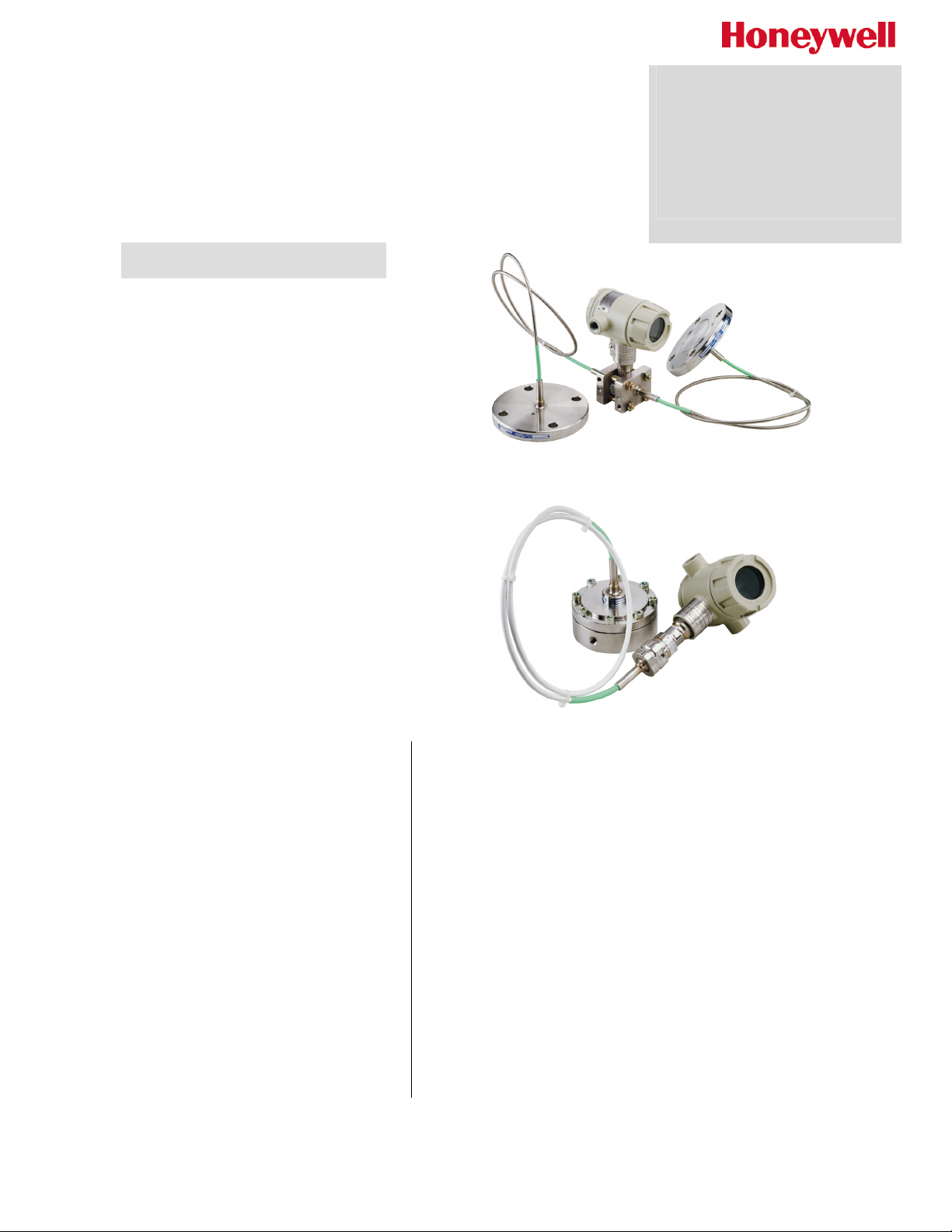
Figure 1—Series 100 Remote Seal Pressure Transmitters feature proven
piezoresistive sensors and advanced seal technology with standard weld
connections.
The devices provide comprehensive self-diagnostics to help users
maintain high uptime, meet regulatory requirements, and attain high
quality standards. S100 transmitters are ideal for critical applications,
such as custody transfer of natural gas and energy and material
balances, where accuracy and stability are of the utmost importance.
"Our commitment to Honeywell field instruments is based on
seamless integration with our Honeywell system and the enhanced
fault detection that the Honeywell DE protocol offers. Honeywell
instruments also offer us a better way of ensuring database integrity
over simple analog instruments. In addition, Honeywell's high-quality
support has enabled us to better implement solutions to some of our
more difficult problems. We have used Honeywell differential pressure
smart transmitters for the past eight years. Based on their accuracy
and low failure rates, we are now targeting critical flow applications
that require the robustness that these transmitters bring.”
DCS Systems Engineer
International Integrated Oil Company
• Lifetime Warranty = 15 years
34-ST-03-64
2/08
Specification and
Model Selection
Guide
Page 2
34-ST-03-64
Page 2
Description of Diaphragm Seals
Diaphragm seals are traditionally used when a standard pressure transmitter should not be exposed to the
process pressure directly. Diaphragm seals typically protect the pressure transmitter from one or more
damaging aspects of the process media. Consideration for using a diaphragm seal should be made in the
following circumstances.
• High Process Temperature
• Process Media is Viscous or Contains Suspended Solids
• Process Media is Subject to Solidifying
• Process Media is Corrosive
• Process Application Requires Sanitary Connections
• Process Application Subjects the Measuring Instrument to Hydrogen Permeation
• Tank Level Applications with Maintenance Intensive Wet Legs
• Tank Application with Density or Interface Measurements
• Measuring Instrument Requires Remote Mounting
The following diaphragm seals are standard from Honeywell (please call your local salesperson if you do not see
the product you need for your application):
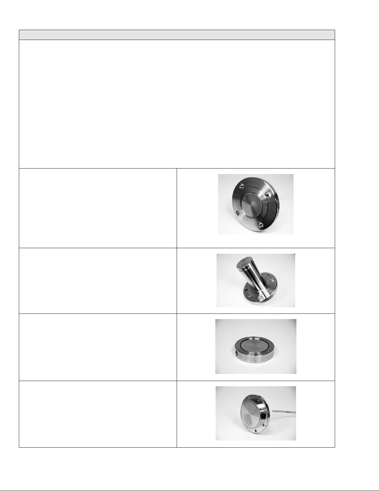
Figure 2 - Flush Flange Seals can be used with
differential, gauge and absolute pressure transmitters
and are available with 3” ANSI Class 150, ANSI Class
300 and DIN DN80-PN40 process connections. Flush
flange seals can also be provided with Lowers.
Lowers are essentially calibration rings, which allow
flushing connections if needed – see Figure 31.
Figure 2
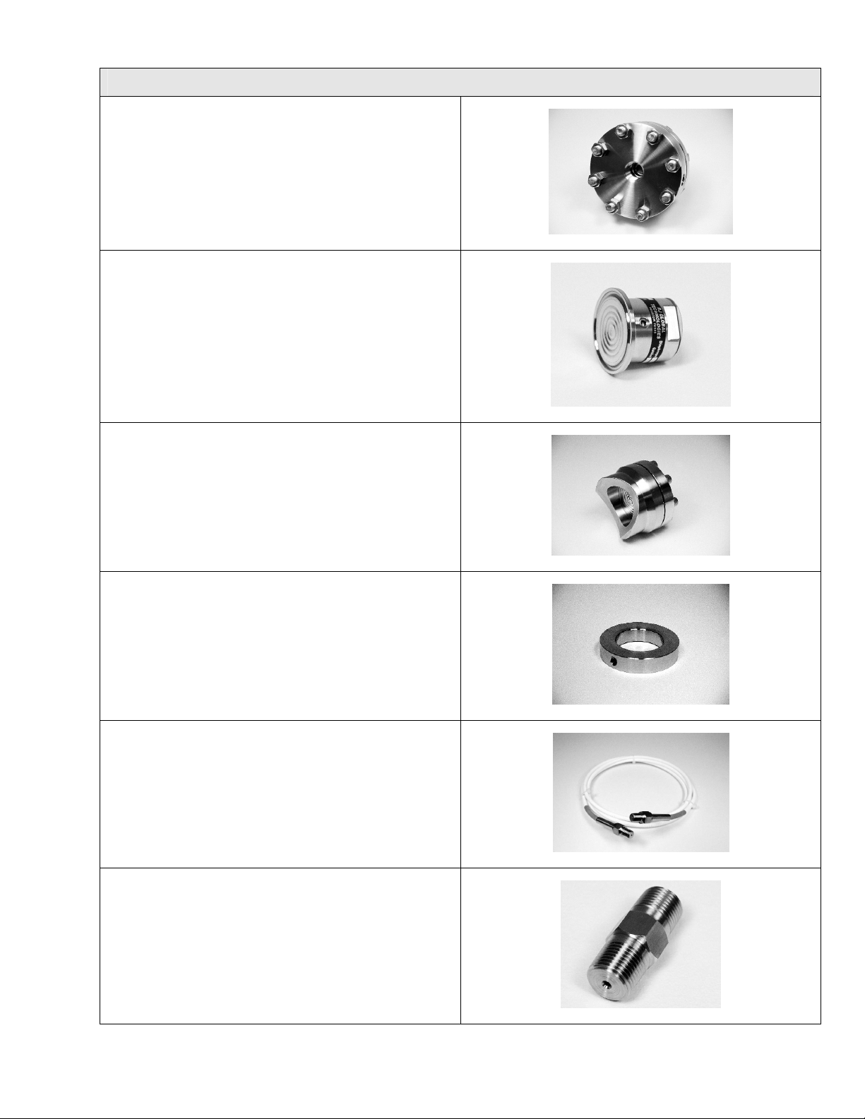
Figure 3 - Flange Seal with Extended Diaphragm
can be used with differential, gauge and absolute
pressure transmitters and are available with 3” and 4”
ANSI Class 150, ANSI Class 300, DIN DN80-PN40
and DIN DN100-PN40 process connections. 2”, 4” and
6” extension lengths are available.
Figure 3
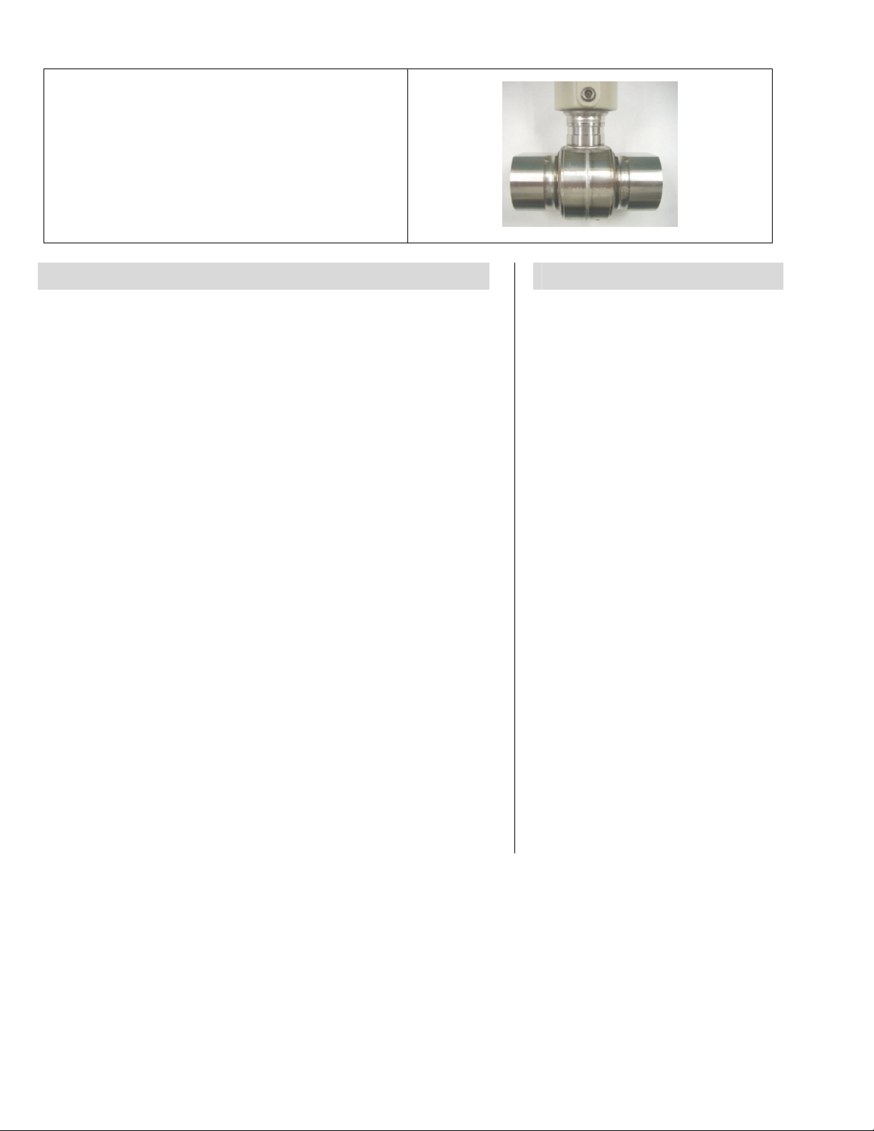
Figure 4 - Pancake Seals can be used with
differential, gauge and absolute pressure transmitters
and are available with 3” ANSI Class 150, 300 and 600
process connections.
Figure 4
Figure 5 - Chemical Tee “Taylor” Wedge seals can
be used with differential pressure transmitters and are
available with Taylor Wedge 5” O.D. process
connection.
Figure 5
Page 3
34-ST-03-64
Page 3
Description of Diaphragm Seals
Figure 6 - Seals with Threaded Process
Connections can be used with differential, gauge and
absolute pressure transmitters and are available with
½”, ¾” and 1” NPT Female process connections.
Figure 7 - Sanitary Seals can be used with
differential, gauge and absolute pressure transmitters
and are available with 3” and 4” Tri-Clover-Tri-Clamp
process connections.
Figure 8 - Saddle Seals can be used with differential,
gauge and absolute pressure transmitters and are
available with 3” and 4” (6 bolt or 8 bolt designs)
process connections.
Figure 9 - Calibration Rings are available with Flush
Flange Seals and Pancake Seals. Flushing ports (1/4”
or ½”) are available with calibration rings.
Figure 6
Figure 7
Figure 8
Figure 10 - Stainless Steel Armor and PVC Coated
Stainless Steel Armor Capillaries are available with
Honeywell Remote Seal Solutions.
Figure 11 - 2” Stainless Steel Nipples are available
for Close-Coupled remote seal solutions.
Figure 9
Figure 10
Figure 11
Page 4
34-ST-03-64
Page 4
Figure 12 - Welded Meter Body for All-Welded
Remote Seal Solution. The welded ST 3000 meter
body is an important part of an All-Welded Remote
Seal Solution, which is commonly used in Vacuum
applications.
Figure 12
Description Features
The ST 3000 transmitter can replace any 4 to 20 mA output
transmitter in use today and operates over a standard two-wire
system.
The measuring means is a piezoresistive sensor, which actually
contains three sensors in one. It contains a differential pressure
sensor, a temperature sensor, and a static pressure sensor.
Microprocessor-based electronics provide higher span-turndown
ratio, improved temperature and pressure compensation, and
improved accuracy.
The transmitter’s meter body and electronics housing resist shock,
vibration, corrosion, and moisture. The electronics housing contains
a compartment for the single-board electronics, which is isolated
from an integral junction box. The single-board electronics is
replaceable and interchangeable with any other ST 3000 Series 100
or Series 900 model transmitter.
Like other Honeywell transmitters, the ST 3000 features two-way
communication and configuration capability between the operator
and the transmitter through several Honeywell field-rated portable
configuration devices, including the Smart Field Communicator
(SFC) and the Multiple Communication Configurator (MC ToolKit).
While both are made for in-field use, the MC Toolkit also can be
ordered for use in intrinsically safe environments.
The SCT 3000 Smartline
way to configure instruments using a personal computer. The toolkit
enables configuration of devices before shipping or installation. The
SCT 3000 can operate in the offline mode to configure an unlimited
number of devices. The database can then be loaded down-line
during commissioning.
®
Configuration Toolkit provides an easy
• Choice of linear or square root
output conformity is a simple
configuration selection.
• Direct digital integration with
Experion PKS and other control
systems provides local
measurement accuracy to the
system level without adding
typical A/D and D/A converter
inaccuracies.
• Unique piezoresistive sensor
automatically compensates input
for temperature and static
pressure. Added “smart”
features include configuring
lower and upper range values,
simulating accurate analog
output, and selecting
preprogrammed engineering
units for display.
• Smart transmitter capabilities
with local or remote interfacing
means significant manpower
efficiency improvements in
commissioning, start-up, and
ongoing maintenance functions.
Page 5

34-ST-03-64
Page 5
Specifications
Operating Conditions – All Models
Parameter Reference Condition Rated Condition Operative Limits Transportation and
°C °F °C °F °C °F °C °F
Ambient Temperature * 25 ±1 77 ±2 — — — — –55 to 90 –67 to 194
Humidity % RH 10 to 55 0 to 100 0 to 100 0 to 100
Maximum Allowable
Working Pressure (MAWP)
Vacuum Region - Minimum
Pressure
mmHg absolute
Supply Voltage, Current,
and Load Resistance
* Ambient Temperature Limit is a function of Process Interface Temperature. (See Figure 13.)
MAWP is minimum of Body Rating or Seal Rating (See Model Selection Guide for Seal
MAWP)
Body MAWP
STR12D 2500 psig (172 bar) Bolted Process Heads Table I _ _ A
STR13D 2500 psig (172 bar) Bolted Process Heads Table I _ _ A
STR12D 1450 psig (100 bar) All Welded Process Heads Table I _ _ C
STR13D 1450 psig (100 bar) All Welded Process Heads Table I _ _ C
STR14G 500 psig (35 bar)
STR17G 3000psig (207 bar)
STR14A 500 psia (35 bar).
Atmospheric (See Figure 15 for vacuum limitations.)
Voltage Range: 10.8 to 42.4 Vdc at terminals
Current Range: 3.0 to 21.8 mA
Load Resistance: 0 to 1440 ohms (as shown in Figure 16)
Storage
Page 6

34-ST-03-64
Page 6
Performance Under Rated Conditions * - Model STR12D (0-10 to 0-400 inH2O)
Parameter Description
Upper Range Limit ** inH2O
mbar
Minimum Span inH2O
mbar
Turndown Ratio
Zero Elevation and Suppression
Accuracy (Reference – Includes
combined effects of linearity,
hysteresis, and repeatability)
• Accuracy includes residual error
after averaging successive
readings.
• For F
Combined Zero and Span
Temperature Effect per 28°C
(50°F) ***
OUNDATION Fieldbus use
Digital Mode specifications. For
HART use Analog Mode
specifications.
400 (39.2°F/4°C is standard reference temperature for inH2O range.)
1000
10 Note: Recommended minimum span in square root mode is 20 inH2O (50 mbar).
25
40 to 1
No limit except minimum span within ±100% URL.
In Analog Mode: ±0.2% of calibrated span or upper range value (URV), whichever is
greater, terminal based.
For URV below reference point (50 inH2O), accuracy equals:
50 inH2O
±0.1 + 0.1
In Digital Mode: ±0.175% of calibrated span or upper range value (URV), whichever is
greater, terminal based.
For URV below reference point (50 inH2O), accuracy equals:
±0.075 + 0.10
In Analog Mode: ±1.2% of span.
For URV below reference point (200 inH2O), effect equals:
±0.2 + 1.0
In Digital Mode: ±1.175% of span.
⎛
span inH2O
⎝
50 inH2O
⎛
span inH2O
⎝
200 in H
200 in H
200 in H2O
⎛
⎛
⎛
⎝
⎝
⎝⎛⎝
span in H
span in H
span in H
⎞
or ±0.1 + 0.1
⎠
⎞
or ±0.075 + 0.10
⎠
O
O
2
2
⎞
⎞
⎞
or ±0.2 + 1.0
or ±0.2 + 1.0
⎠
⎠
⎠⎞⎠
O
O
O
2
2
2
125 mbar
()
span mbar
500 mbar
500 mbar
500 mbar
⎛
⎛
⎛
⎝
⎝
⎝⎛⎝
span mbar
span mbar
span mbar
in % of span
125 mbar
()
span mbar
⎞
⎞
⎞
In % span±0.2 + 1.0
In % span
⎠
⎠
⎠⎞⎠
in % of span
For URV below reference point (200 inH2O), effect equals:
500 mbar
200 in H
200 in H
200 in H2O
⎛
⎛
±0.175 + 1.0
±0.175 + 1.0
* Performance specifications are based on reference conditions of 25°C (77°F), zero (0) static pressure, 10 to 55% RH, and
316L Stainless Steel barrier diaphragm.
** Transmitter URL limit or maximum seal pressure rating, whichever is lower.
*** Specification applies to transmitters with 2 seals only. Apply 1.5 times factor to temperature effect for capillary lengths greater than 10
feet.
⎛
⎝
⎝
⎝⎛⎝
span in H
span in H
span in H
O
O
2
2
⎞
⎞
⎞
or ±0.175 + 1.0
or ±0.175 + 1.0
⎠
⎠
⎠⎞⎠
O
O
O
2
2
2
500 mbar
500 mbar
⎛
⎛
⎛
⎝
⎝
⎝⎛⎝
span mbar
span mbar
span mbar
⎞
⎞
⎞
In % span
In % span
⎠
⎠
⎠⎞⎠
Page 7
34-ST-03-64
Page 7
Performance Under Rated Conditions * - Model STR13D (0-5 to 0-100 psid)
Parameter Description
Upper Range Limit ** psid
bar
Minimum Span psid
bar
Turndown Ratio
Zero Elevation and Suppression
Accuracy (Reference – Includes
combined effects of linearity,
hysteresis, and repeatability)
Stated accuracy does not apply
•
for models with 2.9 inch
diameter remote seal
diaphragms.
•
Accuracy includes residual error
after averaging successive
readings.
• For FOUNDATION Fieldbus use
Digital Mode specifications. For
HART use Analog Mode
specifications.
Combined Zero and Span
Temperature Effect per 28°C
(50°F) ***
100
7
5
0.35
20 to 1
No limit except minimum span within –18% and +100% of URL. Specifications valid from
–5% to 100% of URL.
In Analog Mode:
greater, terminal based.
For URV below reference point (30 psi), accuracy equals:
±0.05 + 0.05
In Digital Mode: ±0.075% of calibrated span or upper range value (URV), whichever is
greater, terminal based.
For URV below reference point (30 psi), accuracy equals:
±0.025 + 0.05
In Analog Mode:
For URV below reference point (60 psi), effect equals:
±0.05 + 0.2
±0.05 + 0.2
In Digital Mode: ±0.305% of span.
For URV below reference point (60 psi), effect equals:
±0.1% of calibrated span or upper range value (URV), whichever is
30 psi
()
span psi
30 psi
()
span psi
±0.33% of span.
60 psi
60 psi
⎛
⎛
⎝
⎝⎛⎝
span psi
span psi
or ±0.05 + 0.05
or ±0.025 + 0.05
⎞
⎞
or ±0.05 + 0.28
or ±0.05 + 0.28
⎠
⎠⎞⎠
2 bar
()
span bar
()
span bar
4 bar
4 bar
⎛
⎛
⎝
⎝⎛⎝
span bar
span bar
in % of span
2 bar
⎞
⎞
⎠
⎠⎞⎠
in % of span
In % span
In % span
60 psi
60 psi
⎛
±0.025 + 0.25
±0.025 + 0.25
* Performance specifications are based on reference conditions of 25°C (77°F), zero (0) static pressure, 10 to 55% RH, and
316L Stainless Steel barrier diaphragm.
** Transmitter URL limit or maximum seal pressure rating, whichever is lower.
*** Specification applies to transmitters with 2 seals only. Apply 1.5 times factor to temperature effect for capillary lengths greater than 10
feet.
⎛
⎝
⎝⎛⎝
span psi
span psi
⎞
⎞
or ±0.025 + 0.28
or ±0.025 + 0.28
⎠
⎠⎞⎠
4 bar
4 bar
⎛
⎛
⎝
⎝⎛⎝
span bar
span bar
⎞
⎞
In % span
In % span
⎠
⎠⎞⎠
Page 8
34-ST-03-64
Page 8
Performance Under Rated Conditions * - Model STR14G (0-5 to 0-500 psig)
Parameter Description
Upper Range Limit ** psig
bar
Minimum Span psig
bar
Turndown Ratio
Zero Elevation and Suppression
Accuracy (Reference – Includes
combined effects of linearity,
hysteresis, and repeatability)
Accuracy includes residual error
•
after averaging successive
readings.
• For FOUNDATION Fieldbus use
Digital Mode specifications. For
HART use Analog Mode
specifications.
* Performance specifications are based on reference conditions of 25°C (77°F), zero (0) static pressure, 10 to 55% RH, and
316L Stainless Steel barrier diaphragm.
** Transmitter URL limit or maximum seal pressure rating, whichever is lower.
500
35
5
0.35
100 to 1
No limit except minimum span from absolute zero to 100% of URL. Specifications valid
over this range.
In Analog Mode:
greater.
For URV below reference point (20 psi), accuracy equals:
±0.05 + 0.05
In Digital Mode: ±0.075% of calibrated span or upper range value (URV), whichever is
greater.
For URV below reference point (20 psi), accuracy equals:
±0.025 + 0.05
±0.1% of calibrated span or upper range value (URV), whichever is
20 psi
()
span psi
20 psi
()
span psi
or ±0.05 + 0.05
or ±0.025 + 0.05
1.4 bar
()
span bar
()
span bar
1.4 bar
in % of span
in % of span
Page 9
34-ST-03-64
Page 9
Performance Under Rated Conditions * - Model STR17G (0-100 to 0-3000 psig)
Parameter Description
Upper Range Limit ** psig
bar
Minimum Span psig
bar
Turndown Ratio
Zero Elevation and Suppression
Accuracy (Reference – Includes
combined effects of linearity,
hysteresis, and repeatability)
•
Accuracy includes residual error
after averaging successive
readings.
• For FOUNDATION Fieldbus use
Digital Mode specifications. For
HART use Analog Mode
specifications.
* Performance specifications are based on reference conditions of 25°C (77°F), zero (0) static pressure, 10 to 55% RH, and
316L Stainless Steel barrier diaphragm.
** Transmitter URL limit or maximum seal pressure rating, whichever is lower.
3000
210
100
7
30 to 1
No limit except minimum span from absolute zero to 100% of URL. Specifications valid
over this range.
In Analog Mode:
greater.
For URV below reference point (300 psi), accuracy equals:
±0.10 + 0.05
In Digital Mode: ±0.125% of calibrated span or upper range value (URV), whichever is
greater.
For URV below reference point (300 psi), accuracy equals:
±0.075 + 0.05
±0.15% of calibrated span or upper range value (URV), whichever is
300 psi
()
span psi
300 psi
()
span psi
or ±0.10 + 0.05
or ±0.075 + 0.05
21 bar
()
span bar
()
span bar
in % of span
21 bar
in % of span
Page 10
34-ST-03-64
Page 10
Performance Under Rated Conditions * - Model STR14A (0-5 to 0-500 psia)
Parameter Description
Upper Range Limit ** psia
bar absolute
Minimum Span psia
bar absolute
Turndown Ratio
Zero Elevation and Suppression
Accuracy (Reference – Includes
combined effects of linearity,
hysteresis, and repeatability)
•
Accuracy includes residual error
after averaging successive
readings.
• For FOUNDATION Fieldbus use
Digital Mode specifications. For
HART use Analog Mode
specifications.
* Performance specifications are based on reference conditions of 25°C (77°F), zero (0) static pressure, 10 to 55% RH, and
316L Stainless Steel barrier diaphragm.
** Transmitter URL limit or maximum seal pressure rating, whichever is lower.
500
35
5
0.35
100 to 1
No limit except minimum span from 0 to 100% URL.
In Analog Mode:
greater.
For URV below reference point (20 psi), accuracy equals:
±0.05 + 0.05
In Digital Mode: ±0.075% of calibrated span or upper range value (URV), whichever is
greater.
For URV below reference point (20 psi), accuracy equals:
±0.025 + 0.05
±0.1% of calibrated span or upper range value (URV), whichever is
20 psi
()
span psi
20 psi
()
span psi
or ±0.05 + 0.05
or ±0.025 + 0.05
1.4 bar
()
span bar
()
span bar
1.4 bar
in % of span
in % of span
Performance Under Rated Conditions – General for all Models
Parameter Description
Output (two-wire)
Supply Voltage Effect
Damping Time Constant
RFI Protection (Standard)
CE Conformity (Europe)
NAMUR NE 43 Compliance
Option
SIL 2/3 Compliance
Analog 4 to 20 mA or digital communications DE mode. Options available for
F
OUNDATION Fieldbus and HART protocol.
±0.005% of span per volt.
Adjustable from 0 to 32 seconds digital damping.
Negligible (20 to 1000 MHz at 30 volts per meter).
89/336/EEC, Electromagnetic Compatibility (EMC) Directive.
Transmitter failure information is generated when the measuring information is invalid or
no longer present. Failure information is transmitted as a current signal but outside the
normal 4-20 mA measurement signal level. Transmitter failure values are: ≤ 3.6 mA and
≥ 21.0 mA. The normal signal range is ≥ 3.8 mA and ≤ 20.5 mA.
SIL certified to IEC 61508 for non-redundant use in SIL 2 related Safety Systems
(single use) and for redundant (multiple) use in SIL 3 Safety Systems through
TÜV Nord Sys Tec GmbH & Co. KG under the following standards: IEC61508-1: 1998;
IEC 61508-2: 2000; IEC61508-3: 1998.
Page 11

34-ST-03-64
Page 11
Physical and Approval Bodies
Parameter Description
Process Interface
Seal Barrier Diaphragm
Seal Gasket Materials
Mounting Bracket
Fill Fluid (Meter Body)
See Model Selection Guide for Material Options for desired seal type.
316L Stainless Steel, Monel, Hastelloy C, Tantalum
Klinger C-4401 (non-asbestos) Grafoil Teflon Gylon 3510
Carbon Steel (Zinc-Chromate plated) or Stainless Steel.
Silicone (DC 200) S.G. @ 25°C = 0.94
CTFE (Chlorotrifluoroethylene) S.G. @ 25°C = 1.89
Fill Fluid (Secondary)
Silicone (DC 200) S.G. @ 25°C = 0.94
CTFE (Chlorotrifluoroethylene) S.G. @ 25°C = 1.89
Silicone (DC 704) S.G. @ 25°C = 1.07
NEOBEE M-20 S.G. @ 25°C = 0.90
Syltherm 800 S.G. @ 25°C = 0.93
Electronic Housing
Epoxy-Polyester hybrid paint. Low copper-aluminum alloy. Meets NEMA 4X (watertight)
and NEMA 7 (explosion proof). Stainless steel optional.
Capillary Tubing
Armored Stainless Steel or PVC Coated Armored Stainless Steel.
Length: 5, 10, 15, 20, 25, and 35 feet (1.5, 3, 4.6, 6.1, 7.5, and 10.7 meters).
A 2 inch (51 millimeter) S.S. close-coupled nipple is also available. See Model Selection
Guide. Refer to Figure 14 for guide to maximum capillary length vs. diaphragm diameter.
Wiring
Mounting
Accepts up to 16 AWG (1.5 mm diameter).
See Figure 17.
Dimensions Transmitter: See Figures 20a and 20b. Seal: See Figures 21 through 31.
Net Weight
Approval Bodies
Factory Mutual
CSA
Canadian Registration
Number (CRN)
ATEX
SA (Australian)
INMETRO (Brazil) Flame-Proof, Zone 1: EX d IIC T5
Transmitter:
15.4 pounds (7 Kg). Total weight is dependent on seal type and capillary
length.
Explosion Proof: Approved as Explosion Proof for Class I, Division 1, Groups A, B,
C, D locations,
Dust Ignition Proof: Approved as Dust Ignition Proof for Class II, III, Division 1,
Groups E, F, G locations,
Intrincically Safe: Approved as Intrinsically Safe for for Class I, II, III, Division 1,
Groups A, B, C, D, E, F, G locations.
Nonincendive: Approved as Nonincendive for Class I, Division 2, Groups A, B, C, D
locations.
Explosion Proof:
Approved as Explosion Proof for Class I, Division 1, Groups B, C,
D locations,
Dust Ignition Proof: Approved as Dust Ignition Proof for Class II, III, Division 1,
Groups E, F, G locations,
Intrincically Safe: Approved as Intrinsically Safe for Class I, II, III, Division 1, Groups
A, B, C, D, E, F, G locations.
All ST 3000 model designs, except SATG19L, STG99L, STG170 and STG180 have
been registered in all provinces and territories in Canada and are marked
CRN:0F8914.5c.
Intrinsically Safe, Zone 0/1: EEx ia IIC T4, T5, T6
Flameproof/Zone 1: EEx d IIC T5, T6 (enclosure IP 66/67)
Non-Sparking, Zone 2: EEx nA, IIC T6 (enclosure IP 66/67)
Multiple Markings:
Ex II 3 G
Intrinsically Safe:
Ex II 1 G: EEx ia IIC T4, T5, T6, Ex II 2 G: EExd IIC T5, T6
: EEx nA, IIC T6 (Honeywell) (enclosure IP 66/67)
EX ia IIC T4
Non-Sparking: Ex n IIC T6 (T4 with SM option)
Page 12
34-ST-03-64
Page 12
Parameter Description
Pressure Equipment Directive
(97/23/EC)
The ST 3000 pressure transmitters listed in this Specification have no pressurized
internal volume or have a pressurized internal volume rated less than 1,000 bar (14,500
psig) and/or have a maximum volume of less than 0.1 liter. Therefore, these
transmitters are either; not subject to the essential requirements of the directive
97/23/EC (PED, Annex 1) and shall not have the CE mark, or the manufacturer has the
free choice of a module when the CE mark is required for pressures > 200 bar (2,900
psig).
NOTE: Pressure transmitters that are part of safety equipment for the protection of piping (systems) or vessel(s) from
exceeding allowable pressure limits, (equipment with safety functions in accordance with Pressure Equipment Directive
97/23/EC article 1, 2.1.3), require separate examination.
200
Maximum Ambient
Maximum Ambient
Temperature (°F)
Temperature (°F)
200
180
180
160
160
140
140
120
120
100
100
80
80
60
60
40
40
20
20
0
0
185
185
200
200
Process Interface Temperature (°F)
Process Interface Temperature (°F)
165
165
350
350
140
140
450
450
Figure 13—Ambient temperature and process interface chart.
Transmitter Minimum Span and Maximum Capillary Length
Minimum recommended span for STR12D and STR13D DP Transmitter with two Remote Seals
Diaphragm Capillary Capillary Length
Size 5' 10' 15' 20' 30' 35' maximum
2.4 200 iwc - - - - - 5'
2.9 100 iwc 125 iwc 150 iwc 175 iwc - - 20'
3.5 16 iwc 20 iwc 24 iwc 28 iwc 36 iwc 40 iwc 35'
4.1 12 iwc 15 iwc 18 iwc 21 iwc 27 iwc 30 iwc 35'
Minimum recommended span for STR12D and STR13D DP Transmitter with one Remote Seal
Diaphragm Direct Capillary Capillary Length
Size Mount 5' 10' 15' 20' 30' 35' maximum
2.4 20 psig 30 psig - - - - - 5'
2.9 10 psig 15 psig 20 psig 25 psig 30 psig - - 20'
3.5 50 iwc 80 iwc 100 iwc 120 iwc 140 iwc 180 iwc 200 iwc 35'
4.1 40 iwc 60 iwc 80 iwc 100 iwc 120 iwc 160 iwc 180 iwc 35'
Minimum recommended span for STR14G, STR14A, STR17G Transmitter with Remote Seal
Diaphragm Direct Capillary Capillary Length
Size Mount 5' 10' 15' 20' 30' 35' maximum
2.0 25 psi 30 psi 40 psi 50 psi - - - 15'
2.4 10 psi 15 psi 20 psi 25 psi 30 psi 40 psi 50 psi 35'
2.9 8 psi 9 psi 10 psi 11 psi 12 psi 14 psi 15 psi 35'
3.5 5 psi 5 psi 5 psi 5 psi 5 psi 7 psi 8 psi 35'
4.1 5 psi 5 psi 5 psi 5 psi 5 psi 7 psi 8 psi 35'
Minimum span is the higher of the value from the table above or the value defined under Performance Conditions for the range transmitter
Figure 14—Maximum capillary length and diaphragm size chart.
Page 13
34-ST-03-64
Page 13
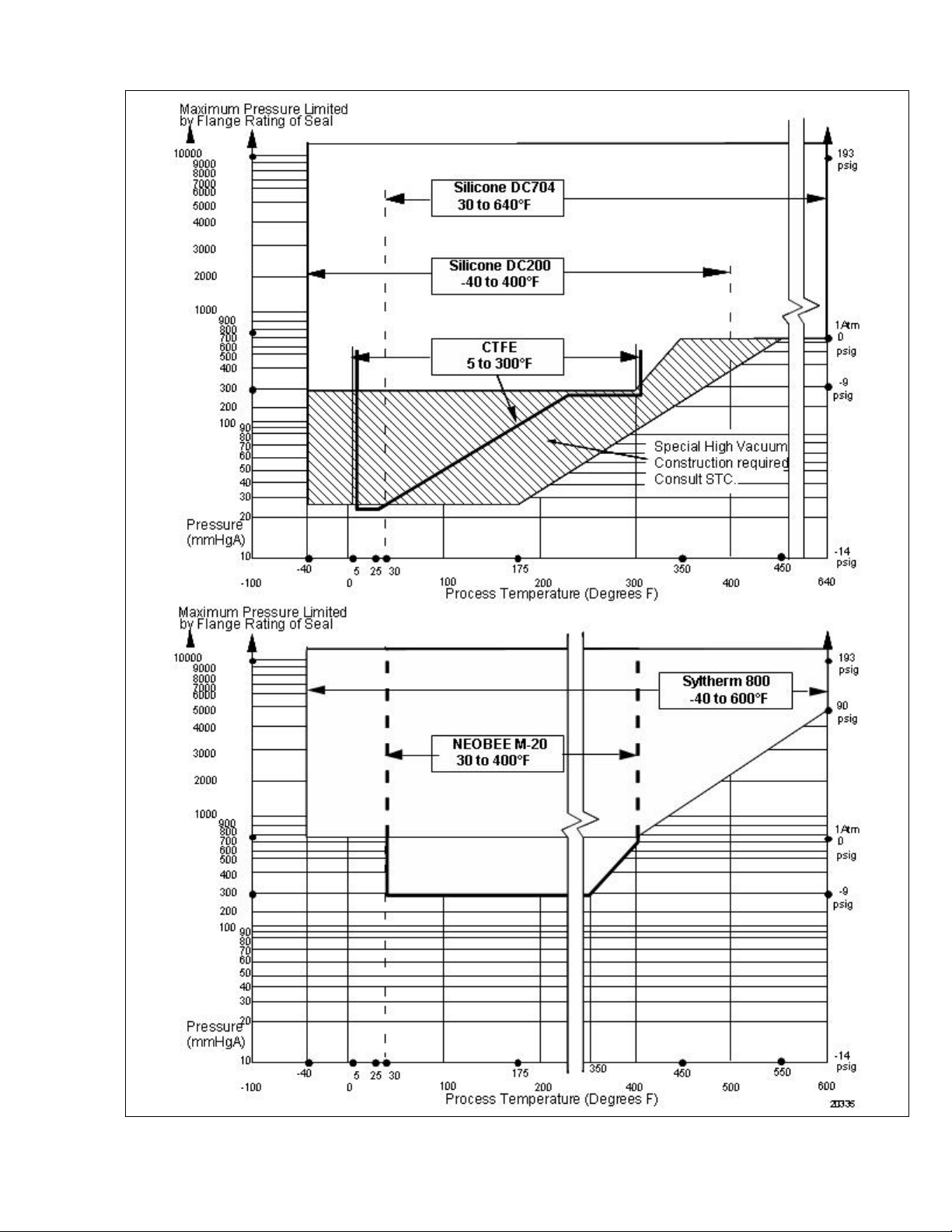
Figure 15—ST 3000 Remote Seals operable limits for pressure vs. temperature.
Page 14

34-ST-03-64
Page 14
1440
1440
1200
1200
Note: A minimum of 250 ohms
Loop
Loop
Resistance
Resistance
(ohms)
(ohms)
800
800
650
650
450
450
250
250
0 10.8 16.28 20.63 25 28.3 37.0 42.4
0 10.8 16.28 20.63 25 28.3 37.0 42.4
Operating Voltage (Vdc)
Operating Voltage (Vdc)
Note: A minimum of 250 ohms
of loop resistance is necessary
of loop resistance is necessary
to support communications.
to support communications.
Loop resistance equals barrier
Loop resistance equals barrier
resistance plus wire resistance
resistance plus wire resistance
plus receiver resistance.
plus receiver resistance.
= Operating Area
= Operating Area
Figure 16—Supply voltage/loop resistance chart.
LP Side
Maximum level
H2
Fixed
Minimum level
.
HP Side
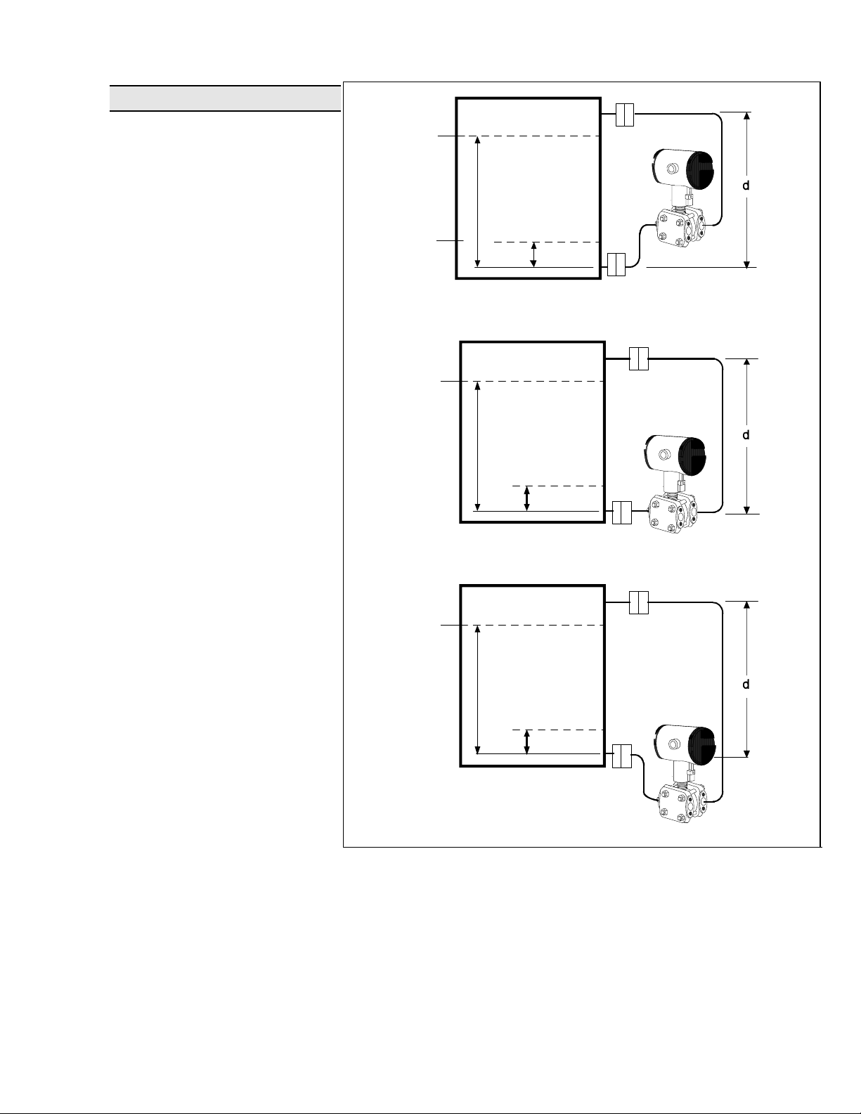
NOTE: Lower flange seal should not be mounted over 22 feet below or above
the transmitter for silicone fill fluid (11 feet for CTFE fill fluid) with tank at one
atmosphere. The combination of tank vacuum and high pressure capillary
head effect should not exceed 9 psi vacuum (300 mmHg absolute).
Consult Honeywell for installation of STR13D.
24249
Figure 17—The ST 3000 transmitter with remote diaphragm seals shown mounted on a tank.
Variableref. leg
Head
H1
Page 15
34-ST-03-64
Page 15
Application Data*
Liquid Level: Closed Tank
Max
Level
LP
Determine the minimum and
maximum pressure differentials to
be measured (Figure 18).
P
= (SGp x a) – (SGf x d)
Min
= LRV when HP at bottom
of tank
Min
Level
b
HP
a
= –URV when LP at
bottom of tank
Transmitter above datum
P
= (SGp x b) – (SGf x d)
Max
= URV when HP at bottom
of tank
= –LRV when LP at bottom
Max
Level
LP
of tank
Where:
Minimum level at 4 mA
Maximum level at 20 mA
a = distance between bottom
Min
Level
b
a
HP
tap and minimum level
Transmitter at datum
b = distance between bottom
tap and maximum level
d = distance between taps
SGf = Specific Gravity of capillary
Max
Level
LP
fill fluid (see page 11 for
values)
SGp = Specific Gravity of
process fluid
Min
Level
b
a
HP
* Contact STC-Phoenix concerning
applications for model STR13D.
Transmitter below datum
Figure 18—Closed tank liquid level measurement distances.
24253
Page 16

34-ST-03-64
Page 16
Density or Interface*
Calculate the minimum and
maximum pressure differentials to
be measured.
P
= (SG
min
minimum density, 4mA
output
P
= (SG
max
maximum density, 20mA
output
Where:
d = distance between the
SG
SG
SGf = Specific Gravity of
= maximum Specific
max
= minimum Specific
min
- SGf) x (d);
min
- SGf) x (d);
max
taps
Gravity
Gravity
capillary fill fluid (see
page 11 for values)
* Contact STC-Phoenix concerning
applications for model STR13D.
Figure 19—Density, direct acting instrument configuration.
LP
HP
24257
Page 17

34-ST-03-64
Page 17
With Smart meter
Removal
Clearance
for All Caps
45.7
1.8
82.9
3.26
53.1
2.09
Without
meter
94.9
3.74
65.1
2.56
Without
meter
With Analog
meter
23.5
.925
Reference
Dimensions:
millimeters
inches
55.3
2.18
135
5.32
3.6
0.14
Plug
Optional
meters
With Smart meter
Removal
Clearance
for All Caps
45.7
1.8
82.9
3.26
53.1
2.09
Without
meter
94.9
3.74
65.1
2.56
Without
meter
71.1
2.80
Optional external
ground
With Analog meter
23.5
.925
Optional external
ground
Seal
omitted
for clarity
SQ.
STR12D, STR13D
DP/I Remote Seal
with Horizontal
Pipe Mount
STR14A
AP/I Remote Seal
with Horizontal
Pipe Mount
85
3.35
55.3
2.18
42.5
1.67
135
5.32
50
1.97
Rotational
lock
LP seal
omitted for
clarity
3.6
Plug
0.14
Optional
meters
Rotational
lock
With Smart meter
Removal
Clearance
for All Caps
45.7
1.8
82.9
3.26
Without
meter
53.1
2.09
94.9
3.74
65.1
2.56
Without
meter
With Analog meter
23.5
.925
Optional external
ground
Seal
omitted
for clarity
STR14G, STR17G
LGP/I Remote Seal
with Horizontal
Pipe Mount
55.3
2.18
135
5.32
Figure 20a —Approximate horizontal mounting dimensions for Remote Seal Transmitter.
3.6
Plug
0.14
Optional
meters
Rotational
lock
24261
Page 18

34-ST-03-64
Page 18
Reference
Dimensions:
millimeters
inches
55.3
2.18
135
5.32
3.6
0.14
Plug
Optional
meters
Rotational
lock
LP seal
omitted
for clarity
With Smart meter
Removal
Clearance
for All Caps
45.7
1.8
82.9
3.26
53.1
2.09
Without
meter
94.9
3.74
65.1
2.56
Without
meter
With Analog
meter
23.5
.925
Optional external
ground
With Smart meter
Removal
Clearance
for All Caps
45.7
1.8
82.9
3.26
53.1
2.09
Without
meter
94.9
3.74
65.1
2.56
Without
meter
With Analog
meter
23.5
.925
Optional external
ground
71.1
SQ.
2.80
STR12D, STR13D
DP/I Remote Seal
with Vertical
Pipe Mount
STR14A
AP/I Remote Seal
with Vertical
Pipe Mount
Seal
omitted
for clarity
85
3.35
SQ
55.3
2.18
42.5
1.67
50
1.97
135
5.32
3.6
Plug
0.14
Optional
meters
Rotational
lock
With Smart meter
Removal
Clearance
for All Caps
45.7
1.8
82.9
3.26
Without
meter
53.1
2.09
94.9
3.74
65.1
2.56
Without
meter
With Analog
meter
23.5
.925
Optional external
ground
Seal
omitted
for clarity
STR14G, STR17G
LGP/I Remote Seal
with Vertical Pipe
Mount (Flat Bracket)
55.3
2.18
135
5.32
3.6
Plug
0.14
Optional
meters
Rotational
lock
24262
Figure 20b —Approximate vertical mounting dimensions for Remote Seal Transmitter.
Page 19

34-ST-03-64
Page 19
Options Ordering Information
Mounting Bracket
The angle mounting bracket is
available in either zinc-plated
carbon steel or stainless steel and
is suitable for horizontal or vertical
mounting on a two inch (50
millimeter) pipe, as well as wall
mounting. An optional flat
mounting bracket is also available
in carbon steel for two inch (50
millimeter) pipe mounting.
Indicating Meter
(Options ME and SM)
Two integral meter options are
available. An analog meter (option
ME) is available with a 0 to 100%
linear scale. The Smart Meter
(option SM) provides an LCD
display for both analog and digital
output and can be configured to
display pressure in pre-selected
engineering units.
®
HART
Protocol Compatibility
(Options HC and H6)
Optional electronics modules for
the ST 3000 provides HART
Protocol compatibility in either
HART 5.x or 6.x formats.
Transmitters with a HART Option
are compatible with any HART
enabled system that provides 5.x
or 6.x format support.
FOUNDATION Fieldbus
(Option FF)
Equips transmitter with FF
protocol for use in 31.25 kbit/s FF
networks. See document 34-ST03-72 for additional information on
ST 3000 Fieldbus transmitters.
SIL2/SIL3 Certification
(Option SL)
This ST 3000 product is available
for use with safety systems. With
the SL option, we are fully certified
to SIL 2 capability for single
transmitters and SIL 3 capability for
multiple transmitter use through
TÜV Nord Sys Tec GmbH & Co.
KG. We are in compliance with the
following SIL standards:
IEC 61508-1: 1998;
IEC 61508-2: 2000;
IEC 61508-3: 1998
NAMUR NE43 Compliance
(Option NE)
This option provides software the
meets the NAMUR NE43
requirements for failsafe software.
Transmitter failure information is
generated when the measuring
information is no longer valid.
Transmitter failure values are:
≤ 3.6 mA and ≥ 21.0 mA. The
normal ST 3000 ranges are ≤ 3.8
mA and ≥ 20.5 mA.
Lightning Protection
(Option LP)
A terminal block with circuitry that
protects the transmitter from
transient surges induced by
nearby lightning strikes is
available.
Indicator Configuration
(Option CI)
Provides custom configuration of
Smart Meters
Tagging (Option TG)
Up to 30 characters can be added
on the stainless steel nameplate
mounted on the transmitter’s
electronics housing at no extra
cost. Note that a separate
nameplate on the meter body
contains the serial number and
body-related data. A stainless
steel wired on tag with additional
data of up to 4 lines of 28
characters is also available. The
number of characters for tagging
includes spaces.
Transmitter Configuration
(Option TC)
The factory can configure the
transmitter linear/square root
extraction, damping time, LRV,
URV and mode (analog/digital) and
enter an ID tag of up to eight
characters and scratchpad
information as specified.
Custom Calibration and ID in
Memory (Option CC)
The factory can calibrate any range
within the scope of the transmitter’s
range and enter an ID tag of up to
eight characters in the transmitter’s
memory.
Contact your nearest Honeywell sales
office, or
In the U.S.:
Industrial Automation & Control
16404 North Black Canyon Hwy.
Phoenix, AZ 85053
1-800-288-7491
In Canada:
The Honeywell Centre
155 Gordon Baker Rd.
North York, Ontario M2H 3N7
1-800-461-0013
In Latin America:
480 Sawgrass Corporate Parkway,
Sunrise, FL 33325
(954) 845-2600
In Europe and Africa:
Honeywell S. A.
Avenue du Bourget 1
1140 Brussels, Belgium
In Eastern Europe:
Honeywell Praha,
s.r.o. Budejovicka 1
140 21 Prague 4,
Czech Republic
In the Middle East:
Honeywell Middle East Ltd.
Sheikh Faisal Building
Abu Dhabi, U. A. E.
In Asia:
Honeywell Asia Pacific Inc.
Honeywell Building,
17 Changi Business Park Central 1
Singapore 486073
Republic of Singapore
In the Pacific:
Honeywell Pty Ltd.
5 Thomas Holt Drive
North Ryde NSW Australia 2113
(61 2) 9353 7000
In Japan:
Honeywell K.K.
14-6 Shibaura 1-chrome
Minato-ku, Tokyo, Japan 105-0023
Or, visit Honeywell on the World Wide
Web at:
Specifications are subject to change
http://www.honeywell.com
Honeywell
Honeywell Inc.
Suite 200
Khalifa Street,
without notice
Page 20

34-ST-03-64
_
_ _
_ _
_ _
_
_
_
_
_ _
_ _
y
_ _
_ _
y
_ _
_ _
_ _
y
y
Page 20
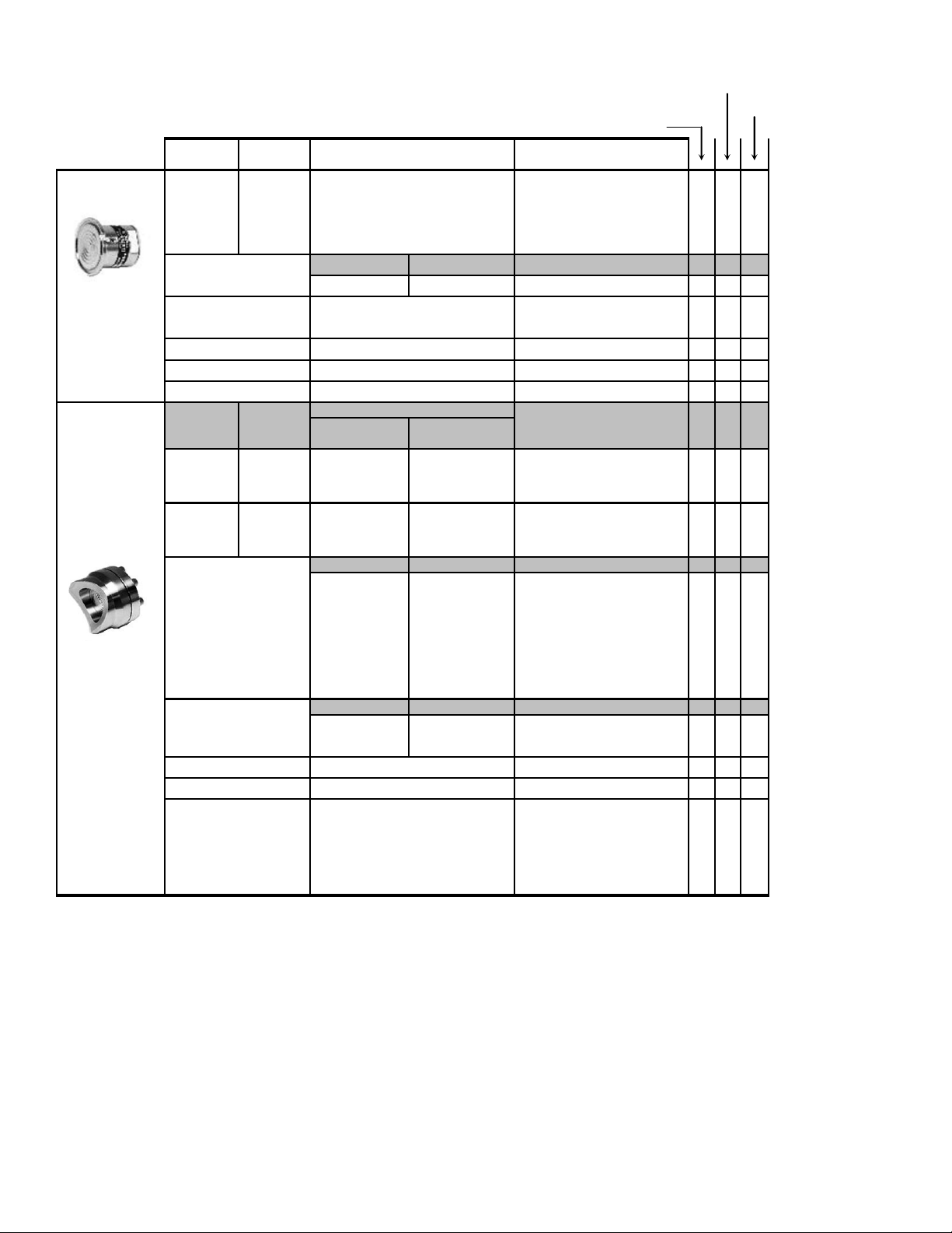
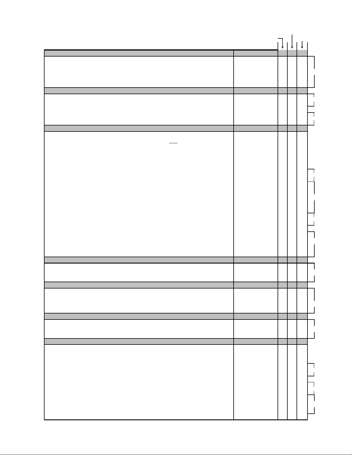
Model Selection Guide (34-ST-16-32)
Model Selection Guide
34-ST-16-32 Issue 39
Instructions
Select the desired Key Number. The arrow to the right marks the selection available.
●
Make one selection from each Table I and II using the column below the proper arrow.
●
Select as many Table III options as desired (if no options or approvals are desired, specify 9X).
●
A (●) denotes unrestricted availability. A letter denotes restricted availability.
●
Restrictions follow Table IV.
●
Key Number
_ _ _ _ _ _ _ _ , _ __ _ _ _ _ _ _ _ _ _ _ _
KEY NUMBER
0-10" to 0-400" H
Body Rating*: 2,500 psi (172 bar) Compound Characterized
0-5 to 0-100 psi/0-0.34 to 0-7 bar
Body Rating*: 2,500 psi (172 bar)
0-5 to 0-500 psia/0-0.34 to 0-35 bar
Body Rating*: 500 psi (35 bar)
0-5 to 0-500 psi/0-0.34 bar to 0-35 bar
Body Rating*: 500 psi (35 bar)
0-100 to 0-3,000 psi/0-7 bar to 210 bar
Body Rating*: 3,000 psi (210 bar)
* Remote seal system pressure rating is body rating or seal rating, whichever is less.
Important Note:
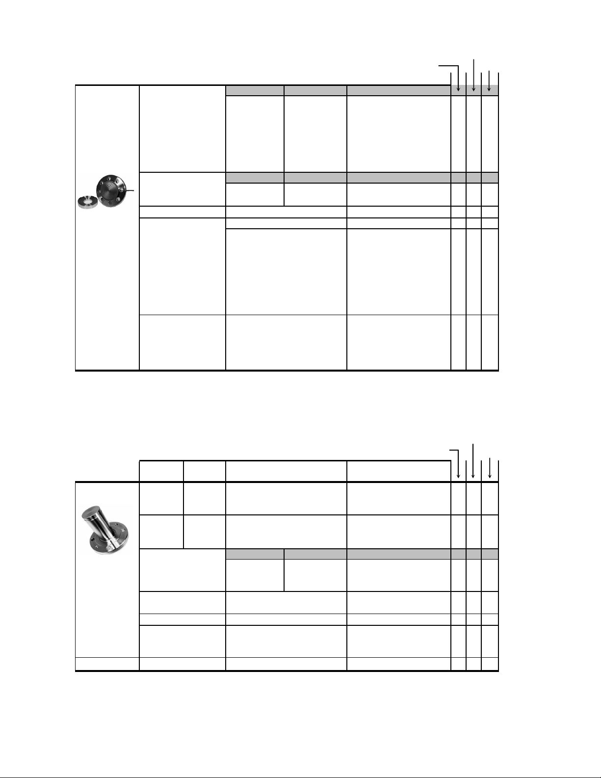
TABLE I - METER BODY
Number of Seals
Fill Fluid
(Meter body)
Construction
In-Line Gauge
Dual Head DP
Single Head
Absolute
O/0-25 to 0-1,000 mbar
2
I
_ _ _
-- - +
Description
Base STR models no longer include a default communications option. All units now require the
selection of a communication option from Table III (AN, DE, HC, H6 or FF).
1 Remote Seal (High Side)
2 Remote Seals
1 Remote Seal (Low Side)
Value Added Model (VAM unit)
Silicone (DC 200)
CTFE
Non-Wetted Adapter Head Material
316 SS Bonnet
316 SS Bonnet for Close-Couple
316 SS (bolt-on heads)
316 SS for Close-Couple
316 SS with all-welded meter body
316 SS Adapter Head
316 SS Head for Close-Couple
III (Optional)
Selection
STR12D
STR13D
STR14A
STR14G
STR17G
Selection
1 _
2
3
5
XXXX
1
2
A
D
A
D
C
A
D
IV II
Availabilit
●● ●
●
●
888
●● ●
qqq
●
●
7
●
In-Line Gauge All welded
Dual Head DP
Page 21

34-ST-03-64
g
y
Page 21
TABLE II - SEALS
Format for Seal Selection:
Specify 12 characters _ _ _ _ _ _ _ _ _ _ _ _
Common Required Seal
12D & 13D 14G&17G
14A
Note: The first 3 characters are common to all seals.
When selectin
only the 9 selections within the required seal.
Secondary Fill
required seal, you must specif
No Fill Fluid
Silicone (DC 200)
CTFE
Silicone (DC 704)
Neobee(M20) **
Syltherm 800
***
No Capillary, No Nipple
Selection
0 _ _ _ _ _ _ _ _ _ _ _ 333
1 _ _ _ _ _ _ _ _ _ _ _ ●● ●
2 _ _ _ _ _ _ _ _ _ _ _ ●● ●
3 _ _ _ _ _ _ _ _ _ _ _
4 _ _ _ _ _ _ _ _ _ _ _
●● ●
●● ●
5 _ _ _ _ _ _ _ _ _ _ _ ●● ●
_ 0 _ _ _ _ _ _ _ _ _ _
333
5 feet 1.5 m _ A _ _ _ _ _ _ _ _ _ _ ●● ●
10 feet 3.0 m _ B _ _ _ _ _ _ _ _ _ _ ●● ●
Connection of
Remote Seal to
Meter Body
Capillary
Length
15 feet 4.5 m _ C _ _ _ _ _ _ _ _ _ _ ●● ●
20 feet 6.1 m _ D _ _ _ _ _ _ _ _ _ _
25 feet 7.5 m _ E _ _ _ _ _ _ _ _ _ _
35 feet 10.7 m _ F _ _ _ _ _ _ _ _ _ _ ●● ●
5 feet 1.5 m _ G _ _ _ _ _ _ _ _ _ _
10 feet 3.0 m _ H _ _ _ _ _ _ _ _ _ _ ●● ●
15 feet 4.5 m _ J _ _ _ _ _ _ _ _ _ _ ●● ●
20 feet 6.1 m _ K _ _ _ _ _ _ _ _ _ _ ●● ●
25 feet 7.5 m _ L _ _ _ _ _ _ _ _ _ _
SS Armor
PVC Coated SS
Armor
●● ●
●● ●
●● ●
●● ●
35 feet 10.7 m _ M _ _ _ _ _ _ _ _ _ _ ●● ●
2 inch long SS nipple close-coupled
No Selection
No Seal Attached to Core Transmitter
Diaphragm
Diameter
3.5"
Flange
Size
3"
Wetted Material
Flush Flanged
Seal
Non-Wetted Material
(upper)
Seal-Capillary
Connection
Calibration Rings
Flange Pressure
Rating *
ANSI Class 150
ANSI Class 300
DIN DN80-PN40
316L SS
Hastelloy C
Hastelloy C
Tantalum
CS (Nickel Plated)
316 SS
Center Seal
Side Seal
None
316 SS
Hastelloy C
Monel
316 SS
316 SS
Hastelloy C
MonelMonel
316 SS
_ 2 _ _ _ _ _ _ _ _ _ _
_ _ 0 _ _ _ _ _ _ _ _ _
_ _ _ 0 0 0 0 0 0 0 0 0
Selection
_ _ _ AFA _ _ _ _ _ _
_ _ _ AFC _ _ _ _ _ _
_ _ _ AFM _ _ _ _ _ _
SelectionDiaphragm Upper Insert
_ _ _ _ _ _ AA _ _ _ _
_ _ _ _ _ _ AB _ _ _ _
_ _ _ _ _ _ AC _ _ _ _
_ _ _ _ _ _ AE _ _ _ _ ●●●
_ _ _ _ _ _ AF _ _ _ _
_ _ _ _ _ _ _ _ 1 _ _ _ ●● ●
_ _ _ _ _ _ _ _ 2 _ _ _ ●● ●
_ _ _ _ _ _ _ _ _ 1 _ _ ●● ●
_ _ _ _ _ _ _ _ _ 2 _ _
_ _ _ _ _ _ _ _ _ _ A _
_ _ _ _ _ _ _ _ _ _ B _ 55 5
_ _ _ _ _ _ _ _ _ _ C _
_ _ _ _ _ _ _ _ _ _ D _ 55 5
zzz
●● ●
333
●● ●
●● ●
●● ●
●● ●
●● ●
●● ●
111
999
●● ●
555
Table II continued next page
Page 22

34-ST-03-64
A
Page 22
STR14
STR12D & 13D 14G & 17G
TABLE II - SEALS (continued)
Flush Flanged
Seal
Standard facing 125-250 AARH RF (raised face) serrated surface finish.
*
Limited vacuum availability.
**
Minimum static pressure requirement. No vacuum allowed. See Specifications Figure 15.
***
Plastic Plugs are TEMPORARY ONLY to protect threads and MUST be REMOVED before installation
****
a
Tantalum Upper insert has Tantalum wetted parts and 316 SS or CS non-wetted parts
Note:
Remote seal system pressure rating is body rating or seal rating, whichever is less.
TABLE II - SEALS (continued)
Flush Flanged
Seal with Lower
*
Standard facing 125-250 AARH RF (raised face) serrated finish.
**
Plastic Plugs are TEMPORARY ONLY to protect threads and MUST be REMOVED before installation
Note:
Remote seal system pressure rating is body rating or seal rating, whichever is less.
Flushing
Connections
and Plugs****
(Metal plug material _ _ _ _ _ _ _ _ _ _ _ M 66 6
will be the same as _ _ _ _ _ _ _ _ _ _ _ N 66 6
Cal. ring material if _ _ _ _ _ _ _ _ _ _ _ P
metal plug is chosen - _ _ _ _ _ _ _ _ _ _ _ Q
SS Plug for CS Lower)
Diaphragm
Diameter
2.4"
2.9"
4.1"
Flange
Size
1"
1-1/2"
2"
3"
1/2" ANSI 150 23 _ _ _ CAA _ _ _ _ _ _
1"
1-1/2"
2"
1/2" ANSI 150 22 _ _ _ DAA _ _ _ _ _ _
1"
1-1/2"
2"
3"
One 1/4" with plastic plug
One 1/4" with metal plug
Two 1/4" with plastic plugs
Two 1/4" with metal plugs
One 1/2" with plastic plug
One 1/2" with metal plug
Two 1/2" with plastic plugs
Two 1/2" with metal plugs
Flange
Pressure
Rating *
ANSI 150 22 _ _ _ BCA _ _ _ _ _ _
ANSI 300 22 _ _ _ BCC _ _ _ _ _ _
ANSI 150 22 _ _ _ BGA _ _ _ _ _ _
ANSI 300 22 _ _ _ BGC _ _ _ _ _ _
ANSI 150 22 _ _ _ BDA _ _ _ _ _ _ t4●
ANSI 300 22 _ _ _ BDC _ _ _ _ _ _ t4●
ANSI 150 22 _ _ _ BFA _ _ _ _ _ _ t4●
ANSI 300 22 _ _ _ BFC _ _ _ _ _ _
ANSI 150 23 _ _ _ CCA _ _ _ _ _ _
ANSI 300 23 _ _ _ CCC _ _ _ _ _ _
ANSI 150 22 _ _ _ CGA _ _ _ _ _ _
ANSI 300 22 _ _ _ CGC _ _ _ _ _ _ ●● ●
ANSI 150 22 _ _ _ CDA _ _ _ _ _ _ ●●●
ANSI 300 22 _ _ _ CDC _ _ _ _ _ _ ●● ●
ANSI 150 23 _ _ _ DCA _ _ _ _ _ _
ANSI 300 23 _ _ _ DCC _ _ _ _ _ _
ANSI 150 23 _ _ _ DGA _ _ _ _ _ _
ANSI 300 23 _ _ _ DGC _ _ _ _ _ _
ANSI 150 23 _ _ _ DDA _ _ _ _ _ _ ●●●
ANSI 300 22 _ _ _ DDC _ _ _ _ _ _ ●● ●
ANSI 150 22 _ _ _ DFA _ _ _ _ _ _ ●● ●
ANSI 300 22 _ _ _ DFC _ _ _ _ _ _
None
Const. - See
Spec. Figure 34-
ST-03-64
_ _ _ _ _ _ _ _ _ _ _ 0
_ _ _ _ _ _ _ _ _ _ _ H
_ _ _ _ _ _ _ _ _ _ _ J
_ _ _ _ _ _ _ _ _ _ _ R
_ _ _ _ _ _ _ _ _ _ _ S
Construction - See Spec.
Figure 34-ST-03-64
Selection
●● ●
666
666
666
666
666
666
Table II continued below
STR12D & 13D STR14A
14G & 17G
Selection
t4●
t4●
t4●
t4●
t4●
●● ●
●● ●
●● ●
●● ●
●● ●
●● ●
●● ●
●● ●
●● ●
●● ●
Table II continued next page
Page 23
34-ST-03-64
Page 23
STR14A
STR12D & 13D 14G & 17G
TABLE II - SEALS (continued)
Diaphragm Lower
Flush Flanged
Seal with Lower
316L SS
Hastelloy C
Wetted Material
Hastelloy C
Monel
Tantalum
Tantalum
Tantalum
Non-Wetted Material
(upper, upper insert)
Bolts***
Upper Upper Insert
316 SS
Carbon Steel
No Selection
Flushing _ _ _ _ _ _ _ _ _ _ 0 _ ●● ●
Connections _ _ _ _ _ _ _ _ _ _ H _
and Plugs** _ _ _ _ _ _ _ _ _ _ J _
(Metal plug material
will be the same as
Lower material, if
metal plug is chosen (SS Plug for CS Lower
and Tantalum Clad)
One 1/4" with plastic plug
One 1/4" with metal plug
Two 1/4" with plastic plugs
Two 1/4" with metal plugs
One 1/2" with plastic plug
One 1/2" with metal plug
Two 1/2" with plastic plugs
Two 1/2" with metal plugs
316 SS
316 SS
Hastelloy C
Monel
316 SS
Hastelloy C
Tantalum Clad
316 SS
316 SS
None
Klinger C-4401
(non-asbestos)
Gasket
Grafoil
Teflon
Gylon 3510
Standard facing 125-250 AARH RF (raised face) serrated finish.
*
Plastic Plugs are TEMPORARY ONLY to protect threads and MUST be REMOVED before installation
**
Bolt material will be same as Upper Material. However, if Table III bolt/nut option is chosen, seal bolt material will be the same.
***
Note:
Remote seal system pressure rating is body rating or seal rating, whichever is less.
Selection
_ _ _ _ _ _ BA _ _ _ _ ●●●
_ _ _ _ _ _ BB _ _ _ _
●● ●
_ _ _ _ _ _ BC _ _ _ _ ●● ●
_ _ _ _ _ _ BE _ _ _ _
_ _ _ _ _ _ BF _ _ _ _
●● ●
111
_ _ _ _ _ _ BG _ _ _ _ 111
_ _ _ _ _ _ BH _ _ _ _
10 10 10
Selection
_ _ _ _ _ _ _ _ 4 _ _ _ ●● ●
_ _ _ _ _ _ _ _ 5 _ _ _ ●● ●
_ _ _ _ _ _ _ _ _ 0 _ _
●● ●
●● ●
●● ●
_ _ _ _ _ _ _ _ _ _ M _
_ _ _ _ _ _ _ _ _ _ N _
●● ●
●● ●
_ _ _ _ _ _ _ _ _ _ P _ ●● ●
_ _ _ _ _ _ _ _ _ _ Q _
●● ●
_ _ _ _ _ _ _ _ _ _ R _ ●● ●
_ _ _ _ _ _ _ _ _ _ S _
_ _ _ _ _ _ _ _ _ _ _ K
_ _ _ _ _ _ _ _ _ _ _ G
●● ●
ccc
● ● ●
_ _ _ _ _ _ _ _ _ _ _ T ccc
_ _ _ _ _ _ _ _ _ _ _ L
ddd
Table II continued below
TABLE II - SEALS (continued)
Flange
Size
3" _ _ _ EFA _ _ _ _ _ _
(2.8" OD
extension)
4" _ _ _ FGA _ _ _ _ _ _
(3.70" OD
extension
Flange Pressure Rating *
ANSI Class 150
ANSI Class 300
DIN DN80-PN40
ANSI Class 150
ANSI Class 300
DIN DN100-PN40
Diaphragm Ext. Tube
316L SS
Hastelloy C 316 SS
Hastelloy C
CS (Nickel Plated)
316 SS
Bolts
No Selection
Flange Seal
with Extended
Diaphragm
Diaphragm
Diameter
2.8"
3.5"
Wetted Material
Non-Wetted
Material (flange)
2"
Extension Length 4"
6"
No Selection No Selection No Selection
316 SS
Hastelloy C
STR14A
STR12D & 13D 14G & 17G
Selection
●● ●
_ _ _ EFC _ _ _ _ _ _
_ _ _ EFM _ _ _ _ _ _
●● ●
●● ●
●● ●
_ _ _ FGC _ _ _ _ _ _
_ _ _ FGP _ _ _ _ _ _
●● ●
●● ●
Selection
_ _ _ _ _ _ EA _ _ _ _
_ _ _ _ _ _ EB _ _ _ _
_ _ _ _ _ _ EC _ _ _ _
_ _ _ _ _ _ _ _ 7 _ _ _
_ _ _ _ _ _ _ _ 8 _ _ _
_ _ _ _ _ _ _ _ _ 0 _ _
_ _ _ _ _ _ _ _ _ _ 2 _
_ _ _ _ _ _ _ _ _ _ 4 _
●● ●
●● ●
●● ●
●● ●
●● ●
●● ●
●● ●
●● ●
_ _ _ _ _ _ _ _ _ _ 6 _ ●● ●
_ _ _ _ _ _ _ _ _ _ _ 0 ●● ●
Table II continued next page
Page 24

34-ST-03-64
Page 24
STR14A
TABLE II - SEALS (continued)
Diaphragm
Diameter
Flange
Size
Flange Pressure Rating
Dependent on Customer Flange
STR12D & 13D 14G & 17G
Selection
3.5" 3" _ _ _ GFA _ _ _ _ _ _
Wetted Material
Non-Wetted Material No Selection
Bolts
Calibration Rings
Pancake Seal
Connections
and Plugs***
(Metal plug material
will be the same as
Cal. Ring material, if
metal plug is chosen SS Plug for CS Lower)
Standard facing 125-250 AARH RF (raised face) serrated finish.
*
Plastic Plugs are TEMPORARY ONLY to protect threads and MUST be REMOVED before installation
***
Tantalum Body has Tantalum wetted parts and 316 SS non-wetted parts
a
Note:
Remote seal system pressure rating is body rating or seal rating, whichever is less.
ANSI Class 150/300/600
Diaphragm Body
316L SS
Hastelloy C
Hastelloy C
Monel
Tantalum
No Selection
Hastelloy C
One 1/4" with plastic plug
One 1/4" with metal plug
Two 1/4" with plastic plugs
Two 1/4" with metal plugs
One 1/2" with plastic plug
One 1/2" with metal plug
Two 1/2" with plastic plugs
Two 1/2" with metal plugs
316 SS
316 SS
Hastelloy C
Monel
Tantalum
None
316 SS
Monel
NoneFlushing
_ _ _ _ _ _ GA _ _ _ _
_ _ _ _ _ _ GB _ _ _ _
_ _ _ _ _ _ GC _ _ _ _
_ _ _ _ _ _ GE _ _ _ _
a
_ _ _ _ _ _ GG _ _ _ _ 111
_ _ _ _ _ _ _ _ 0 _ _ _
_ _ _ _ _ _ _ _ _ 0 _ _
_ _ _ _ _ _ _ _ _ _ A _ ●● ●
_ _ _ _ _ _ _ _ _ _ B _
_ _ _ _ _ _ _ _ _ _ C _
_ _ _ _ _ _ _ _ _ _ D _ 55 5
_ _ _ _ _ _ _ _ _ _ _ 0
_ _ _ _ _ _ _ _ _ _ _ H
_ _ _ _ _ _ _ _ _ _ _ J
_ _ _ _ _ _ _ _ _ _ _ M 66 6
_ _ _ _ _ _ _ _ _ _ _ N
_ _ _ _ _ _ _ _ _ _ _ P
_ _ _ _ _ _ _ _ _ _ _ Q 666
_ _ _ _ _ _ _ _ _ _ _ R
_ _ _ _ _ _ _ _ _ _ _ S
●● ●
●● ●
●● ●
●● ●
●● ●
●
●●
●● ●
555
555
●● ●
666
666
666
666
666
666
Table II continued below
TABLE II - SEALS (continued)
Diaphragm
Diameter
Chemical Tee
"Taylor" Wedge
3.5"
Wetted Material
Bolts
Styles
No Selection
Flange
Size
Taylor
Wedge 5"
O.D.
Flange Pressure Rating *
750 psi
Diaphragm Body
316L SS
Hastelloy C 316 SS
Hastelloy C
No SelectionNon-Wetted Material
No Selection
No Selection
No Selection
316 SS
Hastelloy C
STR12D & 13D 14G & 17G
Selection
_ _ _ HM0 _ _ _ _ _ _
Selection
_ _ _ _ _ _ HA _ _ _ _
_ _ _ _ _ _ HB _ _ _ _
_ _ _ _ _ _ HC _ _ _ _
_ _ _ _ _ _ _ _ 0 _ _ _
_ _ _ _ _ _ _ _ _ 0 _ _
_ _ _ _ _ _ _ _ _ _ 0 _
_ _ _ _ _ _ _ _ _ _ _ 0 ●
v
●
●
●
●
●
●
Table II continued next page
STR14A
Page 25

34-ST-03-64
A
Page 25
TABLE II - SEALS (continued)
Diaphragm
Diameter
2.4"
2.9"
4.1"
Wetted Material
Seal with
Threaded
Process
Connection
Non-Wetted Material
(upper)
Bolts*
Flushing
Connections
and Plugs**
(Metal plug material
will be the same as
Lower material, if
metal plug is chosen (SS Plug for CS Lower
and Tantalum Clad)
Gasket
Threaded Process
Connection Size
(NPT Female)
1/2" NPT _ _ _ JJG _ _ _ _ _ _
3/4" NPT _ _ _ JKG _ _ _ _ _ _
1" NPT _ _ _ JLG _ _ _ _ _ _ t4●
1/2" NPT _ _ _ KJG _ _ _ _ _ _
3/4" NPT _ _ _ KKG _ _ _ _ _ _
1" NPT _ _ _ KLG _ _ _ _ _ _ ●●●
Pressure Rating
CS Bolts
2500 psi
2500 psi
304 SS
Bolts
1250
1250
psi
psi
STR12D & 13D 14G & 17G
Selection
1/2" NPT _ _ _ LJG _ _ _ _ _ _
3/4" NPT _ _ _ LKG _ _ _ _ _ _
1500 psi
750 psi
1" NPT _ _ _ LLG _ _ _ _ _ _ ●● ●
Diaphragm
316L SS
316L SS
Hastelloy C _ _ _ _ _ _ JC _ _ _ _ ●● ●
Hastelloy C _ _ _ _ _ _ JD _ _ _ _ ●● ●
Monel
Tantalum
Tantalum
CS (Nickel Plated)
Stainless Steel
Carbon Steel
One 1/4" with plastic plug
One 1/4" with metal plug
Two 1/4" with plastic plugs
Two 1/4" with metal plugs
One 1/2" with plastic plug
One 1/2" with metal plug
Two 1/2" with plastic plugs
Two 1/2" with metal plugs
Klinger C-4401
(non-asbestos)
Grafoil
Teflon
Gylon 3510
Carbon Steel
316 SS
316 SS
Hastelloy C
Monel
316 SS
Hastelloy C
304 SS
None
Lower
Selection
_ _ _ _ _ _ JA _ _ _ _
_ _ _ _ _ _ JB _ _ _ _ ●●●
_ _ _ _ _ _ JE _ _ _ _
_ _ _ _ _ _ JF _ _ _ _
_ _ _ _ _ _ JG _ _ _ _
_ _ _ _ _ _ _ _ A _ _ _
_ _ _ _ _ _ _ _ C _ _ _
_ _ _ _ _ _ _ _ _ C _ _ 11 1
_ _ _ _ _ _ _ _ _ D _ _
_ _ _ _ _ _ _ _ _ _ 0 _ ●● ●
_ _ _ _ _ _ _ _ _ _ H _ ●● ●
_ _ _ _ _ _ _ _ _ _ J _ ●● ●
_ _ _ _ _ _ _ _ _ _ M _
_ _ _ _ _ _ _ _ _ _ N _
_ _ _ _ _ _ _ _ _ _ P _
_ _ _ _ _ _ _ _ _ _ Q _
_ _ _ _ _ _ _ _ _ _ R _
_ _ _ _ _ _ _ _ _ _ S _
_ _ _ _ _ _ _ _ _ _ _ K
_ _ _ _ _ _ _ _ _ _ _ G ●● ●
_ _ _ _ _ _ _ _ _ _ _ T ccc
_ _ _ _ _ _ _ _ _ _ _ L
Table II continued next page
STR14
t4●
t4●
●● ●
●● ●
●● ●
●● ●
●● ●
●● ●
111
111
●● ●
www
●● ●
●● ●
●● ●
11 11 11
11 11 11
11 11 11
11 11 11
c
c
c
ddd
* If Table III Bolt/Nut option is chosen, Seal bolts will ship as same material, and MAWP may change.
** Plastic Plugs are TEMPORARY ONLY to protect threads and MUST be REMOVED before installation
Page 26
34-ST-03-64
y
Page 26
STR14A
14G & 17G
TABLE II - SEALS (continued)
Diaphragm
Diameter
1.9" 2" _ _ _ MD0 _ _ _ _ _ _
2.4" 2-1/2" _ _ _ NE0 _ _ _ _ _ _
2.9" 3" _ _ _ PF0 _ _ _ _ _ _
4.1" 4" _ _ _ QG0 _ _ _ _ _ _
Sanitary Seal
Wetted Material
Non-Wetted Material
Flange
Size
Pressure Rating
Customer clamp rating or 600
psi, whichever is less
Diaphragm Body
316 SS316L SS
No Selection
STR12D & 13D
Selection
Selection
_ _ _ _ _ _ N A _ _ _ _
_ _ _ _ _ _ _ _ 0 _ _ _
●
t ●
●● ●
●● ●
●● ●
●
●
●
Bolts
Styles
Gasket
Size and
Bolt
Pattern
for 3" Pipe
≥ 4" pipe
for 3" Pipe
≥ 4" pipe
Hastelloy C
Hastelloy C
Hastelloy C
Carbon Steel Carbon Steel _ _ _ _ _ _ _ _ B _ _ _
Saddle Seal
Diaphragm
Diameter
2.4"
8-Bolt
Design
2.4"
6-Bolt
Design
Wetted Material
Non-Wetted Material
Bolts
Styles
Klinger C-4401
(non-asbestos)
Gasket
Note: All sanitary seals have dairy grade 3A approval.
Note: Remote seal system pressure rating is body rating or seal rating, whichever is less.
* If a Table III Bolt/Nut option is chosen, Seal bolts will ship as same material, and MAWP may change.
Grafoil
Teflon
Gylon 3510
No Selection
Tri-Clover Tri-Clamp
No Selection
Seal Pressure Rating * *
C.S. Bolts 304 SS Bolts
1500 psi
1250 psi
Diaphragm
316L SS
316L SS
Bod
316 SS 304 SS _ _ _ _ _ _ _ _ C _ _ _
No Selection
No Selection
1500 psi
1250 psi
Lower Housing
Carbon Steel _ _ _ _ _ _ RA _ _ _ _
316 SS316L SS
316 SS
Hastelloy C
N/A-Body Only
N/A-Body Only
Bolts *, ***
_ _ _ _ _ _ _ _ _ 0 _ _
_ _ _ _ _ _ _ _ _ _ 8 _
_ _ _ _ _ _ _ _ _ _ _ 0
Selection
_ _ _ RFK _ _ _ _ _ _
_ _ _ RGK _ _ _ _ _ _
_ _ _ RPK _ _ _ _ _ _
_ _ _ RQK _ _ _ _ _ _
Selection
_ _ _ _ _ _ RB _ _ _ _
_ _ _ _ _ _ RC _ _ _ _
_ _ _ _ _ _ RD _ _ _ _
_ _ _ _ _ _ SB _ _ _ _
_ _ _ _ _ _ SC _ _ _ _
Selection
_ _ _ _ _ _ _ _ _ 0 _ _
_ _ _ _ _ _ _ _ _ _ 0 _
_ _ _ _ _ _ _ _ _ _ _ K
_ _ _ _ _ _ _ _ _ _ _ G
_ _ _ _ _ _ _ _ _ _ _ T
_ _ _ _ _ _ _ _ _ _ _ L
●● ●
●● ●
●● ●
4 ●
t
4t●
t
4 ●
t
4●●
●● ●
●● ●
●● ●
●● ●
●● ●
●● ●
111
●● ●
●● ●
●● ●
●
●● ●
●● ●
●● ●
●
Page 27
34-ST-03-64
rrr
fff
X
jjj
j
jjjN2j
p
y)
X
Page 27
STR14A
STR12D & 13D 14G & 17G
TABLE III - OPTIONS
Communication Options
Analog only (can be configured using appropriate Honeywell DE tool) AN
DE Protocol communications DE
HART 5.x Protocol compatible electronics
HART 6.x Protocol compatible electronics
FOUNDATION Fieldbus Communications
(Must choose a communications option)
HC
H6
FF
●● ●
●● ●
eee
eee
b
Indicating Meter Options
Analog Meter (0-100 Even 0-10 Square Root)
Smart Meter
Custom Configuration of Smart Meter
Local Zero & Span
Local Zero
ME
SM
CI
ZS
LZ
●● ●
●● ●
mm
xx
b
b
Transmitter Housing & Electronics Options
NAMUR Failsafe Software
SIL 2 - TÜV Certified transmitter (requires HC or H6 and
Lightning Protection
Custom Calibration and I.D. in Memory
Transmitter Configuration - (non-Fieldbus)
Transmitter Configuration - (Fieldbus)
Write Protection (Delivered in the "enabled" position)
Write Protection (Delivered in the "disabled" position)
316 SS Electronics Housing - with M20 Conduit Connections
1/2" NPT to M20 316 SS Conduit Adapter (BASEEFA EEx d IIC)
1/2" NPT to 3/4" NPT 316 SS Conduit Adapter
Stainless Steel Housing with M20 to 1/2" NPT 316 SS Conduit
Adapter (use for FM and CSA Approvals)
Stainless Steel Customer Wired-On Tag
(4 lines, 28 characters per line, customer supplied information)
Stainless Steel Customer Wired-On Tag (blank)
End Cap Live Circuit Warning Label in Spanish (only with ATEX 3D)
End Cap Live Circuit Warning Label in Portuguese (only with ATEX 3D)
End Cap Live Circuit Warning Label in Italian (only with ATEX 3D)
End Cap Live Circuit Warning Label in German (only with ATEX 3D)
Meter Body Options
A286 SS (NACE) Bolts and 304 SS (NACE) Nuts for Heads
316 SS Bolts and 316 SS Nuts for Process Heads
B7M Bolts and Nuts for Process Heads
(Seal bolt material depends on Transmitter bolt material)
WP options)
NE
SL
LP
CC
TC
FC
WP
W
SH
A1
A2
A3
TG
TB
SP
PG
TL
GE
CR
SS
B7
15 15 15
14 14 14
●● ●
●● ●
15 15 15
21 21 21
●● ●
●● ●
nnn
nnn
uuu
ii
●
●● ●
aaa
aaa
aaa
aaa
●●
●
●
i
●●
b
b
b
b
b
Remote Seal Options
Gold Plated Seal Diaphragm (1 Seal)
Gold Plated Seal Diaphragm (2 Seals)
Teflon Coated Seal Diaphragm (1 Seal) - only for anti-sticking
Teflon Coated Seal Diaphragms(2 Seals) - only for anti-sticking
G1
G2
N1
b
Transmitter Mounting Brackets Options
Mounting Bracket - Carbon Steel
Mounting Bracket - 304 SS
Flat Mounting Bracket
MB ●● ●
SB ●● ●
FB ●●●
b
Services/Certificates Options
Users Manual Pa
Clean Transmitter for Oxygen or Chlorine Service with Certificate
Over-Pressure Leak Test with F3392 Certificate
Calibration Test Report and Certificate of Conformance (F3399)
Certificate of Conformance (F3391)
Certificate of Origin (F0195)
FMEDA Certificate (SIL 1) (FC33321)
SIL Certificate (SIL 2/3) (FC33337)
NACE Certificate (Process-Wetted & Non-Process Wetted) (FC33339)
NACE Certificate (Process-Wetted only) (FC33338)
NACE Certificate (F0198) for all welded meter bodies only
Marine Type Approvals (DNV, ABS, BV, KR & LR)
er Copy (Standard, HC/H6 or FF ships accordingl
UM
0
TP
F1
F3
F5
F6
FE
F7
FG
F8
MT
●● ●
hhh
●● ●
●● ●
●● ●
●● ●
●● ●
22 22 22
●● ●
oo●
16
222
b
b
b
Page 28

34-ST-03-64
Page 28
STR14A
STR12D & 13D 14G & 17G
TABLE III - OPTIONS (continued)
Warranty Options
Additional Warranty - 1 year
Additional Warranty - 2 years
Additional Warranty - 3 years
Additional Warranty - 4 years W4
W1
W2
W3
●● ●
●● ●
●● ●
●● ●
b
Approval
Body
No hazardous location approvals
Factory
Mutual
SA
(Australia)
ATEX*
INMETRO
(Brazil)
Approval Type
Explosion Proof
Dust Ignition Proof
Non-Incendive
Intrinsically Safe
Explosion Proof
Dust Ignition Proof
Intrinsically Safe
Intrinsically Safe
Non-Sparking
Intrinsically Safe,
Zone 0/1
Flameproof, Zone 1
Non-Sparking, Zone 2
Multiple Marking**
Int. Safe, Zone 0/1, or
Flameproof, Zone 1, or
Non-Sparking, Zone 2
Flameproof, Zone 1
*See ATEX installation requirements in the ST 3000 User's Manual
**The user must determine the type of protection required for installation of the equipment. The user shall
then check the box [√] adjacent to the type of protection used on the equipment certification nameplate.
Once a type of protection has been checked on the nameplate, subsequently the equipment shall not be
reinstalled using any of the other certification types.
Location or Classification
Class I, Div. 1, Groups A,B,C,D
Class II, III Div. 1, Groups E,F,G
Class I, Div. 2, Groups A,B,C,D
Class I, II, III, Div. 1, Groups
A,B,C,D,E,F,G
Class I, Div. 1, Groups B,C,D
Class II, III, Div. 1, Groups E,F,G
Class I, II, III, Div. 1, Groups
A,B,C,D,E,F,G
Ex ia IIC T4
Ex n IIC T6 (T4 with SM option)
EEx ia IIC T4, T5,T6
EEx d IIC T5, T6,
Enclosure IP 66/67
EEx nA, IIC T6
(Honeywell). Enclosure IP 66/67
Ex II 1 G EEx ia IIC T4, T5, T6
Ex II 2 G EEx d IIC T5, T6
Ex II 3 G EEx nA, IIC T6 (Honeywell)
Enclosure IP 66/67
Ex d IIC T5
Selection
9X
1C
2JCSA
3S
3D
3N
●● ●
●
●
●
●
●
●
●
●
●3H
●●6D
●
●●
●4G
●●
●●
●
●
●
●
●
b
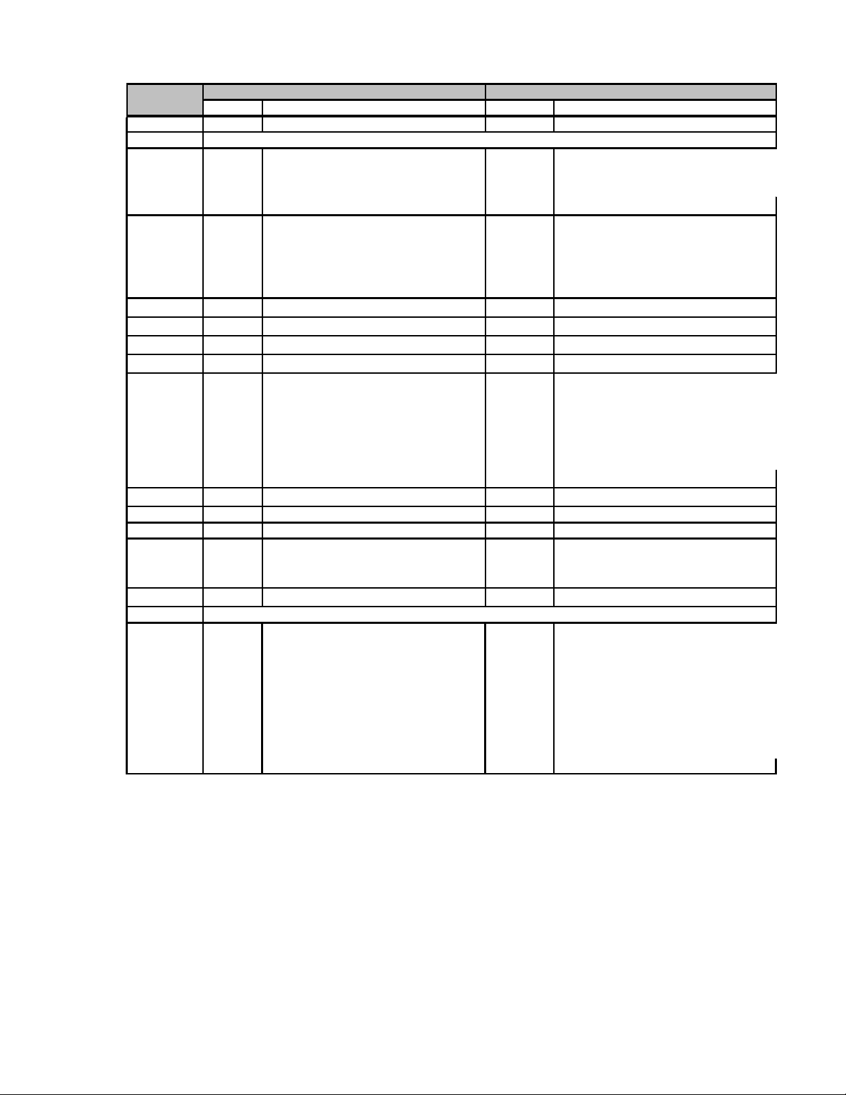
TABLE IV
Factory Identification
XXXX
●● ●
Page 29
34-ST-03-64
_ _
_ _
_ _
_ _
_ _
_ _
_ _
_ _
_ _
_ _
_
Page 29
RESTRICTIONS
Restriction
Letter
a
b
c
d
e
f
h
i
j
m
n
o
q
r
s
t
Table Table Selection
III
II
III
I, II
III
III
II
Available Only With
Selection
3D or 3H
Select only one option from this group
_ _ _ _ _ _ BF _ _ _ _,
_ _ _ _ _ _ BG _ _ _ _,
_ _ _ _ _ _ BH _ _ _ _,
_ _ _ _ _ _ JF _ _ _ _,
_ _ _ _ _ _ JG _ _ _ _,
SM
_ 2 _ - 2 _ _ _ _ _ _ _ _ _ _ _
1C or 2J
CR
0 _ _ _ _ _ _ _ _ _ _ _,
2 _ _ _ _ _ _ _ _ _ _ _
4 _ _ _ _ _ _ _ _ _ _ _
Must be specified with Model STR12D
II
III
II
III
III
III
I & II
Not Available With
_ _ _ _ _ _ BF _ _ _ _,
_ _ _ _ _ _ BG _ _ _ _,
_ _ _ _ _ _ JF _ _ _ _,
_ _ _ _ _ _ JG _ _ _ _,
4G
_ _ _ _ _ _ AF _ _ _ _
_ _ _ _ _ _ BF _ _ _ _
_ _ _ _ _ _ BG _ _ _ _
_ _ _ _ _ _ BH _ _ _ _
_ _ _ _ _ _ GG _ _ _ _
_ _ _ _ _ _ JF _ _ _ _
_ _ _ _ _ _ JG _ _ _ _
ME, FF
1C, 2J
TC, ME, 4G, 3S
2
- _ B _ _ _ _ _ _ _ _ _ _,
2
- _ C _ _ _ _ _ _ _ _ _ _,
2
- _ D _ _ _ _ _ _ _ _ _ _,
2
- _ E _ _ _ _ _ _ _ _ _ _,
2
- _ F _ _ _ _ _ _ _ _ _ _,
2
- _ H _ _ _ _ _ _ _ _ _ _,
2
- _ J _ _ _ _ _ _ _ _ _ _,
2
- _ K _ _ _ _ _ _ _ _ _ _,
2
- _ L _ _ _ _ _ _ _ _ _ _,
2
- _ M _ _ _ _ _ _ _ _ _
cont’d
Page 30

34-ST-03-64
_ _
_
_
_
_
_
Page 30
RESTRICTIONS (continued)
Restriction
Letter
u 1C, 2J
v
w
x FF, SM
y
z
1 F7
2 FB
3
4 II
5
6
7
8
9
10
11
14
15
16
21 III
22
Table Table Selection
III
I
III
I
I
II
II
III HC or H6 and WP
I
III SL
Available Only With
Selection
2 _ _
_ 2 _ _ _ _ _ _ _ _ _ _II
_ _ D
5 _
See Figure 23 in Specification
_ A _ _ _ _ _ _ _ _ _ _,
_ G _ _ _ _ _ _ _ _ _ _,
_ B _ _ _ _ _ _ _ _ _ _,
_ H _ _ _ _ _ _ _ _ _ _,
_ 2 _ _ _ _ _ _ _ _ _ _,
_ _ _ _ _ AA2_ _
_ _ _ _ _ AB2_ _
_ _ _ _ _ _ _ _ _ _ 0 _
_ _ C
FF
Not Available With
II
I
III
III
III
II
II
I
III
III
II
III
II
III
III
CC, G1, G2, N1, N2, OX, TP, MT, TC,
_ _ _ _ _ _ JA _ _ _ _
2
MB, SB, FB
_ _ _ _ _ _ _ _ _ _ _ 0
_ _ _ _ _ _ _ _ _ _ A _
1 _ _, 3 _ _
CR
FC, F1,
_ _ _ _ _ _ _ _ _ _ _ T
F7
_ _ _ _ _ _JJG_ _ _
_ _ _ _ _ _JKG_ _ _
_ _ _ _ _ _JLG_ _ _
_ _ _ _ _ _CAA_ _ _
_ _ _ _ _ _CCA_ _ _
_ _ _ _ _ _CCC_ _ _
FF, 00
FF
See ST-83 for Published Specials with pricing.
Note:
See ST-89 and User's Manual for part numbers.
See COMS Order Entry Information including TC, manuals, certificates, drawings and SPINS.
See ST-OD-1 for tagging, ID, Transmitter Configuration (TC) and calibration including factory default values.
To request a quote for a non-published "special", fax RFQ w/ Application Data Sht (34-ST-18-01) to Mktg. Applications.
See Specification 34-ST-03-64 for Seal dimensions.
Page 31
34-ST-03-64
Page 31
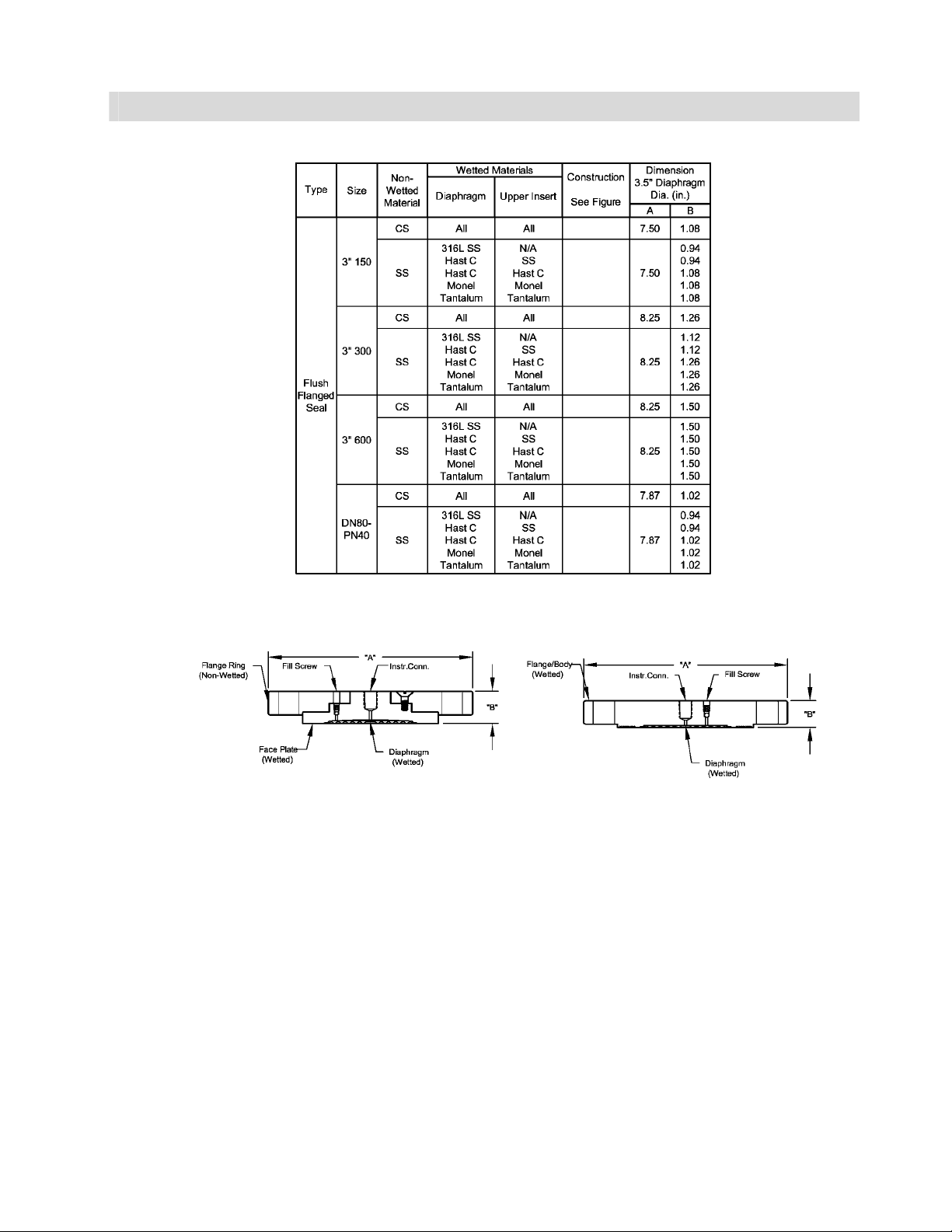
Dimensions and Drawings
20a
21a
20b
21b
20b
21b
20a
21a
20a
21a
20a
21a
20a
21a
20b
21b
20b
21b
20a
21a
20a
21a
20a
21a
20a
21a
20b
21b
20b
21b
20a
21a
20a
21a
20a
21a
20a
21a
20b
21b
20b
21b
20a
21a
20a
21a
20a
21a
Figure 20a. Flush Flanged Seal Figure 20b. Flush Flanged Seal
Figure 21a. Flush Flanged Seal Figure 21b. Flush Flanged Seal
Page 32

34-ST-03-64
Page 32
Dimensions and Drawings, cont.
Figure 21
Figure 22
Figure 22
Figure 23
Page 33

34-ST-03-64
Page 33
Dimensions and Drawings, cont.
Figure 23
Figure 24
Figure 24
Figure 25
Figure 25
Figure 26
Page 34

34-ST-03-64
Page 34
Dimensions and Drawings, cont.
Figure 26
Figure 27
Figure 27
Figure 28
Page 35

34-ST-03-64
Page 35
Dimensions and Drawings, cont.
Figure 28
Figure 29
Figure 29
Figure 30
Figure 30
Figure 31
Figure 20Figure 20
Figure 20Figure 20
Page 36

34-ST-03-64
Page 36
THIS PAGE INTENTIONALLY BLANK
ST 3000® is a registered trademark of Honeywell International Inc.
HART* is a trademark of the Hart Communication Foundation.
FOUNDATION™ is a trademark of the Fieldbus Foundation.
Honeywell Field Solutions
Honeywell International Inc.
2500 W. Union Hill Drive
Phoenix, Arizona 85027 ©Honeywell International Inc.
 Loading...