

Page 1

ST 700
SmartLine Pressure Transmitters
User’s Manual
34-ST-25-44
Revision 2.0
May 2013
Honeywell Process Solutions
Page 2

Page ii ST 700 SmartLine Pressure Transmitters User’s Manual Revision 2.0
Page 3

Copyrights, Notices and Trademarks
© Copyright 2013 by Honeywell, Inc.
Revision 2, May 2013
While the information in this document is presented in good faith and believed to be
accurate, Honeywell disclaims any implied warranties of merchantability and fitness for a
particular purpose and makes no express warranties except as may be stated in the written
agreement with and for its customers. In no event is Honeywell liable to anyone for any
indirect, special, or consequential damages. The information and specifications in this
document are subject to change without notice.
Honeywell, TDC 3000, SFC, Smartline, PlantScape, Experion PKS, and TotalPlant are
registered trademarks of Honeywell International Inc. Other brand or product names are
trademarks of their respective owners.
Honeywell Process Solutions
1860 Rose Garden Lane
Phoenix, AZ 85027
Revision 2.0 ST 700 Smart Pressure Transmitter User’s Manual Page iii
Page 4

About This Manual
This manual is a detailed how to reference for installing, piping, wiring, configuring, starting up,
operating, maintaining, calibrating, and servicing Honeywell’s family of ST 700 SmartLine
Pressure Transmitters. Users who have a Honeywell ST 700 SmartLine Pressure Transmitter
configured for HART protocol or Honeywell’s Digitally Enhanced (DE) are referred to the ST
700 Series HART/DE Option User’s Manual, document number 34-ST-25-47. Users who have a
Honeywell ST 700 SmartLine Pressure Transmitter configured for Fieldbus operation are referred
to the ST 700 Series Fieldbus Option User’s Manual, document number (34-ST-25-48).
The configuration of your Transmitter depends on the mode of operation and the options selected
for it with respect to operating controls, displays and mechanical installation. This manual
provides detailed procedures to assist first-time users, and it further includes keystroke
summaries, where appropriate, as quick reference or refreshers for experienced personnel.
To digitally integrate a Transmitter with one of the following systems:
• For the Experion PKS, you will need to supplement the information in this document with the
data and procedures in the Experion Knowledge Builder.
• For Honeywell’s TotalPlant Solutions (TPS), you will need to supplement the information in
this document with the data in the PM/APM SmartLine Transmitter Integration Manual,
which is supplied with the TDC 3000 book set. (TPS is the evolution of the TDC 3000).
Release Information
ST 700 SmartLine Pressure Transmitter User Manual, Document # 34-ST-25-44,
Revision 1.0, February, 2013
Revision 2.0, May, 2013 – Updates to Parts list, Explosionproof Seal class, Fail Safe and Comms
Module procedures.
References
The following list identifies publications that may contain information relevant to the information
in this document.
SmartLine Pressure Transmitter Quick Start Installation Guide, Document # 34-ST-25-36
ST 800 & ST 700 Pressure Transmitter with HART Safety Manual, # 34-ST-25-37
ST 700 SmartLine Pressure Transmitter HART/DE Option User’s Manual, Document
# 34-ST-25-47
ST 700 FF Transmitter with FOUNDATION Fieldbus Option Installation & Device Reference
Guide, Document # 34-ST-25-48
MC Tookit User Manual, for 400 or later, Document # 34-ST-25-20
PM/APM Smartline Transmitter Integration Manual, Document # PM 12-410
ST 800 & ST 700 Series Pressure, Analog, HART and DE Communications form, Honeywell
drawing 50049892
Smart Field Communicator Model STS 103 Operating Guide, Document # 34-ST-11-14
Page iv ST 700 SmartLine Pressure Transmitters User’s Manual Revision 2.0
Page 5

Patent Notice
The Honeywell ST 700 SmartLine Pressure Transmitter family is covered by one or more of the
following U. S. Patents: 5,485,753; 5,811,690; 6,041,659; 6,055,633; 7,786,878; 8,073,098; and other
patents pending.
Support and Contact Information
For Europe, Asia Pacific, North and South America contact details, refer to the back page of this
manual or the appropriate Honeywell Solution Support web site:
Honeywell Corporate www.honeywellprocess.com
Honeywell Process Solutions www.honeywellprocess.com/pressue-transmitters/
Training Classes http://www.automationccollege.com
Telephone and Email Contacts
Area Organization Phone Number
United States and
Canada
Global Email
Support
Honeywell Inc.
Honeywell Process
Solutions
1-800-343-0228 Customer Service
1-800-423-9883 Global Technical Support
Revision 2.0 ST 700 Smart Pressure Transmitter User’s Manual Page v
Page 6
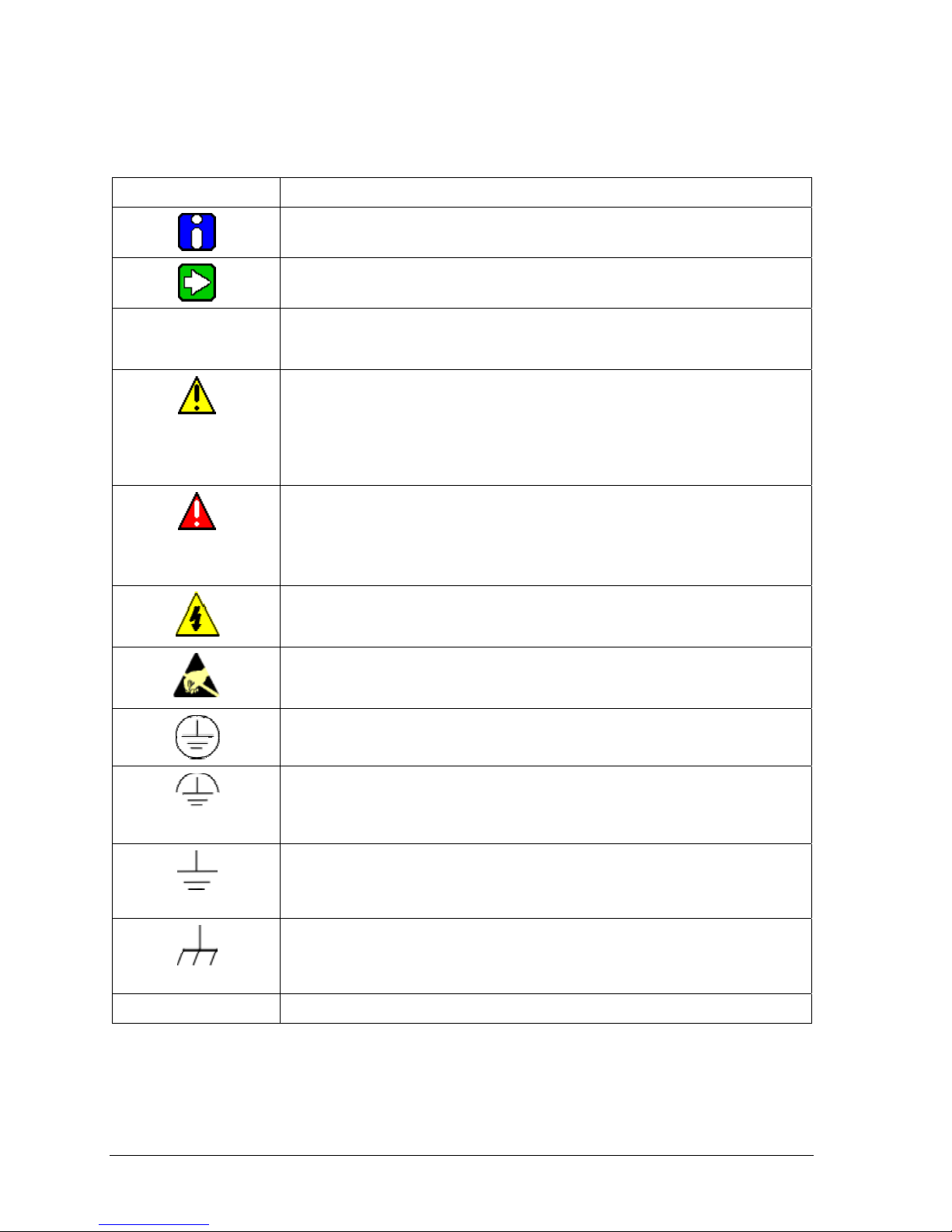
Symbol Descriptions and Definitions
The symbols identified and defined in the following table may appear in this document.
Symbol Definition
CAUTION
ATTENTION: Identifies information that requires special consideration.
TIP: Identifies advice or hints for the user, often in terms of performing a
Indicates a situation which, if not avoided, may result in equipment or work
(data) on the system being damaged or lost, or may result in the inability to
CAUTION: Indicates a potentially hazardous situation which, if not avoided,
may result in minor or moderate injury. It may also be used to alert against
CAUTION symbol on the equipment refers the user to the product manual for
additional information. The symbol appears next to required information in
WARNING: Indicates a potentially hazardous situation, which, if not avoided,
WARNING symbol on the equipment refers the user to the product manual
for additional information. The symbol appears next to required information
WARNING, Risk of electrical shock: Potential shock hazard where
HAZARDOUS LIVE voltages greater than 30 Vrms, 42.4 Vpeak, or 60 VDC
ESD HAZARD: Danger of an electro-static discharge to which equ i pment may
be sensitive. Observe precautions for handling electrostatic sensitive
Protective Earth (PE) terminal: Provided for connection of the protective
earth (green or green/yellow) supply system conductor.
Functional earth terminal: Used for non-safety purposes such as noise
immunity improvement. NOTE: This connection shall be bonded to
Protective Earth at the source of supply in accordance with national local
Earth Ground: Functional earth connection. NOTE: This connection shall be
bonded to Protective Earth at the source of supply in accordance with
national and local electrical code requirements.
properly operate the process.
could result in serious injury or death.
may be accessible.
electrical code requirements.
task.
unsafe practices.
the manual.
in the manual.
devices.
Chassis Ground: Identifies a connection to the chassis or frame of the
continued
equipment shall be bonded to Protective Earth at the source of supply in
Page vi ST 700 SmartLine Pressure Transmitters User’s Manual Revision 2.0
accordance with national and local electrical code requirements.
Page 7
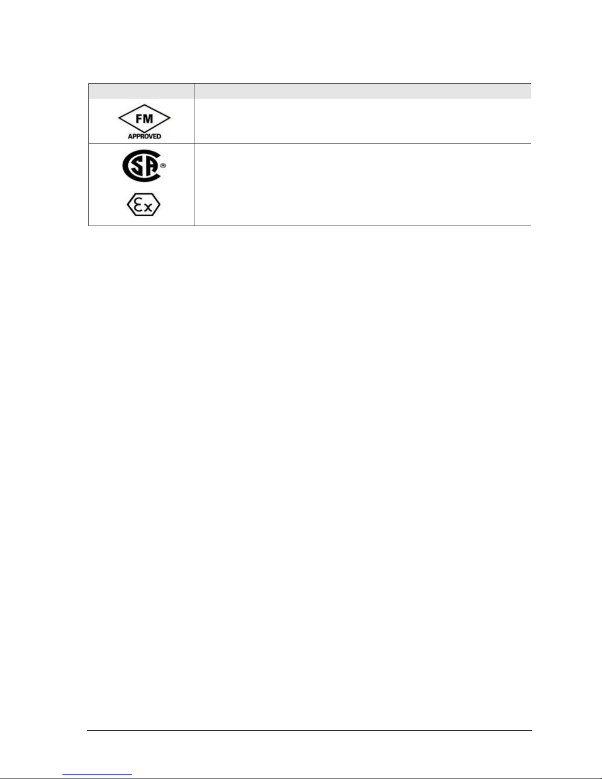
Symbol Description
®
The Factory Mutual
tested and certified to be reliable.
The Canadian Standards mark means the equipment has been tested and meets
applicable standards for safety and/or performance.
The Ex mark means the equipment complies with the requirements of the
European standards that are harmonised with the 94/9/EC Directive (ATEX
Directive, named after the French "ATmosphere EXplosible").
Approval mark means the equipment has been rigorously
Revision 2.0 ST 700 Smart Pressure Transmitter User’s Manual Page vii
Page 8

Contents
1 Introduction .................................................................................................................................... 1
1.1 Overview ................................................................................................................................ 1
1.2 Features and Options .............................................................................................................. 1
1.2.1 Physical Characteristics ................................................................................................. 1
1.2.2 Functional Characteristics .............................................................................................. 2
1.3 ST 700 Transmitter Nameplate .............................................................................................. 3
1.4 Safety Certification Information ............................................................................................ 3
1.5 Transmitter Adjustments ........................................................................................................ 3
1.6 Display Options ..................................................................................................................... 4
1.7 Optional 3-Button Assembly ................................................................................................. 4
2 Application Design ........................................................................................................................ 5
2.1 Overview ................................................................................................................................ 5
2.1.1 Accuracy ........................................................................................................................ 5
2.1.2 Diagnostic Messages ...................................................................................................... 5
2.2 Safety ..................................................................................................................................... 6
2.2.1 Safety Integrity Level (SIL) ........................................................................................... 6
3 Installation and Startup .................................................................................................................. 7
3.1 Installation Site Evaluation .................................................................................................... 7
3.2 Honeywell MC Toolkit .......................................................................................................... 7
3.3 Display Installation Precautions ............................................................................................. 7
3.4 Mounting ST 700 SmartLine Pressure Transmitters .............................................................. 8
3.4.1 Summary ........................................................................................................................ 8
3.4.2 Mounting Di
3.4.3 Bracket Mounting Procedure ......................................................................................... 9
3.4.4 Mounting Transmitters with Small Absolute or Differential Pressure Spans .............. 11
3.4.5 Flange Mounting .......................................................................................................... 12
3.4.6 Remote Diaphragm Seal Mounting Information .......................................................... 13
3.5 Piping the ST 700 Transmitter ............................................................................................. 14
3.5.1 Piping Arrangements .................................................................................................... 14
3.5.2 Suggestions for Transmitter Location .......................................................................... 15
3.5.3 General Piping Guidelines ........................................................................................... 15
3.5.4 Procedure to Install Flange Adapters ........................................................................... 15
3.6 Wiring a Transmitter ............................................................................................................ 16
3.6.1 Overview ...................................................................................................................... 16
3.6.2 Digital System Integration Information ....................................................................... 18
3.6.3 Wiring Variations ......................................................................................................... 18
3.6.4 Wiring Procedure ......................................................................................................... 18
3.6.5 Lightning Protection .................................................................................................... 18
3.6.6 Supply Voltage Limiting Requirements ....................................................................... 18
3.6.7 Process Sealing ............................................................................................................ 19
3.6.8 Explosion-Proof Conduit Seal ..................................................................................... 19
3.7 Startup .................................................................................................................................. 19
3.7.1 Overview ...................................................................................................................... 19
3.7.2 Startup Tasks ................................................................................................................ 19
3.7.3 Output Check Procedures ............................................................................................. 20
3.7.4 Constant Current Source Mode Procedure
mensions
.................................................................................................... 8
...................................................................
20
Page viii ST 700 SmartLine Pressure Transmitters User’s Manual Revision 2.0
Page 9

4 Operation ...................................................................................................................................... 22
4.1 Overview .............................................................................................................................. 22
4.2 Three-Button Operation ........................................................................................................ 22
4.2.1 The Basic Display Menu .............................................................................................. 23
4.2.2 Data Entry ..................................................................................................................... 27
4.2.3 Editing a Numeric value ............................................................................................... 27
4.2.4 Selecting a new setting from a list of choices .............................................................. 27
4.3 Three Button Operation with no Display Installed ............................................................... 28
4.3.1 Zero Adjustment ........................................................................................................... 28
4.3.2 Span Adjustment .......................................................................................................... 28
4.4 Changing the Default Failsafe Direction .............................................................................. 28
4.4.1 DE and Analog Differences .......................................................................................... 28
4.4.2 Procedure to Establish Failsafe Operation .................................................................... 29
4.5 Monitoring the Basic Display ............................................................................................... 32
4.5.1 Basic Display ................................................................................................................ 32
5 Maintenance ................................................................................................................................. 33
5.1 Overview .............................................................................................................................. 33
5.2 Preventive Maintenance Practices and Schedules ................................................................ 33
5.3 Inspecting and Cleaning Barrier Diaphragms ...................................................................... 33
5.4 Replacing the Communication Module ................................................................................ 36
5.5 Replacing the Meter Body .................................................................................................... 38
6 Calibration .................................................................................................................................... 42
6.1 Recommendations for Transmitter Calibration .................................................................... 42
6.2 Calibration Procedures
7 Troubleshoot
7.1 Overview .............................................................................................................................. 43
7.2 Critical Diagnostics Screens ................................................................................................. 43
7.2.1 Fault Conditions and Recommended Corrective Actions ............................................ 43
8 Parts List ....................................................................................................................................... 44
8 Parts List ....................................................................................................................................... 44
8.1 Overview .............................................................................................................................. 44
Appendix A. PRODUCT CERTIFICATIONS .................................................................................... 56
Index ..................................................................................................................................................... 68
ing ............................................................................................................................ 43
......................................................................................................... 42
Revision 2.0 ST 700 Smart Pressure Transmitter User’s Manual Page ix
Page 10

List of Figures
Figure 1 – ST 700 Major Assemblies .................................................................................................... 2
Figure 2 – Electronics Housing Components ........................................................................................ 2
Figure 3 –Typical ST 700 Name Plate ................................................................................................... 3
Figure 4 – Typical Bracket Mounted and Flange Mounted Installations ............................................... 8
Figure 5 – Angle Mounting Bracket Secured to a Horizontal or Vertical Pipe ..................................... 9
Figure 6 – Inline Model Mounted to an Optional Bracket ................................................................... 10
Figure 7 – Rotating the Electronics Housing ....................................................................................... 10
Figure 8 – Using a Spirit Balance to Level a Transmitter .................................................................... 11
Figure 9 – Tank-Flange Mounted Transmitter ..................................................................................... 12
Figure 10 – Representative Remote Diaphragm Seal Transmitter Installation .................................... 13
Figure 11 – Typical 3-Valve Manifold with Blow-Down Piping ........................................................ 14
Figure 12 – Flange Adapter Removal and Replacement ..................................................................... 16
Figure 13 – Transmitter Operating Ranges .......................................................................................... 16
Figure 14 – Transmitter 3-Screw Terminal Board and Grounding Screw ........................................... 17
Figure 15 – Current Loop Test Connections ........................................................................................ 20
Figure 16 – Three-Button Option ......................................................................................................... 22
Figure 17 – Locating the Failsafe and Write Protect Jumpers ............................................................. 29
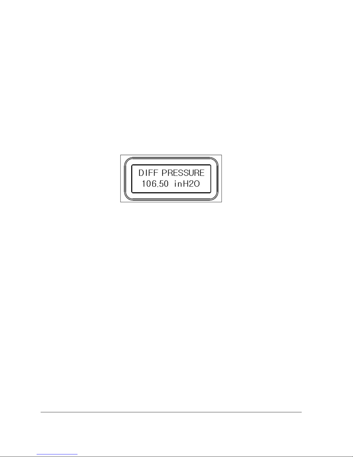
Figure 18 – Basic Display with Process Variable Format ................................................................... 32
Figure 19 – DP Transmitter Head Disassembly ................................................................................... 34
Figure 20 – Head Bolt Tightening Sequence ....................................................................................... 35
Figure 21 – PWA Replacement ........................................................................................................... 36
Figure 22 – Disassembly for Meter Body Replacement ...................................................................... 38
Figure 23 – Hardware Location to Remove the Meter Assembly ....................................................... 39
Figure 24 – Meter Body Reassembly ................................................................................................... 40
Figure 25 – Head Bolt Tightening Sequence ....................................................................................... 40
Figure 26 – Angle and Flat Bracket Parts ............................................................................................ 45
Figure 27 – Electronic Housing, Display End ..................................................................................... 47
Figure 28 – Electronic Housing, Terminal Block End ......................................................................... 48
Figure 29 – Transmitter Major Assemblies ......................................................................................... 49
Figure 30 - ST 700 Models STD710, 720, 730, & 770 ........................................................................ 51
Figure 31 – STG730, 740, 770, and STA722, 740 Transmitter Body (Ref.) ....................................... 53
Figure 32 – Inline Gauge and Inline Atmospheric Meter Body Bodies ............................................... 53
Page x ST 700 SmartLine Pressure Transmitters User’ s Manual Revision 2.0
Page 11

List of Tables
Table 1 – Features and Options .............................................................................................................. 1
Table 2 – Available Display Characteristics .......................................................................................... 4
Table 3 – ST 700 Standard Diagnostics Messages ................................................................................. 5
Table 4 - Mounting Bracket procedure ..................................................................................................... 9
Table 5 – Flange Mounting Guidelines ................................................................................................ 13
Table 6 – Remote Diaphragm Mounting Details .................................................................................. 13
Table 7 – Suggested Connection Locations ......................................................................................... 15
Table 8 – Three-Button Option Functions ............................................................................................ 23
Table 9 – The Basic Display Menus ..................................................................................................... 23
Table 10 – Three-Button Data Entry .................................................................................................... 27
Table 11 – Hart and DE Failsafe and Write Protect Jumpers ............................................................... 30
Table 12 – Fieldbus Simulation and Write Protect Jumpers ................................................................ 30
Table 13 – Head Bolt Torque Values ................................................................................................... 35
Table 14 – Fault Conditions and Recommended Corrective Actions. ................................................. 43
Table 15 – Summary List of Recommended Spare Parts ..................................................................... 44
Table 16 – Angle and Flat Bracket Parts .............................................................................................. 4
Table 17 – Tr
Table 18 – S
Table 19 - I Parts for STG730, 740, 770 and STA722, 740 Transmitter Body .................................... 5
Table 20 - Inline Gauge and Inline Atmospheric Meter Body Parts .................................................... 53
Table 21 – Flange-Mounted Meter Body Parts (Ref Figure 32) .......................................................... 54
ansmitter Major Assemblies ........................................................................................... 4
T 700 Models STD710, 720, 730, 770 & STG774 (Ref. Figure 29) .............................. 50
6
7
2
Revision 2.0 ST 700 Smart Pressure Transmitter User’s Manual Page xi
Page 12

Page xii ST 700 SmartLine Pressure Transmitters User’s Manual Revision 2.0
Page 13

1 Introduction
1.1 Overview
This section is an introduction to the physical and functional characteristics Honeywell’s family of
ST 700 SmartLine Pressure Transmitters.
1.2 Features and Options
The ST 700 SmartLine Pressure Transmitter is available in a variety of models for measuring
Differential Pressure (DP), Gauge Pressure (GP), and Absolute Pressure (AP). Table 1 lists the
protocols, human interface (HMI), materials, approvals, and mounting bracket options for the ST 700.
Table 1 – Features and Options
Feature/Option Standard/Available Options
Communication Protocols HART version 7, Digitally Enhanced (DE), Fieldbus
Human-Machine Interface (HMI)
Options (Basic Display)
Calibration Single
Approvals (See Appendix C for details.) ATEX, CSA, FM, IECx, NEPSI
Mounting Brackets Angle/flat carbon steel/304 and 316 stainless steel, Marine
Integration Tools Experion
Basic Digital Display
Three-button programming (optional)
Basic display language: English only
304 stainless steel
1.2.1 Physical Characteristics
As shown in Figure 1, the ST 700 is packaged in two major assemblies: the Electronics Housing and
the Meter Body. The elements in the Electronic Housing respond to setup commands and execute the
software and protocol for the different pressure measurement types. Figure 2 shows the assemblies in
the Electronics Housing with available options.
The Meter Body provides connection to a process system. Several physical interface configurations
are available, as determined by the mounting and mechanical connections, all of which are described
in the “Installation” section of this manual.
Page iii ST 800 SmartLine Pressure Transmitters User’s Manual Revision 1.0
Page 14
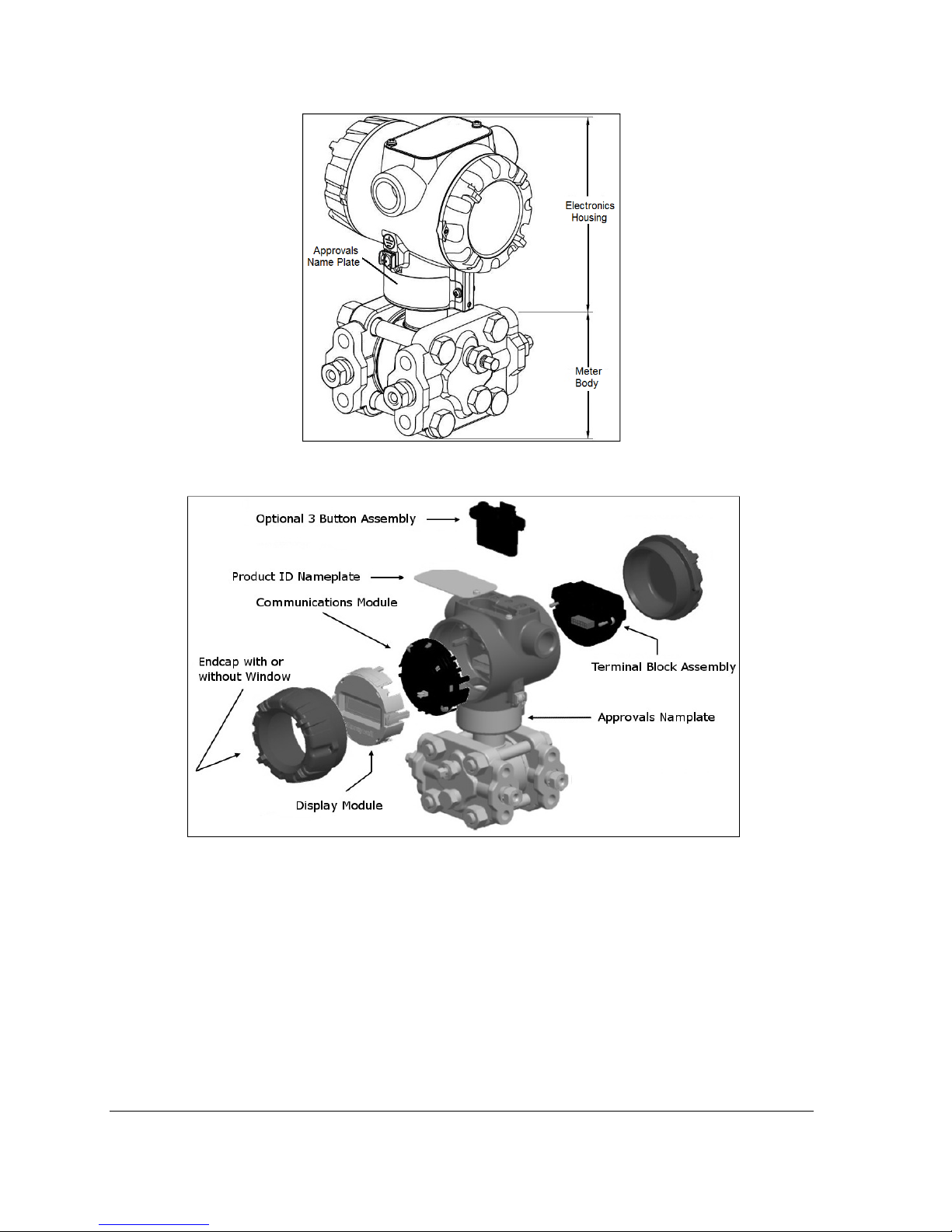
Figure 1 – ST 700 Major Assemblies
Figure 2 – Electronics Housing Components
1.2.2 Functional Characteristics
Functionally, the Transmitter can measure process pressure and provides a proportional analog 4 to
20 mA output to the measured process variable (PV). Available output communication protocols
include Honeywell Digitally Enhanced (DE), HART, and FOUNDATION Fieldbus.
An optional 3-button assembly is available to set up and make adjustments to the Transmitter. In
addition, a Honeywell Multi-Communication (MC) Toolkit (not supplied with the Transmitter) can
facilitate setup and adjustment procedures. Certain adjustments can be made through an Experion
Station or a Universal Station if the Transmitter is digitally integrated with Honeywell’s Experion or
TPS/TDC 3000 control system.
Page 72 ST 700 SmartLine Pressure Transmitters User’s Manual Revision 1.0
Page 15
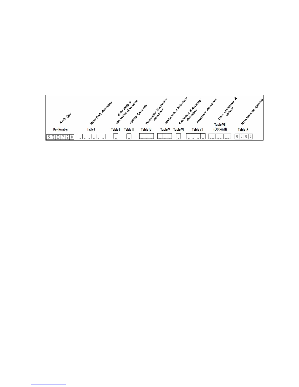
1.3 ST 700 Transmitter Nameplate
The Transmitter nameplate mounted on the bottom of the electronics housing (see Figure 1) lists its
model number, physical configuration, electronics options, accessories, certifications, and
manufacturing specialties. Figure 3 is an example of a typical Gauge Pressure (GP) or Atmospheric
Pressure (AP) Transmitter name plate. The model number format consists of a Key Number with
several table selections. The Differential Pressure (DP), Absolute Pressure (AP), and Gauge Pressure
(GP) name plates are essentially the same. However, the DP provides one additional entry (7 vs. 6) in
the Meter Body Selections (Table I) to accommodate the static pressure rating.
Figure 3 –Typical ST 700 Name Plate
You can readily identify the series and basic Transmitter type from the third and fourth digits in the
key number. The letter in the third digit represents one of these basic transmitter types:
• A = Absolute Pressure • D = Differential Pressure • F = Flange Mounted
• G = Gauge Pressure • R = Remote Seals
For a complete selection breakdown, refer to the appropriate Specification and Model Selection
Guide provided as a separate document.
1.4 Safety Certification Information
An “approvals” name plate is located on the bottom of the Electronics Assembly; see Figure 1for
exact location. The approvals name plate contains information and service marks that disclose the
Transmitter compliance information. Refer to Appendix C of this document for safety certification
requirements and details.
1.5 Transmitter Adjustments
Zero and Span adjustments are possible in ST 700 SmartLine Pressure Transmitters with the optional
three-button assembly located at the top of the Electronic Housing (see Figure 2).
You can also use the Honeywell MC Toolkit or other third-party hand-held zero to make any
adjustments to an ST 700 SmartLine Pressure Transmitter. Alternately, certain adjustments can be
made through the Experion or Universal Station, if the Transmitter is digitally integrated with a
Honeywell Experion or TPS system.
Revision 2.0 ST 700 Smart Pressure Transmitter User’s Manual Page 3
Page 16

1.6 Display Options
The ST 700 SmartLine Pressure Transmitter with Basic Display.
Table 2 – Available Display Characteristics
Basic Display
• Suitable for basic process needs
• 360
• 2 lines, 16 characters
• Standard units-of-measurement: Pa, KPa, MPa, KGcm2, TORR, ATM, inH2O,
• Diagnostic messaging
• Square root output indications
o
rotation in 90o Increments
mH2O, bar, mbar, inHg, FTH2O, mmH2O, MMHG, & PSI
1.7 Optional 3-Button Assembly
The optional 3-Button Assembly provides the following features and capabilities:
• Increment, decrement, and enter key functions.
• With the menu-driven display:
o Comprehensive on-screen menu for navigation.
o Transmitter configuration.
o Transmitter calibration
o Display configuration.
o Set zero and span parameters.
Page 72 ST 700 SmartLine Pressure Transmitters User’s Manual Revision 1.0
Page 17

2 Application Design
2.1 Overview
This section discusses the considerations involved with deploying a Honeywell ST 700 SmartLine
Pressure Transmitter in a process system. The following areas are covered:
• Safety
• Input and output data
• Reliability
• Environmental limits
• Installation considerations
• Operation and maintenance\
• Repair and replacement
2.1.1 Accuracy
The ST 700 SmartLine Pressure Transmitter (Transmitter) measures the gauge, differential, or
absolute pressure of a process and reports the measurement to a receiving device. Measurements are
accurate up to 0.05 of the calibrated span.
2.1.2 Diagnostic Messages
Transmitter standard diagnostics are reported in the two basic categories listed in Table 3. Problems
detected as critical diagnostics drive the analog output to the programmed burnout level. Problems
detected as non-critical diagnostics may affect performance without driving the analog output to the
programmed burnout level. Informational messages (not listed in Table 3) report various Transmitter
status or setting conditions. The messages listed in Table 3 are specific to the Transmitter, exclusive
of those associated with HART and DE protocols. HART and DE diagnostic messages are listed and
described in the ST 700 SmartLine Pressure Transmitter HART/DE Option User Manual, document
number 34-ST-25-47.
Table 3 – ST 700 Standard Diagnostics Messages
Critical Diagnostics
(Failure Conditions)
Sensor Comm Timeout
Meter Body Critical Failure
Electronic Module Diag Failure
Config Data Corrupt
Meter Body NVM Corrupt
Electronic Module DAC Failure
No DAC Compensation
No Factory Calibration
PV Out of Range
Fixed Current Mode
Sensor Over Temperature
Meter Body Excess Correct
No DAC Compensation
No Factory Calibration
Local Display
Low Supply Voltage
Non-Critical Diagnostics (Warning Conditions)
No DAC Calibration
Tamper Alarm
Meter Body Unreliable Comm
Loop Current Noise
AO Out of Range
URV Set Error – Span Config
Button
LRV Set Error – Span Config
Button
Revision 2.0 ST 700 Smart Pressure Transmitter User’s Manual Page 5
Page 18

2.2 Safety
2.2.1 Safety Integrity Level (SIL)
The ST 700 is intended to achieve sufficient integrity against systematic errors by the manufacturer’s
design. A Safety Instrumented Function (SIF) designed with this product must not be used at a SIL
level higher than the statement, without “prior use” justification by the end user or diverse technology
redundancy in the design. Refer to the Honeywell SmartLine Safety Manual, 34-ST-25-37, for
additional information.
Page 72 ST 700 SmartLine Pressure Transmitters User’s Manual Revision 1.0
Page 19

3 Installation and Startup
3.1 Installation Site Evaluation
Evaluate the site selected for the ST 700 Transmitter installation with respect to the process system
design specifications and Honeywell’s published performance characteristics for your particular
model. Some parameters that you may want to include in your site evaluation are:
• Environmental Conditions:
o Ambient Temperature
o Relative Humidity
• Potential Noise Sources:
o Radio Frequency Interference (RFI)
o Electromagnetic Interference (EMI)
• Vibration Sources
o Pumps
o Motorized System Devices (e.g., pumps)
o Valve Cavitation
• Process Parameters
o Temperature
o Maximum Pressure Rating
3.2 Honeywell MC Toolkit
In preparation for post-installation processes, refer to the MC Tookit User Manual, Document # 34-
ST-25-20, for battery conditioning and device operation and maintenance information.
3.3 Display Installation Precautions
Temperature extremes can affect display quality. The display can become unreadable at temperature
extremes; however, this is only a temporary condition. The display will again be readable when
temperatures return to within operable limits.
The display update rate may increase at cold temperature extremes, but as with readability, normal
updating resumes when temperatures are within limits for full operability.
Revision 2.0 ST 700 Smart Pressure Transmitter User’s Manual Page 7
Page 20
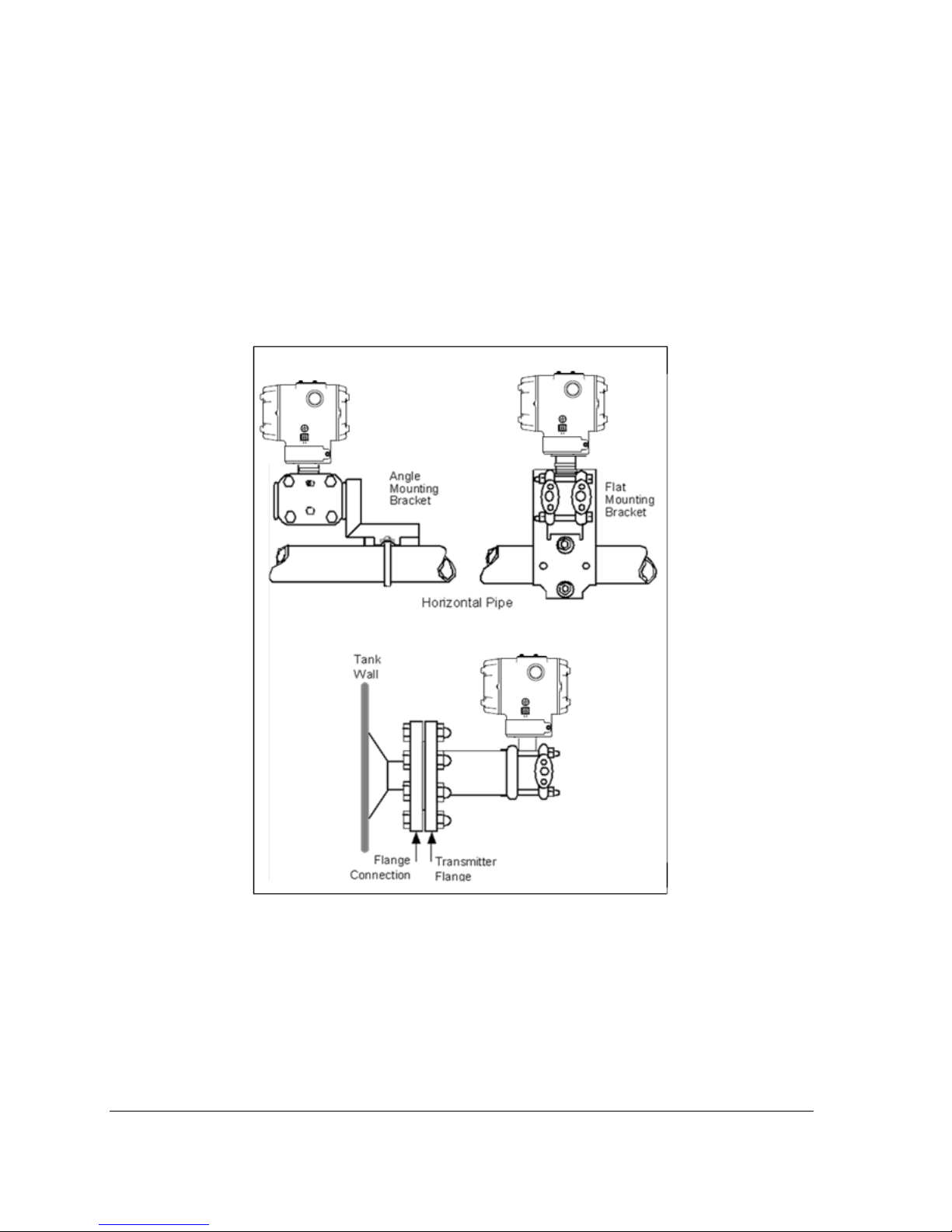
3.4 Mounting ST 700 SmartLine Pressure Transmitters
3.4.1 Summary
Transmitter models, except flush mounts and those with integral flanges, can be attached to a twoinch (50 millimeter) vertical or horizontal pipe using Honeywell’s optional angle or flat mounting
bracket; alternately you can use your own bracket. Flush-mount models are attached directly to a
process pipe or tank by a one-inch weld nipple. Models with integral flanges are supported by the
flange connection.
Figure 4 shows typical bracket-mounted and flange-mounted transmitter installations.
Figure 4 – Typical Bracket Mounted and Flange Mounted Installations
3.4.2 Mounting Dimensions
Refer to Honeywell drawing number 50049930 (Dual Head), 50049931 (In-Line), 50049932 (Flange
Mount) 50049933 (Extended Flange), and 50049934 (Remote Seal) for detailed dimensions.
Abbreviated overall dimensions are also shown on the Specification Sheets for the transmitter
models. This section assumes that the mounting dimensions have already been taken into account and
the mounting area can accommodate the Transmitter.
Page 72 ST 700 SmartLine Pressure Transmitters User’s Manual Revision 1.0
Page 21
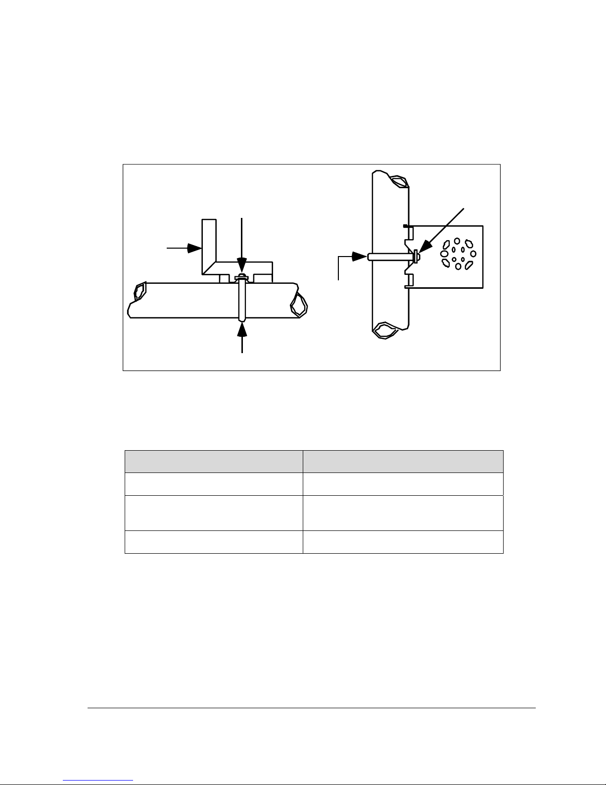
3.4.3 Bracket Mounting Procedure
If you are using an optional bracket, start with Step 1. For an existing bracket, start with Step 2.
1. Refer to Figure 5. Position the bracket on a 2-inch (50.8 mm) horizontal or vertical pipe, and
install a “U” bolt around the pipe and through the holes in the bracket. Secure the bracket
with the nuts and lock washers provided.
Nuts and
Lockwashers
Mounting
Bracket
U-Bolt
Nuts and
Lockwashers
Mounting
Bracket
Horizontal Pipe
Vertical P ipe
U-Bolt
Figure 5 – Angle Mounting Bracket Secured to a Horizontal or Vertical Pipe
2. Align the appropriate mounting holes in the Transmitter with the holes in the bracket. Use the
bolts and washers provided to secure the Transmitter to the bracket; see the following
variations.
Table 4 Mounting Bracket procedure
Transmitter Type Use Hardware
DP with double-ended process heads
and/or remote seals
In-line GP and AP (STGxxL and
STAxxL)
Dual-head GP and AP
EXAMPLE: Inline model mounted to an optional angle bracket. See Figure 6.
Alternate mounting holes in the ends of the
heads
The smaller “U” bolt provided to attach the
meter body to the bracket. See the
following example.
Mounting holes in the end of the process
head.
Revision 2.0 ST 700 Smart Pressure Transmitter User’s Manual Page 9
Page 22
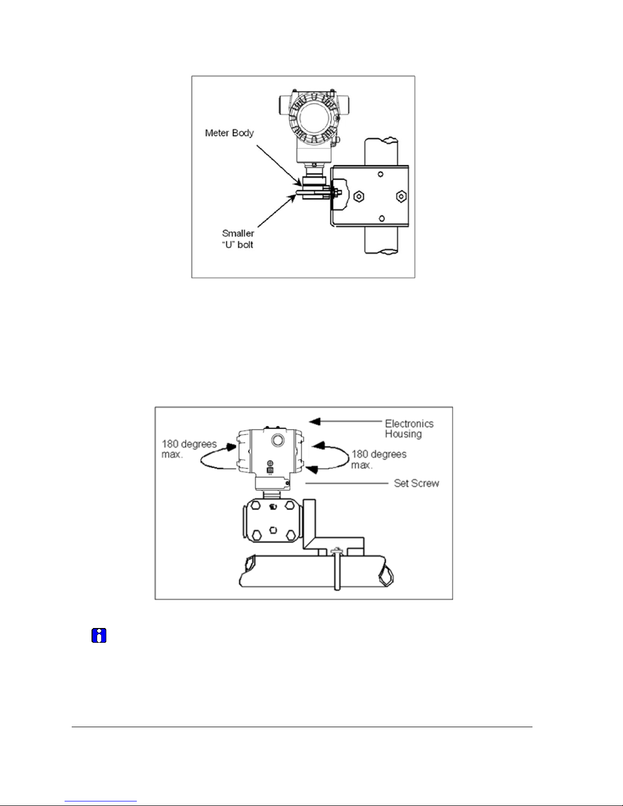
Figure 6 – Inline Model Mounted to an Optional Bracket
3. Loosen the set screw on the outside neck of the Transmitter one (1) full turn.
4. Rotate the Electronics housing a maximum of 180
o
left or right from the center to the position
you require, and tighten the set screw 8.9 to 9.7 pound-inches (1.40 to 1.68 Newton meters),
using a 4mm metric socket head wrench. See the following example and Figure 7.
EXAMPLE: Rotating the Electronics Housing
Figure 7 – Rotating the Electronics Housing
The mounting position of absolute pressure models STA822, STA82L, or a draft
range model STD810 is critical as the Transmitter spans become smaller.
A maximum zero shift of 2.5 mmHg for an Absolute Transmitter or 1.5 inches of
water (inH
that is rotated 90
O) for a Draft Range Transmitter can result from a mounting position
2
o
from the vertical. A typical zero-shift of 0.12 mmHg or 0.20 inH2O
can occur for a five (5)-degree rotation from the vertical.
Page 72 ST 700 SmartLine Pressure Transmitters User’s Manual Revision 1.0
Page 23
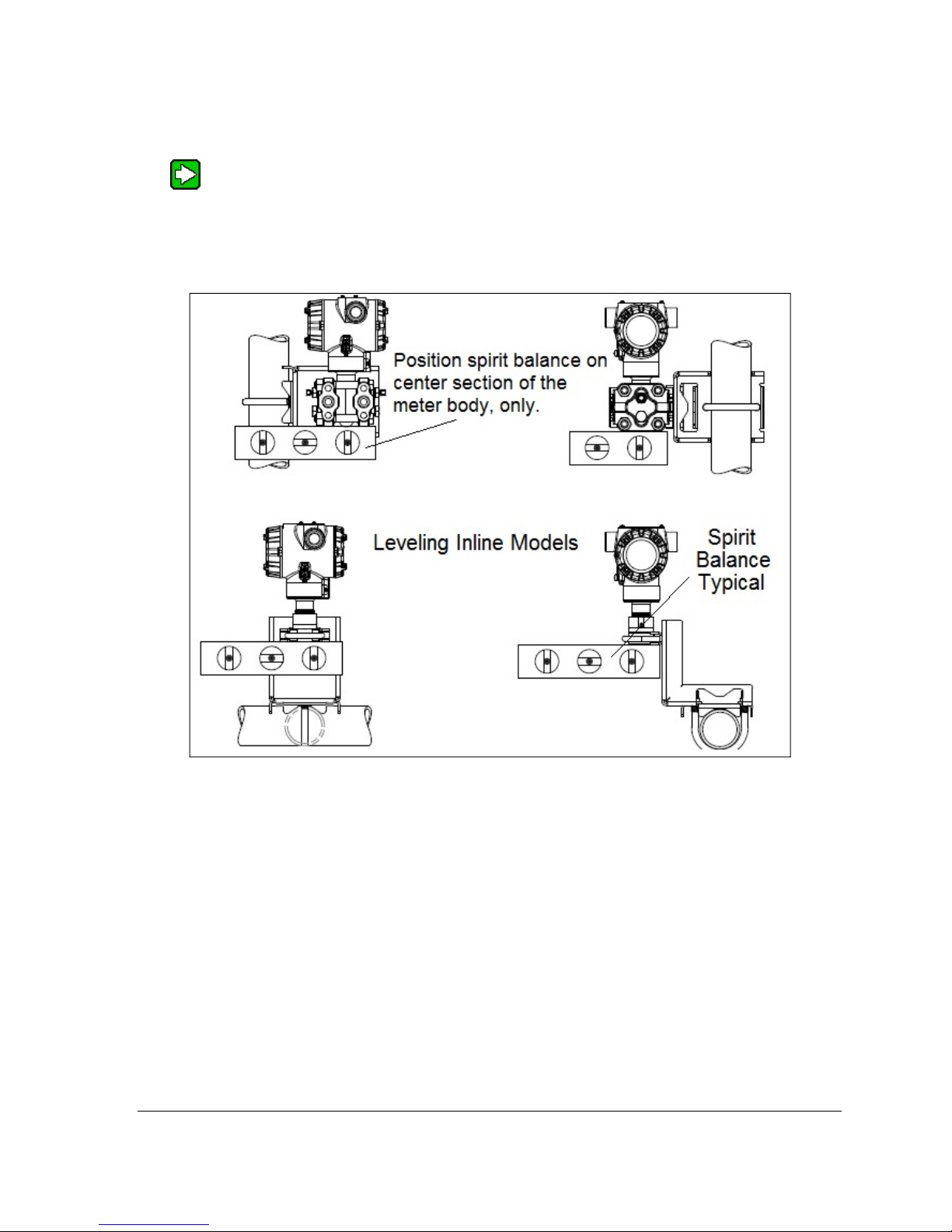
3.4.4 Mounting Transmitters with Small Absolute or Differential Pressure
Spans
To minimize positional effects on calibration (zero shift), take the appropriate
mounting precautions for the respective Transmitter model. For a model STA722 or
STA72L, ensure that the Transmitter is vertical when mounting it. You do this by
leveling the Transmitter side-to-side and front-to-back. Figure 8 shows how to level
a Transmitter using a spirit level.
Figure 8 – Using a Spirit Balance to Level a Transmitter
Revision 2.0 ST 700 Smart Pressure Transmitter User’s Manual Page 11
Page 24
3.4.5 Flange Mounting
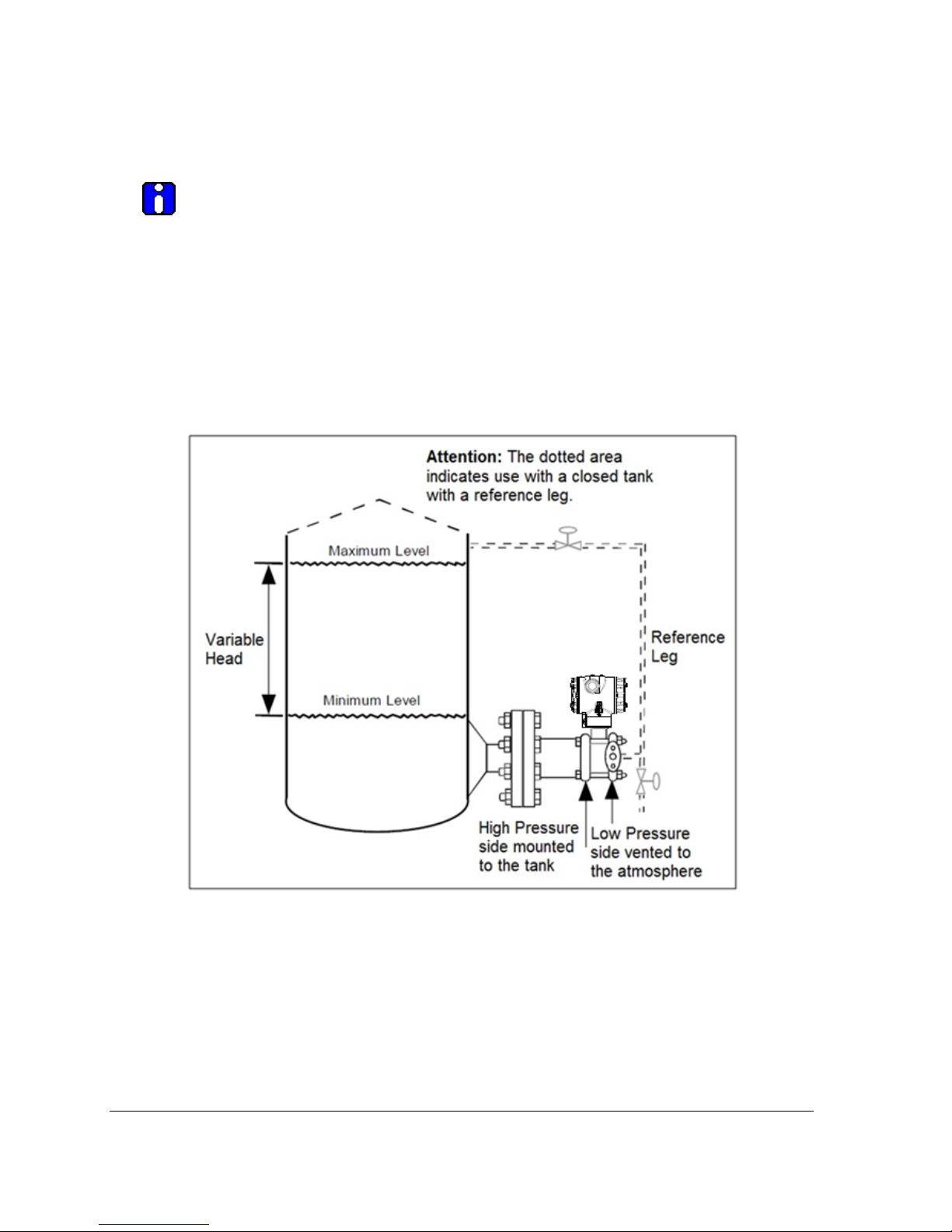
Figure 9 shows a typical tank-flange mount installation, with the Transmitter flange mounted to the
pipe on the wall of the tank.
On insulated tanks, remove enough insulaiton to accommodate the flange
extension.
When flange-mounting to a tank, note the following:
• The End User is responsible for providing a flange gasket and mounting hardware suitable for
the Transmitter service conditions.
• To avoid degrading performance in flush-mounted flanged Transmitters, exercise care to
ensure that the internal diameter of the flange gasket does not obstruct the sensing diaphragm.
• To prevent performance degradation in extended-mount flanged Transmitters, ensure that
sufficient clearance exists in front of the sensing diaphragm body.
Figure 9 – Tank-Flange Mounted Transmitter
Page 72 ST 700 SmartLine Pressure Transmitters User’s Manual Revision 1.0
Page 25
3.4.6 Remote Diaphragm Seal Mounting Information
The combination of tank vacuum and high pressure capillary head effect should not
exceed nine (9) psi (300 mmHg) absolute. For insulated tanks, be sure to remove enough
insulation to accommodate the flange extension. The end user is responsible for supplying a
flange gasket and mounting hardware suitable for the service condition of the Transmitter.
Mount the Transmitter flanges within the limits in Table 5 for the fill fluid in the capillary
tubes, with a tank at one (1) atmosphere.
Table 5 – Flange Mounting Guidelines
Fill Fluid Mount the Flange…
Silicone 200 Oil <22 feet (6.7 meters) below the Transmitter
Chlorotrifluorethylene (CTFE) <11 feet (3.4 meters) below the Transmitter
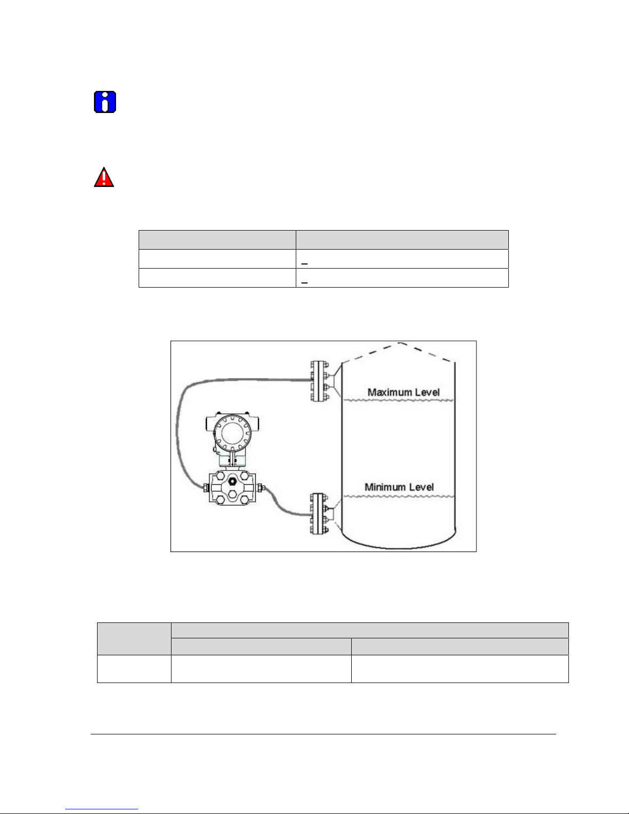
Refer to for a representative remote diaphragm seal installation. Mount the Transmitter at a remote
distance determined by the length of the capillary tubing.
Figure 10 – Representative Remote Diaphragm Seal Transmitter Installation
Depending on Transmitter model, connect the remote seal to the tank according to Table 6.
Transmitter
Model
STR73D
Transmitter High Pressure (HP) Side
to tank wall lower flange mounting.
Revision 2.0 ST 700 Smart Pressure Transmitter User’s Manual Page 13
Table 6 – Remote Diaphragm Mounting Details
Connect the Remote Seal on ….
Variable Head Fixed or Constant Head
Transmitter Low Pressure (LP) side to tank
wall upper flange.
Page 26
3.5 Piping the ST 700 Transmitter
3.5.1 Piping Arrangements
Piping arrangements vary depending upon process measurement requirements and the Transmitter
model. For example, a differential pressure transmitter comes with double-ended process heads with
¼-inch NPT connections, which can be modified to accept ½-inch NPT through optional flange
adapters. Gauge pressure transmitters are available with various connections for direct mounting to a
process pipe.
A ½-inch, schedule 80, steel pipe is commonly used for Transmitter integration into a process system.
Many piping arrangements use a three-valve manifold to connect the process piping to the
Transmitter. A manifold makes it easy to install and remove or re-zero a Transmitter without
interrupting the process. A manifold also accommodates the installation of blow-down valves to clear
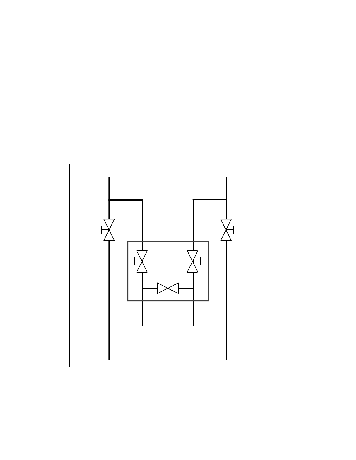
debris from pressure lines. Figure 11 represents a typical piping arrangement using a three-valve
manifold and blow-down lines for a differential pressure transmitter being used to measure flow.
To Upstream TapTo Downstream Tap
Blow-Down
Valve
Blow-Down
Piping
To Low Pressure
Side of Transmitter
Figure 11 – Typical 3-Valve Manifold with Blow-Down Piping
3-Valve
Manifold
To High Pressure
Side of Transmitter
Blow-Down
Piping
To WasteTo Waste
Blow-Down
Valve
Page 72 ST 700 SmartLine Pressure Transmitters User’s Manual Revision 1.0
Page 27

3.5.2 Suggestions for Transmitter Location
Suggests connections based on what is being processed by the system.
Table 7 – Suggested Connection Locations
Process Suggested Location Description
Gases Above the gas line. The condensate drains away from the Transmitter.
Liquids Below but near the elevation of
the process connection.
Level with or above the process
connection.
This minimizes that static head effect of the
condensate.
This requires a siphon to protect. the Transmitter from
process steam. The siphon retains water as a fill fluid.
1. For liquid or steam, the piping should slope a minimum of 25.4 mm (1 inch) per 305 mm (1 foot).
2. Slope the piping down toward the Transmitter if it is below the process connection to allow
the bubbles to rise back into the piping through the liquid.
3. If the transmitter is located above the process connection, the piping should rise vertically
above the Transmitter. In this case, slope down toward the flow line with a vent valve at the
high point.
4. For gas measurement, use a condensate leg and drain at the low point (freeze protection may
be required here).
3.5.3 General Piping Guidelines
• When measuring fluids that contain suspended solids, install permanent valves at regular
intervals to blow-down piping.
• Blow-down all lines on new installations with compressed air or steam, and flush them with
process fluids (where possible) before connecting these lines to the Transmitter Meter body.
• Verify that the valves in the blow-down lines are closed tightly after the initial blow-down
procedure and each maintenance procedure thereafter.
3.5.4 Procedure to Install Flange Adapters
The following procedure provides the steps for removing and replacing an optional flange adapter on
the process head.
This procedure does not require that the Meter body be removed from the
Electronics Housing. If flange adapters are being replaced with parts from other
kits (for example, process heads), follow the procedures for the kits and
incorporate the following procedure.
NOTE: The threaded hole in each Flange Adapter is offset from center. To ensure
proper orientation for re-assembly, note the orientation of the offset relative to each
Process Head before removing any adapter.
Revision 2.0 ST 700 Smart Pressure Transmitter User’s Manual Page 15
Page 28
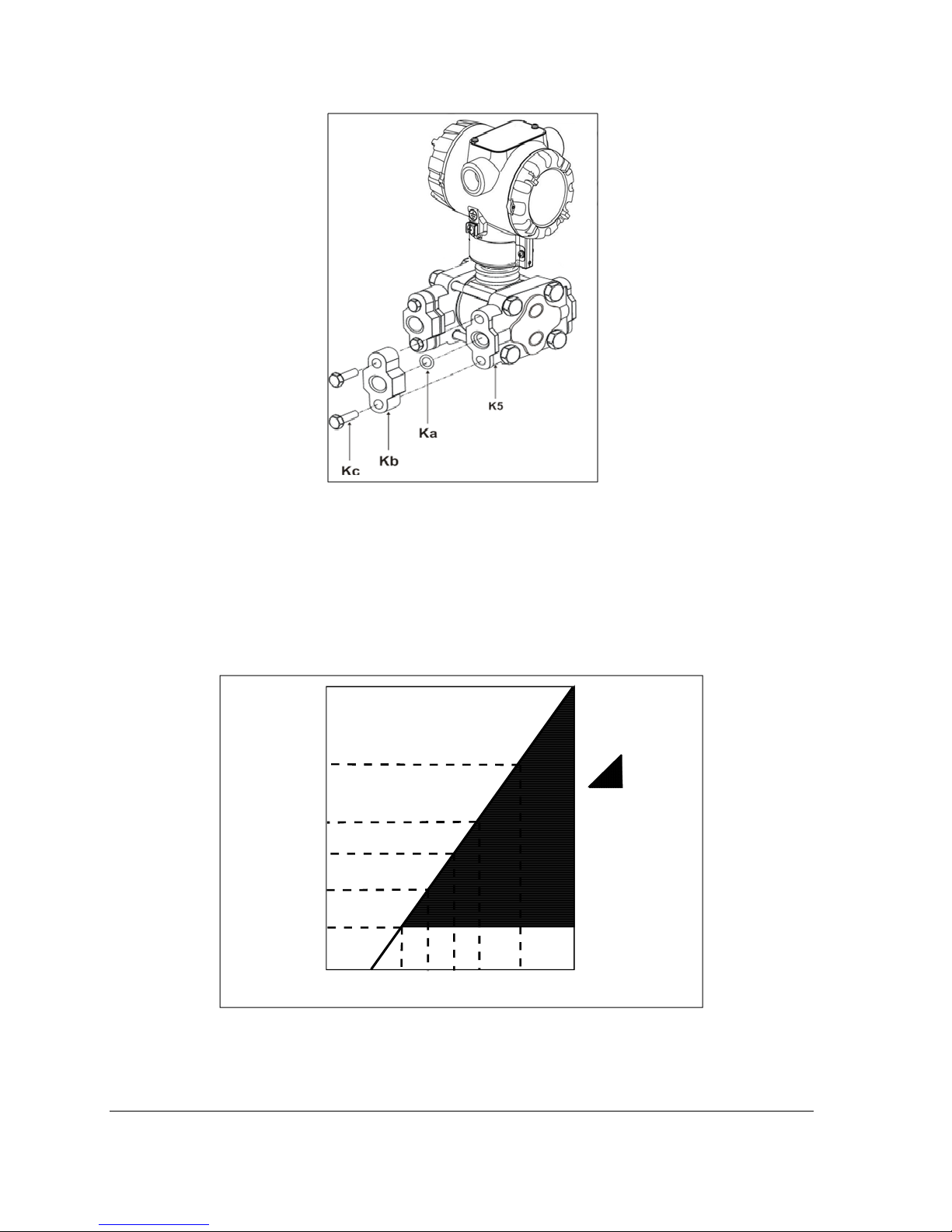
Figure 12 – Flange Adapter Removal and Replacement
Refer to the instructions included with the kit for removal and replacement procedures.
3.6 Wiring a Transmitter
3.6.1 Overview
The transmitter is designed to operate in a two-wire power/current loop with loop resistance and
power supply voltage within the operating range shown in Figure 13.
1440
Loop
Resistance
(ohms)
1200
800
650
450
250
= Operating
Area
NOTE: A minimum of
250 0hms of loop
resistance is
necessary to supp or t
communications. Loop
resistance equals
barrier resistance plus
wire resistance plus
receiver resistance.
Also 45 volt operation
is permitted if not an
intrinsically safe
installation.
Figure 13 – Transmitter Operating Ranges
Loop wiring is connected to the Transmitter by simply attaching the positive (+) and negative (–) loop
wires to the positive (+) and negative (–) terminals on the Transmitter terminal block in the
Electronics Housing shown in Figure 14.
Page 72 ST 700 SmartLine Pressure Transmitters User’s Manual Revision 1.0
0 10.8 16.28 20.63 25 28.3 37.0 42.4
Operating Voltage (Vdc)
21012
Page 29
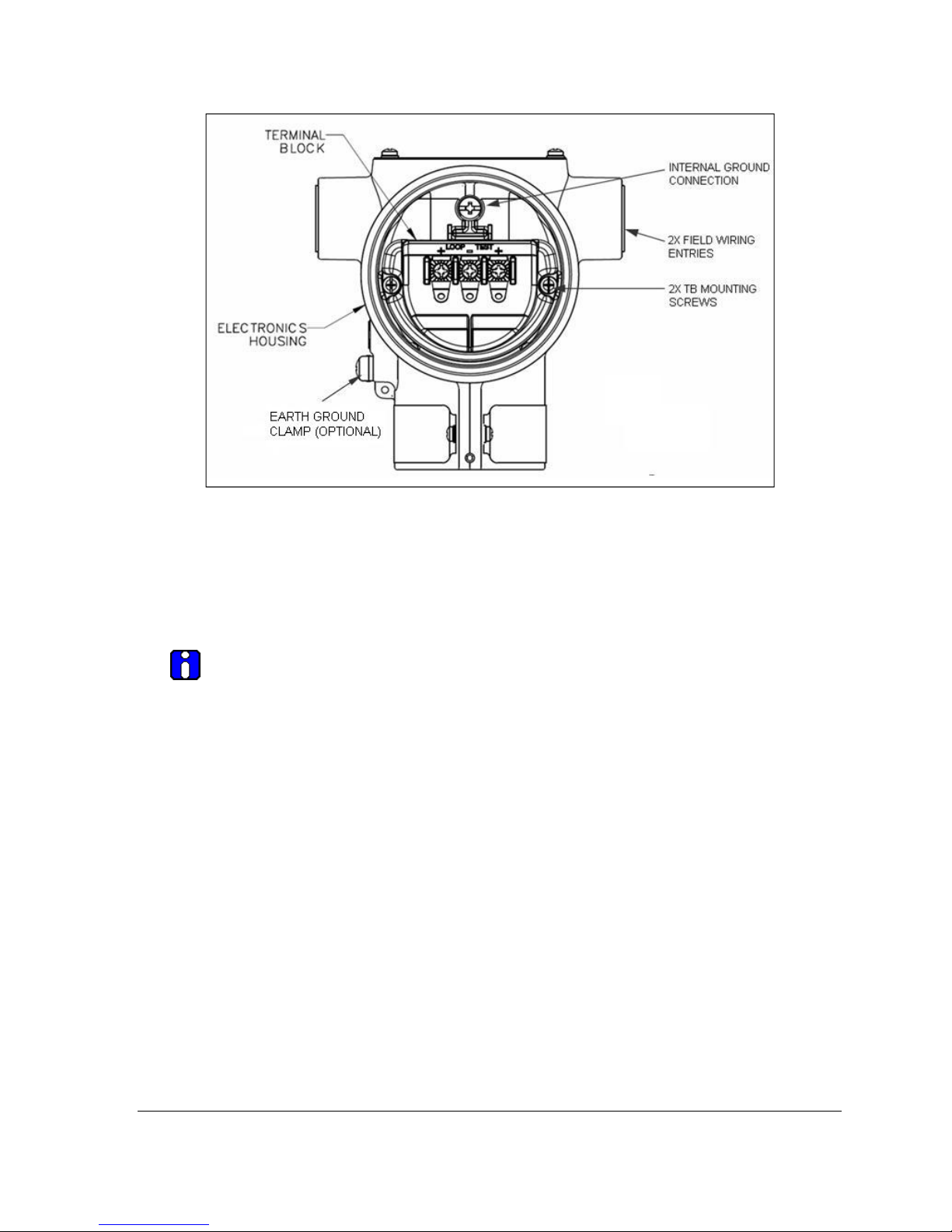
Figure 14 – Transmitter 3-Screw Terminal Board and Grounding Screw
As shown in Figure 14, each Transmitter has an internal terminal to connect it to earth ground.
Optionally, a ground terminal can be added to the outside of the Electronics Housing. While it is not
necessary to ground the Transmitter for proper operation, doing so tends to minimize the possible
effects of noise on the output signal and affords protection against lightning and static discharge. An
optional lightning terminal block can be installed in place of the non-lightning terminal block for
Transmitters that will be installed in an area that is highly susceptible to lightning strikes.
Wiring must comply with local codes, regulations and ordinances. Grounding may
be required to meet various approval body certification, for example CE conformity.
Refer to Appendix A of this document for details.
Note: The right hand terminal is for loop test and not applicable for Fieldbus option.
The Transmitter is designed to operate in a two-wire power/current loop with loop resistance and
power supply voltage within the operating range; see Figure 13. With optional lightning protection
and/or a remote meter, the voltage drop for these options must be added to the basic 10.8-volt supply
requirements to determine the required Transmitter voltage (V
(R
LOOP MAX
they will supply at least minimum Transmitter voltage (V
). Additional consideration is required when selecting intrinsic safety barriers to ensure that
XMTR MIN
) and maximum loop resistance
XMTR
), including the required 250 ohms
of resistance (typically within the barriers) needed for digital communications.
Transmitter loop parameters are as follows:
R
LOOP MAX
operation and is calculated as R
= maximum loop resistance (barriers plus wiring) that will allow proper Transmitter
LOOP MAX
= (V
SUPPLY MIN
– V
XMTR MIN
) ÷ 21.8 mA.
In this calculation:
V
XMTR MIN
= 10.8 V + VLP + V
SM
VLP = 1.1 V, lightning protection option, LP
V
= 2.3 V, remote meter
SM
Revision 2.0 ST 700 Smart Pressure Transmitter User’s Manual Page 17
Page 30

Note that V
should only be considered if a remote meter will be connected to the transmitter.
SM
The positive and negative loop wires are connected to the positive (+) and negative (–) terminals on
the terminal block in the Transmitter Electronics Housing.
Barriers can be installed per Honeywell’s instructions for Transmitters to be used in intrinsically safe
applications.
3.6.2 Digital System Integration Information
Transmitters that are to be digitally integrated to Honeywell’s Total Plant Solution (TPS) system will
be connected to the Pressure Transmitter Interface Module in the Process Manager, Advanced
Process Manager or High Performance Process Manager through a Field Termination Assembly.
Details about the TPS system connections are given in the PM/APM SmartLine Transmitter
Integration Manual, PM12-410, which is part of the TDC 3000
X
system bookset.
If you are digitally integrating a Transmitter in an Allen Bradley Programmable Logic Controller
(PLC) process system, the same Field Terminal Assembly (FTA) and wiring procedures used with
Honeywell’s TPS system are also used with the Allen-Bradley 1771 and 1746 platforms.
3.6.3 Wiring Variations
The above procedures are used to connect power to a Transmitter. For loop wiring and external
wiring, detailed drawings are provided for Transmitter installation in non-intrinsically safe areas and
for intrinsically safe loops in hazardous area locations.
If you are using the Transmitter with Honeywell’s TPS system, see PM/APM Smartline Transmitter
Integration Manual, PM12-410, which is part of the TDC 3000
X
system bookset.
3.6.4 Wiring Procedure
1. See Figure 14, above, for parts locations. Loosen the end cap lock using a 1.5 mm Allen wrench.
2. Remove the end cap cover from the terminal block end of the Electronics Housing.
3. Feed loop power leads through one end of the conduit entrances on either side of the
Electronics Housing. The Transmitter accepts up to 16 AWG wire.
4. Plug the unused conduit entrance with the appropriate plug for the environment.
5. Connect the positive loop power lead to the positive (+) terminal and the negative loop power
lead to the negative (-) terminal. Note that the Transmitter is not
polarity-sensitive.
6. Replace the end cap, and secure it in place.
3.6.5 Lightning Protection
If your Transmitter includes the optional lightning protection, connect a wire from the Earth Ground
Clamp (see Figure 14) to Earth Ground to make the protection effective. Use a size 8 AWG or
(8.37mm
2
) bare or green covered wire for this connection.
3.6.6 Supply Voltage Limiting Requirements
If your Transmitter complies with the ATEX 4 directive for self-declared approval per 94/9EC, the
power supply has to include a voltage-limiting device. Voltage must be limited such that it does not
exceed 42 V DC. Consult the process design system documentation for specifics.
Page 72 ST 700 SmartLine Pressure Transmitters User’s Manual Revision 1.0
Page 31

3.6.7 Process Sealing
The ST 700 SmartLine Pressure Transmitter is CSA-certified as a Dual Seal device in accordance
with ANSI/ISA–12.27.01–2003, “Requirements for Process Sealing Between Electrical Systems and
Flammable, or Combustible Process Fluids.”
3.6.8 Explosion-Proof Conduit Seal
When installed as explosion proof in a Division 1 Hazardous Location, keep covers
tight while the Transmitter is energized. Disconnect power to the Transmitter in the
non-hazardous area prior to removing end caps for service.
When installed as non-incendive equipment in a Division 2 hazardous location,
disconnect power to the Transmitter in the non-hazardous area, or determine that the
location is non-hazardous before disconnecting or connecting the Transmitter wires.
Transmitters installed as explosion proof in Class I, Division 1, Group A Hazardous (classified)
locations in accordance with ANSI/NFPA 70, the US National Electrical Code, with 1/2 inch conduit
do not require an explosion-proof seal for installation. If 3/4 inch conduit is used, a LISTED
explosion proof seal to be installed in the conduit, within 18 inches (457.2 mm) of the Transmitter.
3.7 Startup
3.7.1 Overview
This section identifies typical start up tasks associated with several generic pressure measurement
applications. It also includes the procedure for running an optional analog output check.
Startup Tasks
After completing the installation and configuration tasks for a Transmitter, you are ready to start up the
process loop. Startup usually includes:
• Checking zero input
• Reading inputs and outputs
• Applying process pressure to the transmitter.
You can also run an optional output check to wring out an analog loop and check out individual
Process Variable (PV) outputs in Digitally Enhanced (DE) mode before startup.
The actual steps in a startup procedure vary based on the type of Transmitter and the measurement
application. In general, the procedures in this section are based on using Honeywell MC Toolkit to
check the Transmitter input and output under static process conditions, and make adjustments as
required initiating full operation with the running process. Note that like checks can be made using
the optional three-button assembly, if your Transmitter is so equipped. Operation with the threebutton assembly is discussed in the “Operation” section of this manual.
Revision 2.0 ST 700 Smart Pressure Transmitter User’s Manual Page 19
Page 32
3.7.3 Output Check Procedures
The Output Check comprises the following procedures:
• The Loop Test procedure checks for continuity and the condition of components in the output
current loop.
• The Trim DAC Current procedure calibrates the output of the Digital-to-Analog converter for
minimum (0%) and maximum (100%) values of 4 mA and 20 mA, respectively. This
procedure is used for Transmitters operating online in analog mode to ensure proper
operation with associated circuit components (for example, wiring, power supply,…, control
equipment). Precision test equipment (an ammeter or a voltmeter in parallel with precision
resistor) is required for the Trim DAC Current procedure.
• The Apply Values procedure uses actual Process Variable (PV) input levels for calibrating
the range of a Transmitter. To measure a liquid level for example, a sight-glass can be used to
determine the minimum (0%) and maximum (100%) level in a vessel. The PV is carefully
adjusted to stable minimum and maximum levels, and the Lower Range Limit Value (LRV)
and Upper Range Limit Value (URV) are then set by commands from the MC Toolkit.
The Transmitter does not measure the given PV input or update the PV output while
it operates in the Output mode.
3.7.4 Constant Current Source Mode Procedure
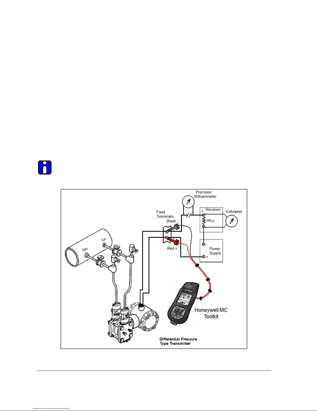
Figure 15 – Current Loop Test Connections
Page 72 ST 700 SmartLine Pressure Transmitters User’s Manual Revision 1.0
Page 33

1. Refer to Figure 15 for test connections. Verify the integrity of electrical components in the output
current loop.
2. Establish communication with the Transmitter. For these procedures, the values of components in
the current loop are not critical if they support reliable communication between the Transmitter
and the Toolkit.
3. On the Toolkit, display the Output Calibration box.
4. In the Output Calibration box, select the Loop Test button; the LOOP TEST box will be
displayed.
5. Select the desired constant-level Output: 0 %, 100 %, or Other (any between 0 % - 100 %).
6. Select the Set button. A box will be displayed asking Are you sure you want to place the
transmitter in output mode?
With the Transmitter in Analog mode, you can observe the output on an externally-
connected meter or on a local meter. In DE mode, you can observe the output on
the local meter or on the Toolkit Monitor display.
7. Select the Yes button. Observe the output current at the percentage you selected in Step 5.
8. To view the monitor display, navigate back from the LOOP TEST display, and select the
MONITOR display. A Confirm popup will be displayed.
9. Select Yes to continue. This concludes the Startup procedure.
Revision 2.0 ST 700 Smart Pressure Transmitter User’s Manual Page 21
Page 34
4 Operation
4.1 Overview
This section provides the information and processes involved for both Digitally Enhanced (DE) and
HART operation using the 3-button option.
4.2 Three-Button Operation
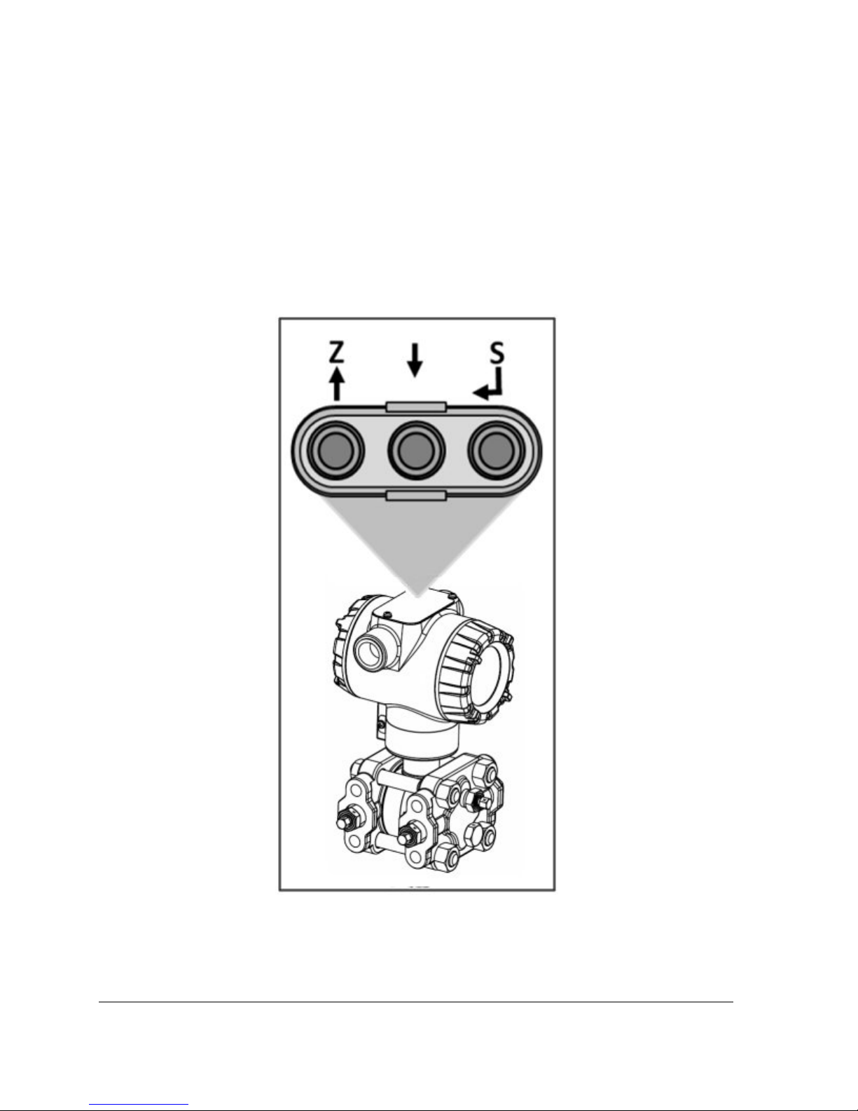
The ST 700 optional three-button interface provides a user interface and operation capability without
opening the transmitter. Figure 16 shows the location of the three-button option and the labels for
each button.
Page 72 ST 700 SmartLine Pressure Transmitters User’s Manual Revision 1.0
Figure 16 – Three-Button Option
Page 35

Table 8 – Three-Button Option Functions
Physical
Button
Left
Center
Right
↵
Basic Display Action
Increment
Previous Menu Item
Decrement
Next Menu Item
Select displayed
menu item for
activation or editing
Scroll to previous menu item in an active list.
Scroll through alphanumeric list to desired
character (ex. for entering Tag names or
numeric values)
Scroll to next menu item in an active list.
Scroll through alphanumeric list to desired
character (ex. for entering Tag names or
numeric values)
Call up the Main Menu.
Select an item for data entry.
Confirm a data entry operation
Activate the service associated with a
selected menu item.
4.2.1 The Basic Display Menu
The Basic Display Menu is implemented as one long single-level menu and will “wrap around” when
it reaches the start or end of the menu. Operation is as follows:
Press the
↵ button to call up the Menu.
1. Select <Exit Menu> and press
↵ to exit the Menu.
2. Use the and buttons to scroll through the list of menu items.
3. Press the ↵ button to select an item for data entry or activation. When an item is selected for
data entry or activation, the cursor will jump to the lower line of the LCD to allow editing of
the value. No action is taken against a menu item until the user presses the
↵ button.
4. If you want to abort a data entry operation, simply refrain from pushing any buttons for 10
seconds; the data entry operation will time out and the original value of the selected item will
be preserved.
Table 9 – The Basic Display Menus
Press ↵ to
enter menu
selection
↑ and ↓ to
select level.
↵ to enter
Press ↵ to
enter menu
selection
↑ and ↓ to
select from
list
LCD Contrast »»»»»
Pressure Pressure Units Select Process
PV Display
PV Decimal
Percent Output %
Loop Output mA
None
X.X
X.XX
X.XXX
Adjust the LCD contrast level.
Range from » (1) to »»»»»»»»»
(9)
Default: »»»»»»»(7)
Variable (PV) to
be shown on the
display from list.
Select the PV decimal resolution to
be shown on selected screen from
list.
Revision 2.0 ST 700 Smart Pressure Transmitter User’s Manual Page 23
Page 36

atm, bar
ftH2O @ 68ºF
gf/cm2
inH2O @ 39ºF
inH2O @ 60ºF
inH2O @ 68ºF
inHg @ 0ºC
kgf/cm2, kPa
mbar,
Pressure Units
mmH2O @ 4ºC,
mmH2O @ 68ºF,
mmHg @ 0ºC,
MPa, Pa,
psi
Torr,
mH2O @ 4ºC
mHg @ 0ºC
Zero Correct Do Correct
LRV Correct Do Correct
URV Correct Do Correct
Reset Corrects Do Correct
DAC Zero Trim
Note: Loop must be
DAC Zero Trim
removed from
Automatic Control
DAC Span Trim
Note: Loop must be
DAC Span Trim
removed from
Automatic Control
Loop Test
Note: Loop must be
removed from
Loop Test
12.000
Automatic Control
Choose appropriate engineering
units from list
Executing this selection corrects the
Zero based on the input pressure
Executing this selection corrects the
LRV based on the input pressure
Executing this selection corrects the
LRV based on the input pressure
Executing this selection Resets the
Zero, LRV, and URV Corrects back
to Factory values
This selection allows the loop zero
output 4mA value to be trimmed.
Note: You must connect a current
meter to the transmitter to monitor
the loop output.
This selection allows the loop span
output 20mA value to be trimmed.
Note: You must connect a current
meter to the transmitter to monitor
the loop output.
This selection allows the user to
force the DAC output to any value
between 3.8 and 20.8 mA.
Note: This selection will put the DAC
into Fixed Output Mode, as
indicated by the flashing output
value. Navigation away from this
menu item will return the loop to
Normal (Automatic) Mode.
↵ to enter
Press ↵ to
enter menu
selection
Press ↵ to
initiate action
Press ↵ to
enter menu
selection
↑ and ↓ to
select
number.
↵ to enter
and shift to
the next digit
to the right
Page 72 ST 700 SmartLine Pressure Transmitters User’s Manual Revision 1.0
Page 37

LRV
URV
#. ##
#. ##
Damping #. ##
NAMUR
Enabled
Disabled
Filter Perf
Fast SOR
Standard SOR
Linear
Transfer Function
(only available for
DP Transmitters)
Square Root
Single Breakpt
Flow Cutoff
Dual Slope
Flow Breakpoint ##. #%
The limits are:
2X the Lower Range Limit (LRL) of
the Meter body and 2X the Upper
Range Limit (URL) of the Meter
body
Selection applies digital filtering to
suppress noise effects on the PV.
The limits for this value are 0.0 to
32.0 seconds
Disabling sets the loop output and
burnout levels to the Honeywell
levels
Fast Speed of Response
Standard Speed of Response
The loop output of the transmitter is
a linear representation of the
differential pressure
The loop output of the transmitter
represents %Flow as defined by the
DP Square Root flow equation.
Allows the user to specify a single
breakpoint as the low flow cutoff
point.
This item is only available when the
Transfer Function is set to Square
Root.
Uses a dual slope formula to
determine the low flow cutoff point.
This item is only available when the
Transfer Function is set to Square
Root.
Enter the low flow cutoff point when
Single Breakpt is selected. Range: 0
to 25.0 %Flow.
Press ↵ to
enter menu
selection
↑ and ↓ to
select
number.
↵ to enter
and shift to
the next digit
to the right
Press ↵ to
enter menu
selection
↑ and ↓ to
select from
list
↵ to enter
Press ↵ to
enter menu
selection
↑ and ↓ to
select
Alphanumeric
↵ to enter
and shift to
next
character to
the right.
Revision 2.0 ST 700 Smart Pressure Transmitter User’s Manual Page 25
Page 38

Tag ID
Install Date DD MM YYYY
Firmware
Protocol
Model Key
<Exit Menu>
Display
Electronics
Meterbody
HART
DE
Enter Tag ID name up to 8
characters long.
= any Alphanumeric value
This selection allows the user to
enter the date a transmitter is
installed.
The Install Date is entered in
sequence of Day, Month, and Year,
followed by the new date and the
prompt Write Date to confirm the
entry.
CAUTION
be written once in the life of the
Transmitter. You cannot erase or
overwrite the Install Date once it has
been written.
Menu item shows the current
Firmware versions of the Display,
Electronics Module and the Meter
body
Menu item shows the
communications protocol
Identifies the type and range of the
transmitter
: The Install Date can only
Press ↵ to
enter menu
selection
↑ and ↓ to
select
Alphanumeric
↵ to enter
and shift to
next
character to
the right.
Press ↵ to
enter menu
selection
↑ and ↓ to
select
number
↵ to enter
and shift to
next digit to
the right.
Read Only
after entered
Read Only
Parameter
Read Only
Parameter
Page 72 ST 700 SmartLine Pressure Transmitters User’s Manual Revision 1.0
Page 39

4.2.2 Data Entry
Data entry is performed from left to right. Select a character / digit by pressing or buttons, and
then press
to terminate the entry or if the final character is already a space character, just press << again.
All numeric entries are clamped at the low or high limit if needed. You can determine the low and
high limit for a parameter by selecting either the
the left-most digit and press
↵ to advance to the next character position to the right. Select the cross-hatch character ▒
H or L character while the cursor is positioned over
↵ button. The Display will show the selected limit.
Table 10 – Three-Button Data Entry
Screen
Symbol
H
L
Display the high limit for this parameter.
This symbol only appears in the left-most
position of the data entry field.
Display the low limit for this parameter.
This symbol only appears in the left-most
position of the data entry field.
Numeric data entry Text entry
Not Available
Not Available
<<
0 thru 9,
Minus,
Decimal
A thru Z,
0 thru 9
special
symbols
Terminate the numeric entry Terminate the text entry
These characters are used to enter
numeric values. The minus sign only
appears in the left-most digit.
Not Available
These characters can be used to
enter the Tag ID
These characters can be used to
enter the Tag ID
4.2.3 Editing a Numeric value
Editing of a numeric value is a digit-by-digit process, starting with the left-most digit.
1. Press
2. The Basic Display will show the current value of the item on the lower line, left justified. The
3. Press the or buttons to select the desired digit, and then press
4. After the last digit has been entered, press ↵ one more time to write the new value to the
↵ to begin the edit process.
↵ to advance to the next
digit to the right.
transmitter.
4.2.4 Selecting a new setting from a list of choices
Use the procedure described below to select a new setting for parameters that present a list of choices
(e.g., PV Display, Pressure Units, etc.).
1. Press
2. Press the or buttons to scroll through the list of choices.
↵ to make your selection. The new selection will be stored in the transmitter and will be
Press
displayed on the lower line, right justified.
Revision 2.0 ST 700 Smart Pressure Transmitter User’s Manual Page 27
↵ to begin the edit process.
a. The Basic Display will show the current setting of the item on the lower line, left
justified.
Page 40

4.3 Three Button Operation with no Display Installed
When there is no Display installed, the buttons can be used to perform a Zero or Span adjustment of
the Transmitter. Caution should be taken to insure these adjustments are only made when the correct
input pressures are applied.
4.3.1 Zero Adjustment
This adjustment is the same as performing a Set LRV using the Display.
1. Connect a current meter or voltmeter as shown in Figure 15 to monitor the PV output of the
Transmitter.
2. Using an accurate pressure source, apply pressure equivalent to the Transmitter LRV.
3. Press the Down (
4. Verify that the output is now 4 mA.
↓ ) and Zero ( ↑ ) buttons together to set the Zero.
4.3.2 Span Adjustment
This adjustment is the same as performing a Set URV using the Display.
1. Connect a current meter or voltmeter as shown in Figure 15 to monitor the PV output of the
Transmitter.
2. Using an accurate pressure source, apply pressure equivalent to the desired Upper Range
Value of the transmitter.
3. Press the Down (
4. Verify that the PV output is now 20 mA.
You can also use the MCT 202 Toolkit to make any adjustments to an ST 700
SmartLine Pressure Transmitter. Alternately, certain adjustments are possible
through an Experion Station or Universal Station, if the ST 700 is digitally
integrated with either of these stations.
↓) and Span ( ) buttons together to set the span.
4.4 Changing the Default Failsafe Direction
Transmitters are shipped with a default failsafe direction of upscale. This means that the Transmitter
output will set the current output to upscale failsafe (maximum output) upon detection of a critical
status. You can change the direction from upscale failsafe to downscale failsafe (minimum output) by
moving the top jumper located in the Electronics module.
4.4.1 DE and Analog Differences
Failsafe operation is somewhat different between DE and analog operation:
• Analog operation – Upscale failsafe drives the Transmitter output to 21.8 mA. Downscale
failsafe drives the Transmitter output to 3.8 mA.
• DE operation – Upscale failsafe causes the Transmitter to generate a + infinity digital
signal. Downscale failsafe causes the Transmitter to generate a – infinity digital signal.
The Transmitter electronics module interprets either signal as not-a-number and initiates its own
configured failsafe action for the control system.
Page 72 ST 700 SmartLine Pressure Transmitters User’s Manual Revision 1.0
Page 41
4.4.2 Procedure to Establish Failsafe Operation
The failsafe direction display accessible via the Toolkit shows only the state of the
jumper as it correlates to analog Transmitter operation. Failsafe action for the DE
control system may be configured to operate in a manner different from analog, as
indicated by the state of the Transmitter jumper.
The integrated circuits in the Transmitter PWA are vunerable to damage by stray
static discharges when removed from the Electronics Housing. Minimize the possibility of
static discharge damage when handling the PWA as follows:
Do not touch terminals, connectors, component leads, or circuits when handling the
PWA.
When removing or installing the PWA, handle it by its edges or bracket section only. If
you need to touch the PWA circuits, be sure you are grounded by staying in contact with
a grounded surface or by wearing a grounded wrist strap.
When the PWA is removed from the Transmitter, put it in an electrically conductive bag,
or wrap it in aluminum foil to protect it.
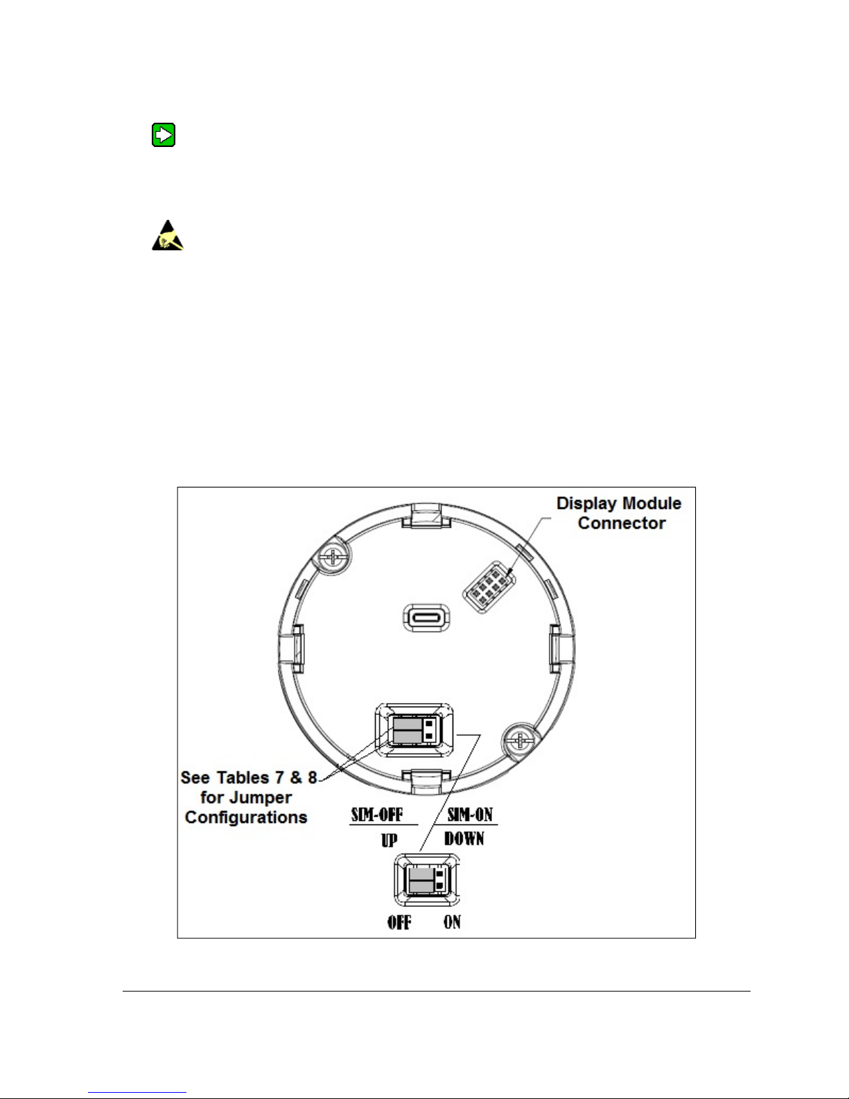
The following procedure outlines the steps for positioning the write protect and failsafe jumpers on
the electronics module. See Figure 17 for the locations of the failsafe and write protect jumpers.
Figure 17 – Locating the Failsafe and Write Protect Jumpers
Revision 2.0 ST 700 Smart Pressure Transmitter User’s Manual Page 29
Page 42
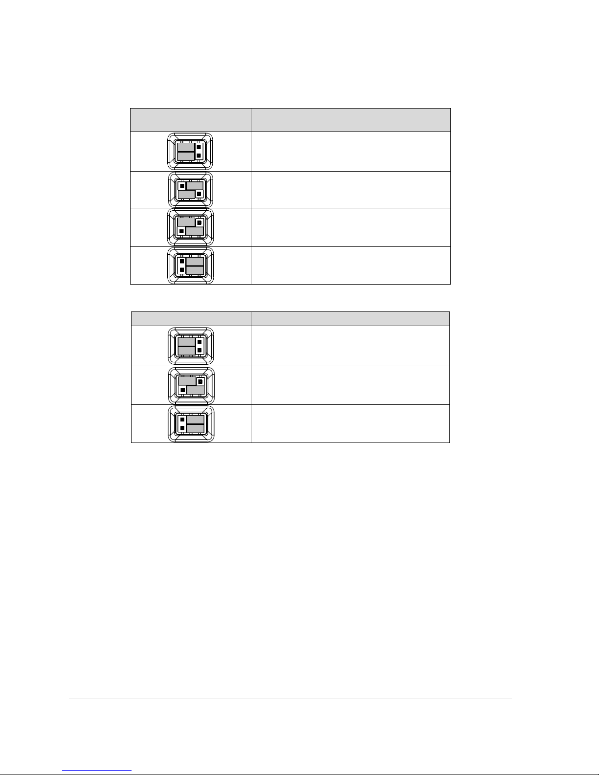
Table 11 – Hart and DE Failsafe and Write Protect Jumpers
Jumper
Arrangements
Description
Failsafe = UP (High)
Write Protect = OFF (Not Protected)
Failsafe = DOWN (Low)
Write Protect = OFF (Not Protected)
Failsafe = UP (High)
Write Protect = ON (Protected)
Failsafe = Down (Low)
Write Protect = On (Protected)
Table 12 – Fieldbus Simulation and Write Protect Jumpers
Image Description
Fieldbus Simulation Mode = OFF
Write Protect = OFF (Not Protected)
Fieldbus Simulation Mode = OFF
Write Protect = ON (Protected)
Fieldbus SIM Mode = ON
Write Protect = OFF (Not Protected)
1. Turn OFF Transmitter power (Power removal is only required in accordance with area safety
approvals. Power removal is only required in Class 1 Div 1 Explosionproof and Class 1 Div
2 environments).
2. Loosen the end cap lock, and unscrew the end cap from the electronics side of the Transmitter
housing.
3. If equipped with a Display module, carefully depress the two tabs on the sides of the Display
Module, and pull it off.
4. If necessary, unplug the interface connector from the Communication module. Do not discard
the connector.
5. Set the Failsafe Jumper (top jumper) to the desired position (UP or DOWN). See Table 11
and Table 12 for jumper positioning.
6. If applicable, re-install the Display module as follows:
• Orient the display as desired.
Page 72 ST 700 SmartLine Pressure Transmitters User’s Manual Revision 1.0
Page 43

• Install the Interface Connector in the Display module such that it will mate
with the socket for the display in the Communication module.
• Carefully line up the display, and snap it into place. Verify that the two tabs
on the sides of the display latch.
NOTE: Installing a Display Module into a powered transmitter may cause a temporary upset
to the loop output value.
Orient the Display for proper viewing through the end cap window.
You can rotate the meter mounting orientation in 90 o increments.
7. Restore transmitter power if removed.
Revision 2.0 ST 700 Smart Pressure Transmitter User’s Manual Page 31
Page 44
4.5 Monitoring the Basic Display
This section describes the information shown on the operator screens of the Basic Display.
4.5.1 Basic Display
Figure 18 illustrates the Basic Display format with Process Variable (PV).
• The PV value is user-configurable. This field has 7 characters. The maximum allowable
numeric value is 9999999 or -999999. If fractional decimals are configured, the fractional
positions will be dropped, as required. If the PV value exceeds the above limits, it is divided
by 1000 and “K” is appended to the result, allowing a maximum value with multiplier of
999999K or -99999K.
• Process Variable Tag is user-configurable from a HART Host. This field has 14 characters.
• Engineering Units. This field is user-configurable. This field has 8 characters.
Figure 18 – Basic Display with Process Variable Format
Page 72 ST 700 SmartLine Pressure Transmitters User’s Manual Revision 1.0
Page 45

5 Maintenance
5.1 Overview
This section provides information about preventive maintenance and replacing damaged parts. The
topics covered in this section are:
• Preventive maintenance of the meter body barrier diaphragms and process piping to the
Transmitter.
• Replacement of damaged parts such as the Transmitter Printed Wiring Assembly (PWA) and
meter body
5.2 Preventive Maintenance Practices and Schedules
The ST 700 Transmitter does not require any specific maintenance at regularly scheduled intervals.
However, it is recommended that you perform these typical inspection and maintenance routines on a
schedule that is dictated by the characteristics of the process medium and if blow-down facilities or
purge systems are being used.
• Check piping for leaks.
• Clear piping of sediment or other foreign matter.
• Clean the Transmitter process heads, including the barrier diaphragms.
5.3 Inspecting and Cleaning Barrier Diaphragms
Depending on the characteristics of the process medium, sediment or other foreign particles may
collect in the process head cavity/chamber and cause faulty measurement. In addition, the barrier
diaphragm(s) in the Transmitter meter body may become coated with residue from the process
medium. The latter is also true for external diaphragms on flange-mount and remote seal type
Transmitters.
In many cases, you can readily remove the process head(s) from the Transmitter meter body to clean
the process head cavity and inspect the barrier diaphragm(s). For flange-mount and remote seal
diaphragms, you may only need to run a purge line in the tank to rinse off the face of the
diaphragm(s).
The following procedure comprises the general steps for inspecting and cleaning barrier diaphragms.
You may have to modify these steps to meet your particular process or transmitter model
requirements. Figure 19 shows an exploded view of a Differential Pressure (DP) Transmitter meter
body for reference. For disassembly/reassembly purposes, Gauge Pressure (GP) and Absolute
Pressure (AP) Transmitters are similar.
It is recommended that you remove the Transmitter from service and move it to a
clean area before disassembling it.
Revision 2.0 ST 700 Smart Pressure Transmitter User’s Manual Page 33
Page 46
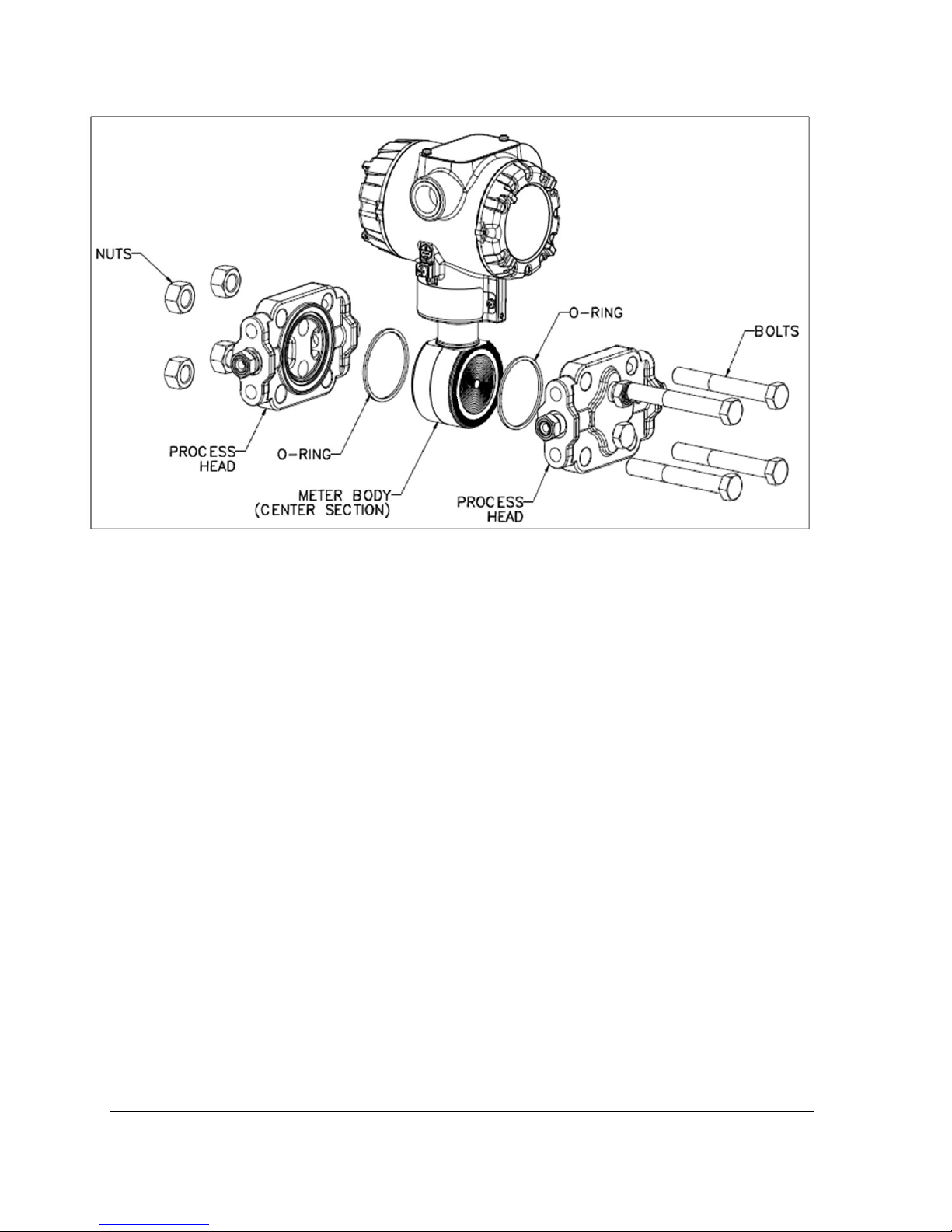
Figure 19 – DP Transmitter Head Disassembly
1. Close all valves to isolate the Transmitter from the process.
2. Open the vent in the process head to drain fluid from the Transmitter meter body, as
necessary.
3. Remove the Transmitter from the process.
4. Loosen the nuts in the sequence shown in Figure 20.
5. Remove the nuts from the bolts that hold the process head(s) to the meter body.
6. Remove the process heads and bolts.
7. Remove the gasket/ O-ring, and clean the interior of the process head using a soft bristle
brush and an approved solvent.
8. Inspect the barrier diaphragm for signs of deterioration, corrosion, and distortion.
9. If the diaphragm is distorted contact Honeywell for assistance.
10. Install a new gasket/O-ring in each process head.
11. Coat threads on the process head bolts with a suitable anti-seize compound, such as
“Neverseize,” or equivalent.
12. Using a torque wrench, gradually tighten the nuts in the sequence shown in Figure 20.
Tighten head bolts in stages of 1/3-full torque, 2/3-full torque, and full torque. See Table 13
for torque requirements versus Transmitter type and model.
Page 72 ST 700 SmartLine Pressure Transmitters User’s Manual Revision 1.0
Page 47
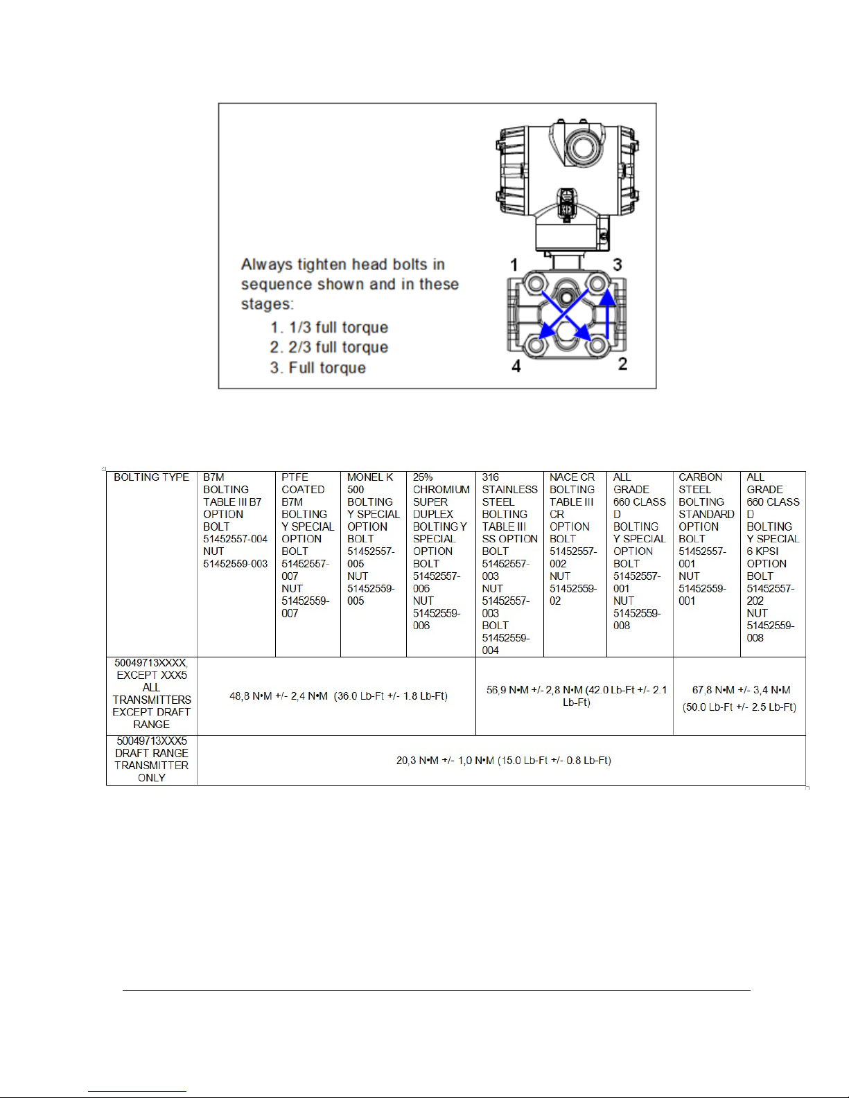
Figure 20 – Head Bolt Tightening Sequence
Table 13 – Head Bolt Torque Values
Revision 2.0 ST 700 Smart Pressure Transmitter User’s Manual Page 35
Page 48
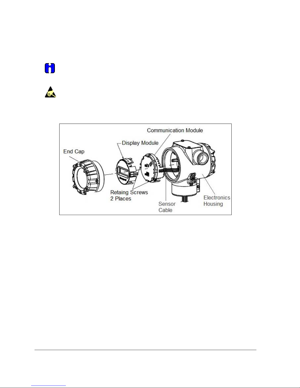
5.4 Replacing the Communication Module
The Communication module includes a connector to the sensor ribbon cable and a connector to the
optional Display module. This section includes the procedure to replace the Communication module.
The transmitter does not have to be removed from service to replace the Comm Module
Please take appropriate steps to avoid ESD damage when handling the
Communication and Display Module assemblies
Refer to Figure 21 for parts locations.
Figure 21 – PWA Replacement
1. Turn OFF Transmitter power (Power removal is only required in accordance with area safety
approvals. Power removal is only required in Class 1 Div 1 Explosionproof and Class 1 Div
2 environments).
• When removing the Communications Module with power applied, the loop will go to
0V. Likewise, installing a Communications Module into a transmitter with power
applied will cause the loop output value to go to 12 ma for several seconds then the
loop output value will go to the configured value based on the PV input.
• Installing a Display Module into a powered transmitter may cause a temporary upset
to the loop output value.
2. Loosen the end cap lock, and unscrew the end cap from the electronics side of the Transmitter
housing.
3. If equipped with a Display module, carefully depress the two tabs on the sides of the Display
Module, and pull it off.
Page 72 ST 700 SmartLine Pressure Transmitters User’s Manual Revision 1.0
Page 49

4. If necessary, unplug the interface connector from the Communication module. Do not
discard the connector.
5. Loosen the two retaining screws, and carefully pull the Communication module from the
Electronics compartment.
6. Carefully align and connect the Sensor Ribbon Cable to the connector “J4” at the bottom of
the Communication module. When installing the Communication module in the next step, be
careful not to pinch the Sensor Ribbon Cable.
7. Carefully, insert the Communication module into the Electronics compartment. Ensure that
the Sensor Ribbon Cable is not pinched.
8. Tighten the two Communication module retaining screws.
9. Refer to the SmartLine User's Manual to change the FAILSAFE, READ/WRITE, and SIM-
OFF/SIM-ON (Fieldbus Only) configuration settings.
10. If applicable, re-install the Display module as follows:
a) Orient the display as desired.
b) Install the Interface Connector in the Display module such that it will mate with the
socket for the display in the Communication module.
c) Carefully line up the display, and snap it into place. Verify that the two tabs on the
sides of the display latch.
Orient the Display for proper viewing through the end cap window.
You can rotate the meter mounting orientation in 90 o increments.
11. Apply Parker Super O-ring Lubricant or equivalent to the end cap O-ring before installing the
end cap. Reinstall the End Cap and tighten the End Cap locking screw.
12. Installing Optional External Configuration Button Assembly.
a) Loosen (Do Not Remove) both top nameplate screws and pivot nameplate 90°.
b) Align the protrusion on the button assembly with the matching opening in the
housing and snap the button assembly into the housing.
c) Rotate the nameplate back to the original position, and tighten the nameplate screws.
(Steps 13 - 16 required for Field Upgrades Only)
13. Loosen the End Cap locking screw and unscrew the End Cap from the Field Wiring side of
the transmitter housing.
Revision 2.0 ST 700 Smart Pressure Transmitter User’s Manual Page 37
Page 50
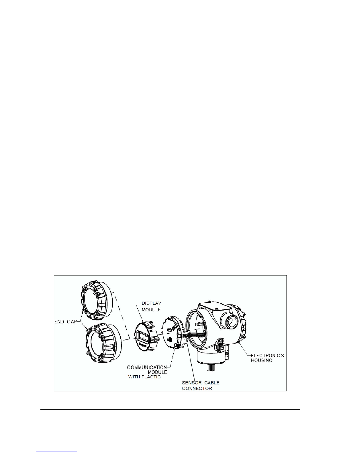
14. Select the proper Communication/External Configuration upgrade kit label from the label
strip provided and adhere to the inside of the Field Wiring compartment End Cap.
15. Apply Parker Super O-ring Lubricant or equivalent to the end cap o-ring before installing the
end cap. Reinstall the End Cap and tighten the end cap locking screw.
16. Install external upgrade label (i.e. DEVICE MODIFIED…..) provided on outside of housing
as shown in Figure 21.
17. Restore power if removed.
18. Check the settings of the Transmitter Setup and Display Setup parameters to make sure that
the transmitter is configured correctly for your application. See the User's Manual (ST 800
#34-ST-25-35, ST 700 #34-ST-25-44) for details on HART and DE transmitters. Refer to
manual #34-ST-25-39 for additional information about Fieldbus transmitters.
19. If applicable, verify External Button Configuration operation.
Ready to go.
5.5 Replacing the Meter Body
You can replace the complete meter body, including the process heads, or the meter body only on
certain Differential Pressure (DP), Gauge Pressure (GP), and Atmospheric Pressure (AP) Transmitters
by using the existing process head(s). Use the following procedure for meter body-only replacement.
1. Save or record device configuration data.
2. Turn off Transmitter power.
3. Remove the Transmitter from service, and move it to a clean area before disassembling it.
4. Refer to Figure 22. Loosen the End Cap Lock, and unscrew the End Cap from the electronics
side of the Transmitter housing.
Figure 22 – Disassembly for Meter Body Replacement
Page 72 ST 700 SmartLine Pressure Transmitters User’s Manual Revision 1.0
Page 51
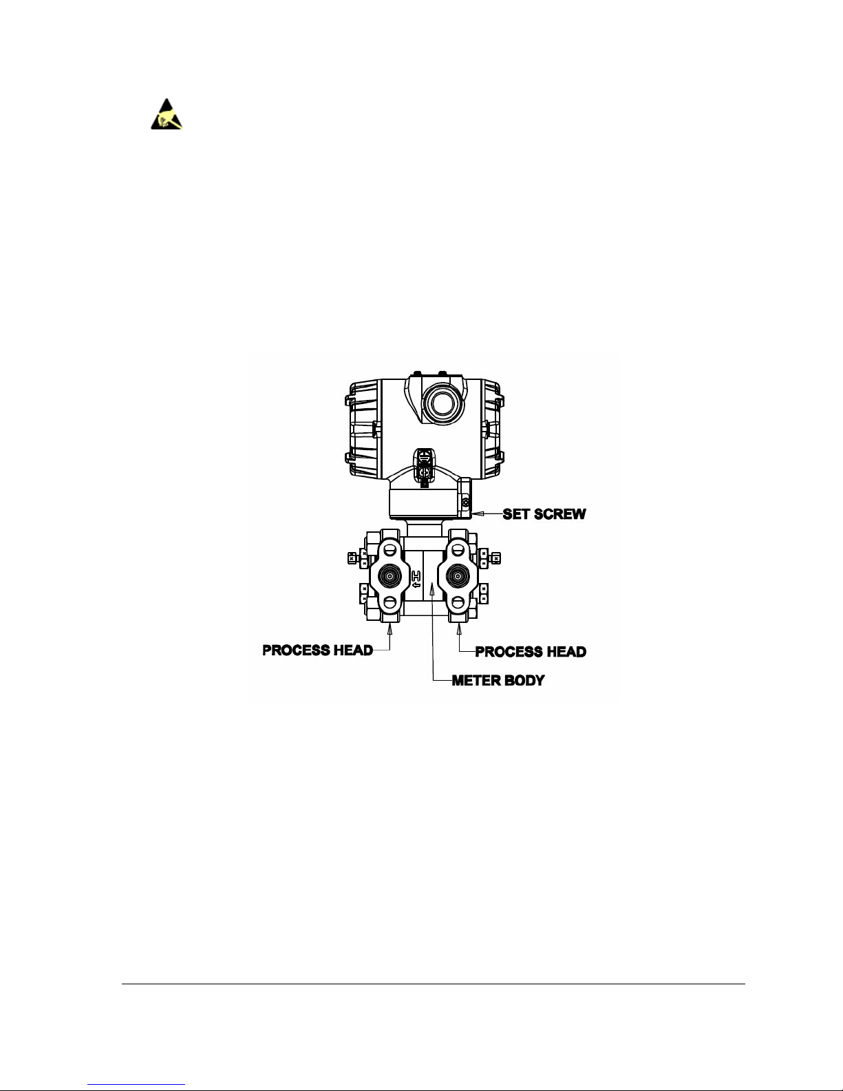
Please take appropriate steps to avoid ESD damage when handling the
Communication and Display Module assemblies
5. If a display is present, press the two snaps along the side, and remove it from the
communication module assembly.
Note: Do not discard or misplace the Display/Communication connector, it will be required
to reassemble the Display Module
6. Loosen the two retaining screws, and remove the Communications Module assembly, and
remove the Communication Module assembly from the electronics housing.
7. Disconnect the Sensor Cable from the Communications Board.
8. Refer to Figure 23. Use a 2 mm hex wrench to completely loosen the set screw on the outside
of the housing to permit rotating the meter body.
Figure 23 – Hardware Location to Remove the Meter Assembly
9. Carefully turn the complete meter body counterclockwise to unscrew it from the electronics
housing.
10. Remove the nuts from bolts that hold the process head(s) to the Meter Body.
11. Remove process heads and bolts.
12. Remove the gaskets or O-rings from the process heads.
13. Clean the interior of the process head(s) with a soft bristle brush and suitable solvent.
CAUTION
To prevent damage to the diaphragm in the Meter Body, use extreme care when
handling or placing the Meter Body on any surface. Carefully assemble gaskets or
O-rings to the meter body. If installing O-rings, lubricate with water or leave dry.
Revision 2.0 ST 700 Smart Pressure Transmitter User’s Manual Page 39
Page 52
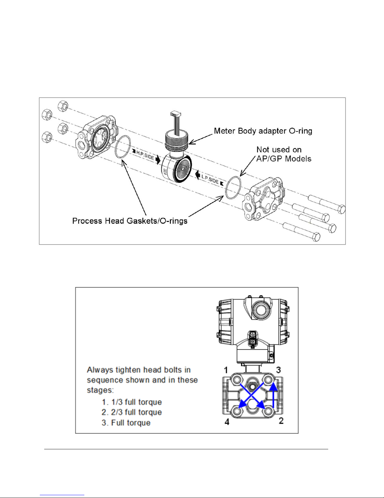
14. Coat threads on process head bolts with anti-seize compound such as “Neverseize” or
equivalent.
15. Refer to Figure 24. Apply Dow Corning #33 silicone grease to the meter body adapter O-ring
and carefully assemble the O-ring to the meter body. Assemble the process head(s) and bolts
to the new meter body. For now, make the bolts only finger-tight.
Figure 24 – Meter Body Reassembly
16. Use a torque wrench to gradually tighten nuts to torque rating in sequence shown in Figure 25.
Tighten head bolts in stages of 1/3 full torque, 2/3 full torque, and then full torque.
Figure 25 – Head Bolt Tightening Sequence
Page 72 ST 700 SmartLine Pressure Transmitters User’s Manual Revision 1.0
Page 53

17. Feed the ribbon cable on the new meter body through the neck of the housing.
CAUTION
To prevent damage to the ribbon cable, use care when assembling the Meter
Body to the electronics housing.
18. Screw the new meter body into the housing until the bottom of the Meter Body adapter is
flush with the neck of the electronics housing.
19. Tighten the outside set screw to be sure it is fully seated in the slot in the header.
20. Loosen the set screw ½- turn.
o
21. Rotate the housing to the desired position (Max. 180
screw.
22. Carefully align and connect the Sensor Ribbon Cable to connector “J4” at the bottom of the
Communication module board. When installing the Communication module in the next step,
be careful not to pinch the Sensor Ribbon Cable.
23. Carefully, insert the Communication module into the Electronics compartment. Ensure that
the Sensor Ribbon Cable is not pinched.
in either direction), and tighten the set
24. Tighten the two Communication module retaining screws.
25. If applicable, re-install the Display module as follows:
a) Orient the display as desired.
b) Install the Interface Connector in the Display module such that it will mate with
the socket for the display in the Communication module.
c) Carefully line up the display, and snap it into place. Verify that the two tabs on the
sides of the display latch.
Orient the Display for proper viewing through the end cap window.
You can rotate the meter mounting orientation in 90 o increments.
26. Connect the bracket to the Transmitter housing.
27. Recalibrate the Transmitter per Section 6 of this document.
28. Return the Transmitter to service, and turn ON power
29. Verify the Transmitter configuration data. Restore the saved database if necessary.
30. Lubricate the end-cap O-ring with Parker Super O-ring silicone lubricant or equivalent before
replacing the end caps.
Revision 2.0 ST 700 Smart Pressure Transmitter User’s Manual Page 41
Page 54

6 Calibration
6.1 Recommendations for Transmitter Calibration
The ST 700 Pressure Transmitter does not require periodic calibration to maintain accuracy.
Typically, calibration of a process-connected Transmitter will degrade, rather than augment the
capability of a smart Transmitter. For this reason, it is recommended that a Transmitter be removed
from service before calibration. Moreover, calibration will be accomplished in a controlled,
laboratory-type environment, using certified precision equipment.
6.2 Calibration Procedures
For a Transmitter operating in analog mode, you must calibrate its output signal measurement range
using any compatible hand-held communicator or a local display.
One calibration option is to use the Honeywell Smart Field Communicator (SFC). Refer to the Smart
Field Communicator Operating Guide, 34-ST-11-14 for calibration procedures.
Calibration information and procedures for a Transmitter operating in the HART/DE mode are
provided in the ST 700 Series HART/DE Option User’s Manual, document number 34-25-25-47,
Section on “Calibration.”
Page 72 ST 700 SmartLine Pressure Transmitters User’s Manual Revision 1.0
Page 55

7 Troubleshooting
7.1 Overview
Troubleshooting involves responding to error messages, primarily displayed by the MC Toolkit. Error
messages that may occur on the Transmitter’s local display are fairly self-explanatory and intuitive.
However, this section covers the diagnostic messages that indicate critical conditions. Other than the
critical conditions, additional detail is not provided. If you require assistance, contact your distributor
or Honeywell Technical Support. All other messages are covered by the MC Toolkit Users’ Manual.
7.2 Critical Diagnostics Screens
The Basic Display will display the message CRITCAL FAULT on the top line of the LCD and the
appropriate diagnostic text on the lower line.
A description of the diagnostic conditions is given in Table 14 along with suggested actions for
resolving the problem.
7.2.1 Fault Conditions and Recommended Corrective Actions
Table 14 – Fault Conditions and Recommended Corrective Actions.
Condtion Analysis
fault.
A critical failure has
been detected in the
Meter body
Electronics Module
Fault.
A critical failure has
been detected on
the HART, DE, or FF
Electronics Module.
Meter body Comm
fault.
Communications
between the Meter
body and the
Electronics Module
has failed.
Use a HART, DE, or FF
communicator to read the detailed
status information from the
transmitter. Refer to the appropriate
communicator manual to get more
information about the possible
causes of the failure.
Use a HART, DE, or FF
communicator to read the detailed
status information from the
transmitter. Refer to the appropriate
communicator manual for more
information about the possible
failure causes.
This could be the result of a failure
on either of these modules or the
cable that connects them.
Use a HART, DE, or FF
communicator to read the detailed
status information from the
transmitter. Refer to the
appropriate communicator manual
to get more information about the
possible causes of the failure.
Recommended Corrective
Action
Cycle power to the Transmitter. If
the problem continues to occur,
replace the Meter body.
Cycle power to the transmitter.
If the problem continues to occur
replace the Electronics Module.
Check the ribbon cable that
connects the Meter body to the
Electronics Module. Make sure
that the cable is securely plugged
into the Electronics Module. Make
sure that all pins are plugged into
the connector (i.e., make sure that
the connector is not offset in a way
that leaves some pins
unconnected).
Cycle power to the transmitter.
If the problem continues to occur
replace the Electronics Module. If
this does not fix the problem,
replace the Meter body.
Revision 2.0 ST 700 Smart Pressure Transmitter User’s Manual Page 43
Page 56

8 Parts List
8.1 Overview
Individually saleable parts for the various Transmitter models are listed in this section. Some parts are
illustrated for identification. Parts are identified and listed in the corresponding tables as follows:
• Individually saleable parts are indicated in each figure by key number callout.
• Parts that are supplied in kits are indicated in each illustration by key number callout with the
letter K prefix.
Table 15 is a summarized list of recommended spare parts.
Table 15 – Summary List of Recommended Spare Parts
Part Number Description
50049849-501
50049849-502
50049849-503
50049849-504
50049849-509
50049849-510
51452865-201
51452865-202
51452865-203
51462865-204
50075472-531
50075472-532
50075472-533
50075472-534
HART Electronics Module Without REED Sensor
PWA
HART Electronics Module With REED Sensor
PWA
DE Electronics Module Without REED Sensor
PWA
DE Electronics Module With REED Sensor PWA
FieldBus Electronics Module Without REED
Sensor PWA
FIeldBus Electronics Module With REED Sensor
PWA
Electronics Housing seals kit (includes O-rings)
Glass Filled PTFE
VITON
100% PTFE
GRAPHITE
HART/DE Terminal Block Assy Without Lightning
Protection
HART/DE Terminal Block Assy With Lightning
Protection
FieldBus Terminal Block Assy Without Lightning
Protection
FieldBus Terminal Block Assy With Lightning
Protection
Electronics Housing Assembly
Figure
No.
Figure
28
Figure
30
Figure
28
Key
No.
1-10
Units
5 1 1-2 2-4
K1 1 1-2 2-4
3 1 1-2 2-4
10-100
Units
100-
1000
Units
Page 72 ST 700 SmartLine Pressure Transmitters User’s Manual Revision 1.0
Page 57
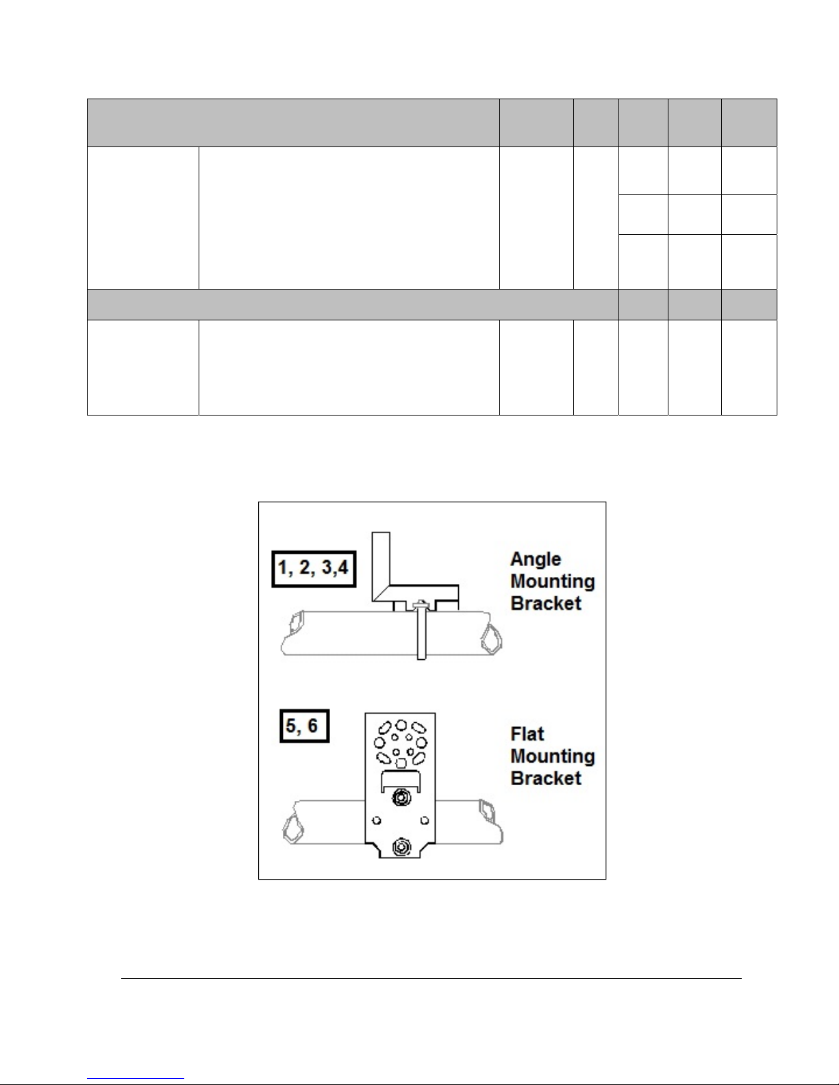
51452868-501
51452868-502
51452868-507
Specify
complete
model
number from
nameplate
Process head gasket kit
Gasket only, Process Head (12 PTFE packs)
Gasket only, Process Head (6 Viton Head
O’Rings)
Gasket only, Process Head Graphite Gasket
(replacement only for existing graphite gasket)
Meter Body
DP Models
GP/AP HEAD Models
LGP/LAP Models
Flush Mount Models
Flange Mount Models
Figure
No.
Figure 30 Ka
Figure 29
Key
No.
1-10
Units
10100
Units
12
12-24
6 6-12 12-24
6 6-12 12-24
1 1-2 2-4
1001000
Units
24-48
Revision 2.0 ST 700 Smart Pressure Transmitter User’s Manual Page 45
Figure 26 – Angle and Flat Bracket Parts
Page 58

Key
No.
Table 16 – Angle and Flat Bracket Parts
(Refer to Figure 26)
Part Number Description
Quantity
Per Unit
1 30752770-103
2 30752770-104
3 30752770-303
4 30752770-304
5 51196557-005
6 51196557-006
7 30752770-403
8 30752770-404
9 51196557-008
10 51196557-009
SS 304 Angle Bracket Mounting kit for all models except Inline and Flush mount transmitters
SS 304 Angle Bracket Mounting kit for all In-Line and Flush
mount transmitters
Marine Approved Angle Bracket for all models except In-line
and Flush mount transmitters
Marine Approved Angle Bracket for all In-line and Flush
mount transmitters
SS 304 Flat Bracket Mounting kit for all models except In-line
and Flush mount transmitters
SS 304 Flat Bracket Mounting kit for all In-line transmitters
and Flush mount transmitters
SS 316 Flat Bracket Mounting kit for all In-line transmitters
except In-Line and Flush mount transmitters
SS 316 Flat Bracket Mounting kit for all In-Line and Flush
mount transmitters
SS 316 Flat Bracket Mounting kit for all In-line transmitters
except In-Line and Flush mount transmitters
SS 316 Flat Bracket Mounting kit for all In-Line and Flush
mount transmitters
1
1
1
1
1
1
1
1
1
1
Page 72 ST 700 SmartLine Pressure Transmitters User’s Manual Revision 1.0
Page 59
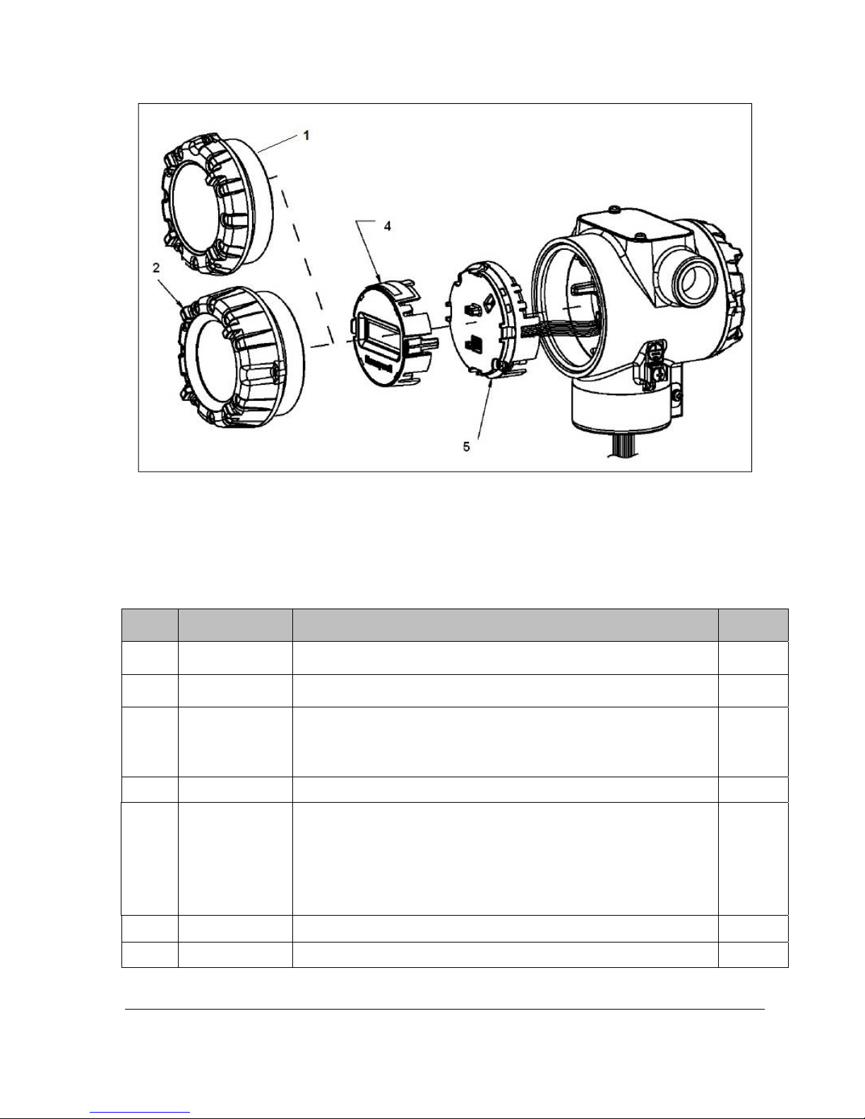
Figure 27 – Electronic Housing, Display End
Table 17 – Transmitter Major Assemblies
(Refer to Figure 26, Figure 28 and Figure 29)
Key
No.
1
2
3
4 50049911-501 Basic Display 1
5
Part Number Description
50049858-501
50049858-521
50049832-501
50049832-521
50075472-531
50075472-532
50075472-533
50075472-534
50049849-501
50049849-502
50049849-503
50049849-504
50049849-509
50049849-510
End Cap (Aluminum)
End Cap (Stainless Steel)
End Cap, Display (Aluminum)
End Cap, Display (Stainless Steel)
Terminal Assy HART/DE without Lightning protection
Terminal Assy HART/DE with Lightning protection
Terminal Assy FF/PB without Lightning protection
Terminal Assy FF/PB with Lightning protection
HART Electronics Module Assembly (PWA) without Reed sensor
HART Electronics Module Assembly (PWA) with Reed sensor
DE Electronics Module Assembly (PWA) without Reed sensor
DE Electronics Module Assembly (PWA) with Reed sensor
FF Electronics Module Assembly (PWA) without Reed sensor
FF Electronics Module Assembly (PWA) with Reed sensor
Quantity
Per Unit
1
1
1
1
6 50049915-501 External Zero, Span & Config Buttons 1
K1 30757503-005 Electronics housing seals kit (includes O-rings) 2
Revision 2.0 ST 700 Smart Pressure Transmitter User’s Manual Page 47
Page 60
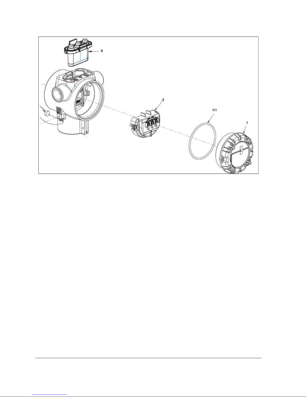
Figure 28 – Electronic Housing, Terminal Block End
Page 72 ST 700 SmartLine Pressure Transmitters User’s Manual Revision 1.0
Page 61
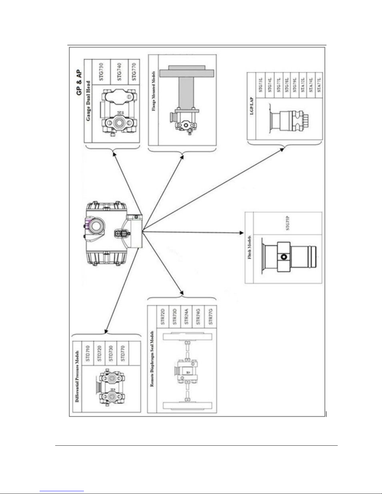
Revision 2.0 ST 700 Smart Pressure Transmitter User’s Manual Page 49
Figure 29 – Transmitter Major Assemblies
Page 62

Table 18 – ST 700 Models STD710, 720, 730, 770 & STG774 (Ref. Figure 29)
Key
No.
30753785-001
Part Number Description Qty/Unit
Vent and Plug Kits
Drain and Plug Kit, stainless steel
30753787-001
30753786-001
Drain and Plug Kit, Monel
Drain and Plug Kit, Hastelloy C
Each Drain and Plug Kit includes:
K1 Pipe Plug 4
K2 Vent Plug 2
K3 Vent Bushing 2
Meter Body Gasket Kits
51452865-201
51452865-202
51452865-203
51452865-204
Gasket, Process Head
K6
Each Meter Body Gasket Kit includes:
Glass Filled PTFE
VITON
100% PTFE
GRAPHITE
6
Ka Gasket, Flange Adapter 6
O-Ring, Meter Body to Electronics Housing
K7
K6
K6
K6
51452868-501
51452868-502
51452868-507
K7 Process Head Gasket Kits
Gasket only, Process Head (12 PTFE Gaskets/pack)
Gasket only, Process Head (6 Viton Head O-Rings)
Gasket only, Process Head Graphite Gasket (use only as
3
12
6
6
replacement of existing graphite gasket)
Ka
Ka
Ka
51452868-504
51452868-505
51452868-508
Flange Adapter Gasket Kits
Gasket only, Flange Adapter, 6 PTFE Adapter Gaskets
Gasket only, Flange Adapter, 6 VITON Adapter O-Rings
Gasket only, Flange Adapter Graphite Gasket (use only as
6
6
6
replacement of existing graphite gasket)
51452867-110
51452867-210
51452867-310
51452867-410
51452867-150
51452867-350
51452867-130
51452867-330
½-Inch NPT Flange Adapter Kits
Flange Adapter Kit, with
SS Flange Adapters and with carbon steel bolts
SS Flange Adapters and with A286 SS (NACE) bolts
SS Flange Adapters and with 316 SS (non-NACE) bolts
SS Flange Adapters and with B7M alloy steel bolts
Monel Flange Adapters and with carbon steel bolts
Monel Flange Adapters and with 316 SS (non-NACE) bolts
Hastelloy C Flange Adapters and with carbon steel bolts
Hastelloy C Flange Adapters and with 316 SS (non-NACE)
:
bolts
Ka Gasket, Flange Adapter
Kb 1/2-inch NPT Flange Adapter
Kc Bolt, hex head, 7/16-20 UNF, 1.50 inches long
Each 1/2-inch NPT Flange Adapter Kit includes:
2
2
4
Page 72 ST 700 SmartLine Pressure Transmitters User’s Manual Revision 1.0
Page 63
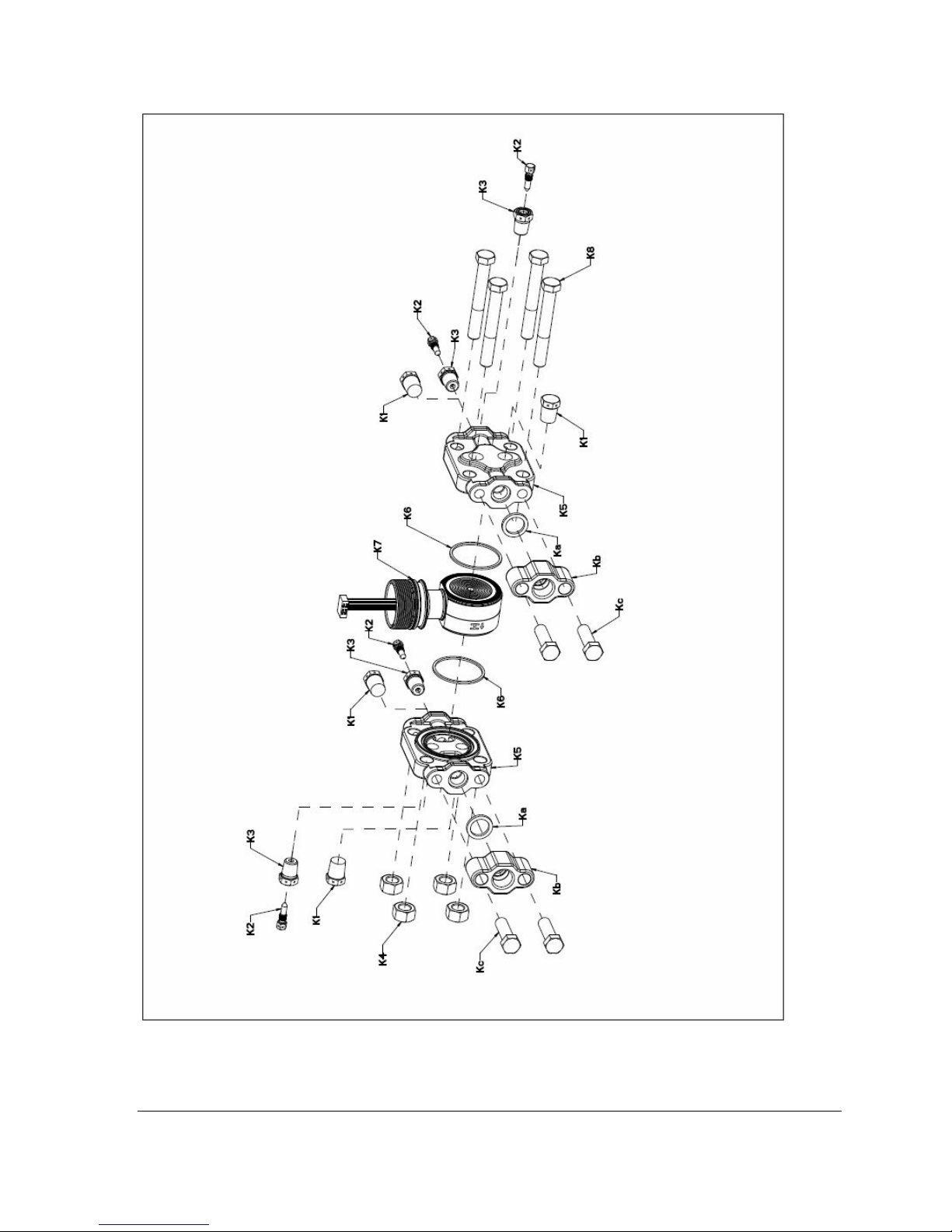
Figure 30 - ST 700 Models STD710, 720, 730, & 770
Revision 2.0 ST 700 Smart Pressure Transmitter User’s Manual Page 51
(Refer to
Table 18)
Page 64

Table 19 – Parts for STG730, 740, 770 and STA722, 740 Transmitter Body
(Ref. Figure 32)
Key
No.
51452864-010
51452864-110
K1 Pipe Plug (See notes 1 & 2) 1
K2 Vent Plug (See note 1) 1
K3 Vent Bushing (See note 1.) 1
K5 Process Head 1
K6 Gasket (PTFE), Process Head 1
Ka Gasket (PTFE), Flange Adapter 1
Note 1: This item is made of the same material as the Process Heads, except for Kits with
K9
K9
Part Number Description Qty/Unit
Process Head Assembly Kits with PTFE Gaskets
51452864-012
51452864-020
51452864-022
51452864-030
51452864-032
51452864-040
51452864-042
51452864-050
51452864-052
Carbon steel head (zinc plated) without side vent/drain
Carbon steel head (zinc plated) with side vent/drain
Stainless steel head without side vent/drain
Stainless steel head with side vent/drain
Hastelloy C head without side vent/drain
Hastelloy C head with side vent/drain
Monel head without side vent/drain
Monel head with side vent/drain
Carbon steel head (nickel plated) without side vent/drain
Carbon steel head (nickel plated) with side vent/drain
Process Head Assembly Kits with PTFE Gaskets
51452864-112
51452864-120
51452864-122
51452864-130
51452864-132
51452864-140
51452864-142
51452864-150
51452864-152
Carbon steel head (zinc plated) without side vent/drain
Carbon steel head (zinc plated) with side vent/drain
Stainless steel head without side vent/drain
Stainless steel head with side vent/drain
Hastelloy C head without side vent/drain
Hastelloy C head with side vent/drain
Monel head without side vent/drain
Monel head with side vent/drain
Carbon steel head (nickel plated) without side vent/drain
Carbon steel head (nickel plated) with side vent/drain
Each process head assembly kit includes:
Notes
carbon steel Process Heads, which include stainless steel Pipe Plug, Vent Plug, and Vent
Bushing.
Note 2: The Kit for Process Heads without side vent/drain does not include Pipe Plugs (K1).
Reference Head
51452951-201
51452951-101
Carbon Steel Blind Reference Head
316 SS Blind Reference Head
1
1
Page 72 ST 700 SmartLine Pressure Transmitters User’s Manual Revision 1.0
Page 65

Key
No.
Figure 31 – STG730, 740, 770, and STA722, 740 Transmitter Body (Ref.)
Table 20 - Inline Gauge and Inline Atmospheric Meter Body Parts
Part Number Description Qty/Unit
Specify complete
ST Series replacement meter body (LAP/LGP model)
model number from
nameplate
1
Revision 2.0 ST 700 Smart Pressure Transmitter User’s Manual Page 53
Page 66

Figure 32 – Inline Gauge and Inline Atmospheric Meter Body Bodies
Table 21 – Flange-Mounted Meter Body Parts (Ref Figure 32)
Key
No.
1 Specify
K1
K2
K3
K4
K1
K2
K3
K5 30757503-001
Part Number Description Qty/Unit
complete model
number from
nameplate
30749372-005
30749372-001
30754419-006
30754419-008
30754419-022
30754419-024
30754419-007
30754419-023
ST Series 700 replacement meter body
O-ring seal
O-ring seal
Optional Flange Adapter - Not Shown
Flange adapter kit (st. steel flange adapter with carbon steel
bolts)
Flange adapter kit (Monel flange adapter with carbon steel
bolts)
Flange adapter kit (st. steel flange adapter with 316 st. steel
bolts)
Flange adapter kit (Monel with 316 st. steel bolts)
Bolt, hex head, 7/16-20 UNF, 1.375 inches lg.
Flange adapter
Gasket
Filter screen
Flange adapter kit (Hastelloy C flange adapter with carbon
steel bolts)
Flange adapter kit (Hastelloy C flange adapter with 316 st.
steel bolts)
Bolt, hex head, 7/16-20 UNF, 1.375 inches lg.
Flange adapter
Gasket
Housing seal kit
1
1
1
2
1
1
1
2
1
1
1
Page 72 ST 700 SmartLine Pressure Transmitters User’s Manual Revision 1.0
Page 67
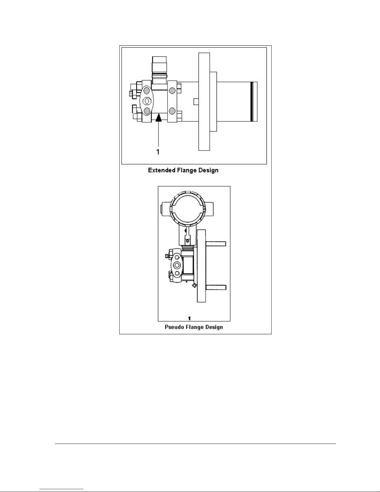
Revision 2.0 ST 700 Smart Pressure Transmitter User’s Manual Page 55
Figure 33 – Flange Mounted Meter Body
Page 68
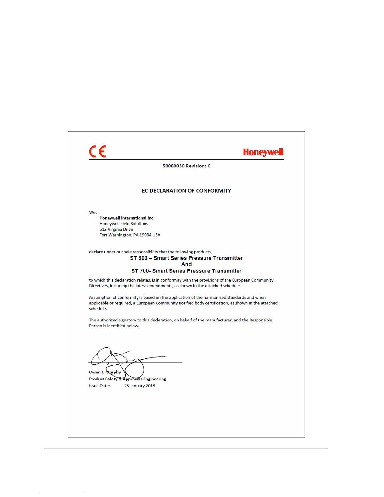
Appendix A. PRODUCT CERTIFICATIONS
A1. Safety Instrumented Systems (SIS) Installations
For Safety Certified Installations, please refer to SmartLine Safety Manual 34-ST-25-37 for
installation procedure and system requirements.
A2. European Directive Information (CE Mark)
Page 72 ST 700 SmartLine Pressure Transmitters User’s Manual Revision 1.0
Page 69
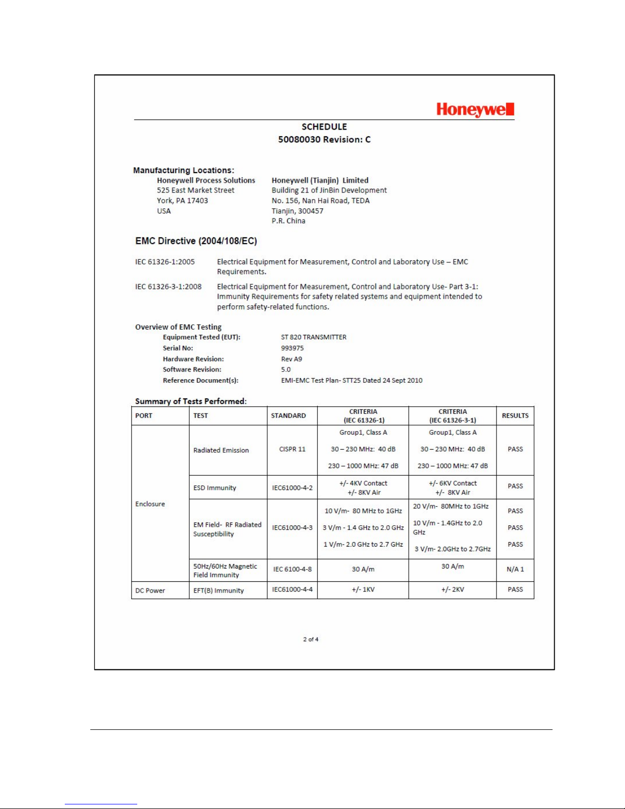
Revision 2.0 ST 700 Smart Pressure Transmitter User’s Manual Page 57
Page 70
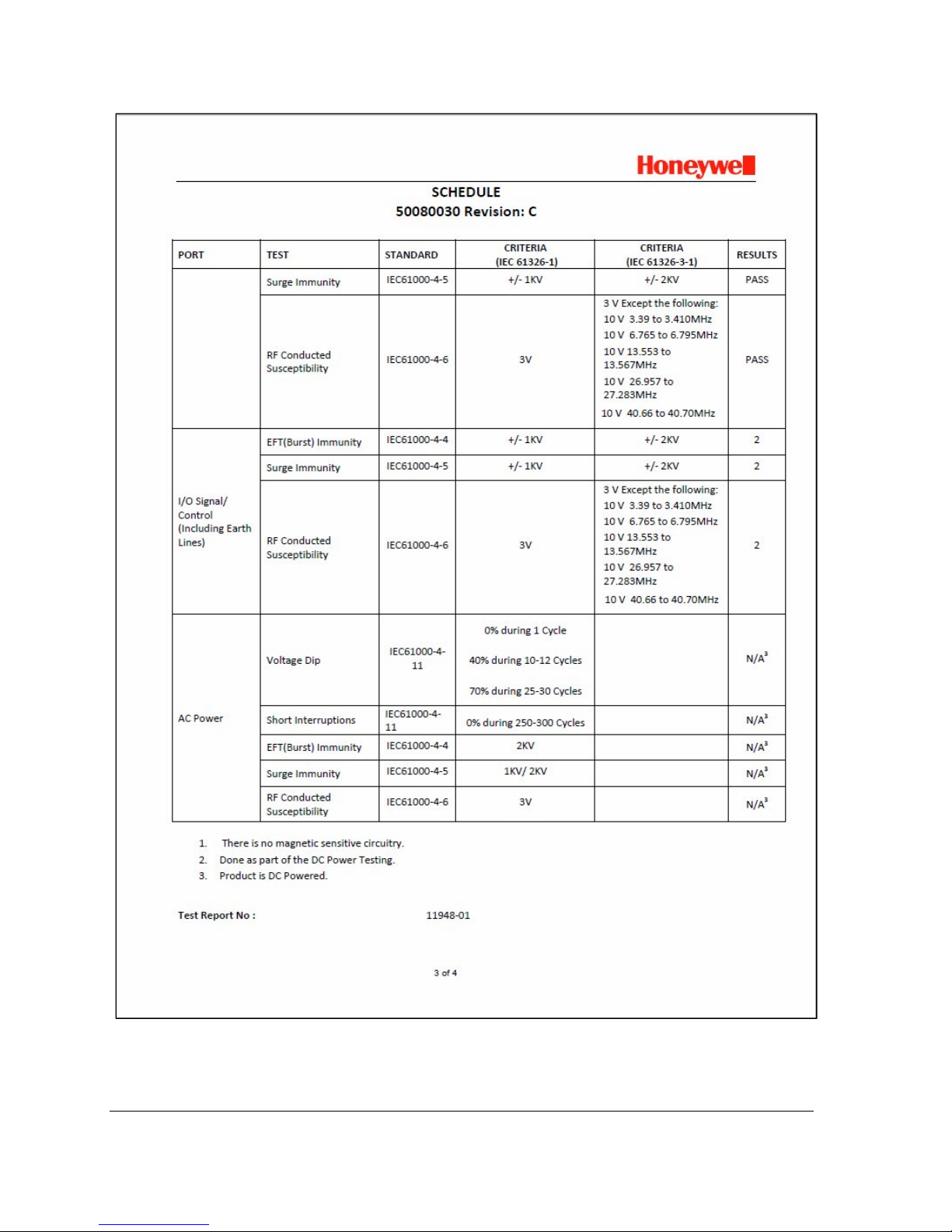
Page 72 ST 700 SmartLine Pressure Transmitters User’s Manual Revision 1.0
Page 71
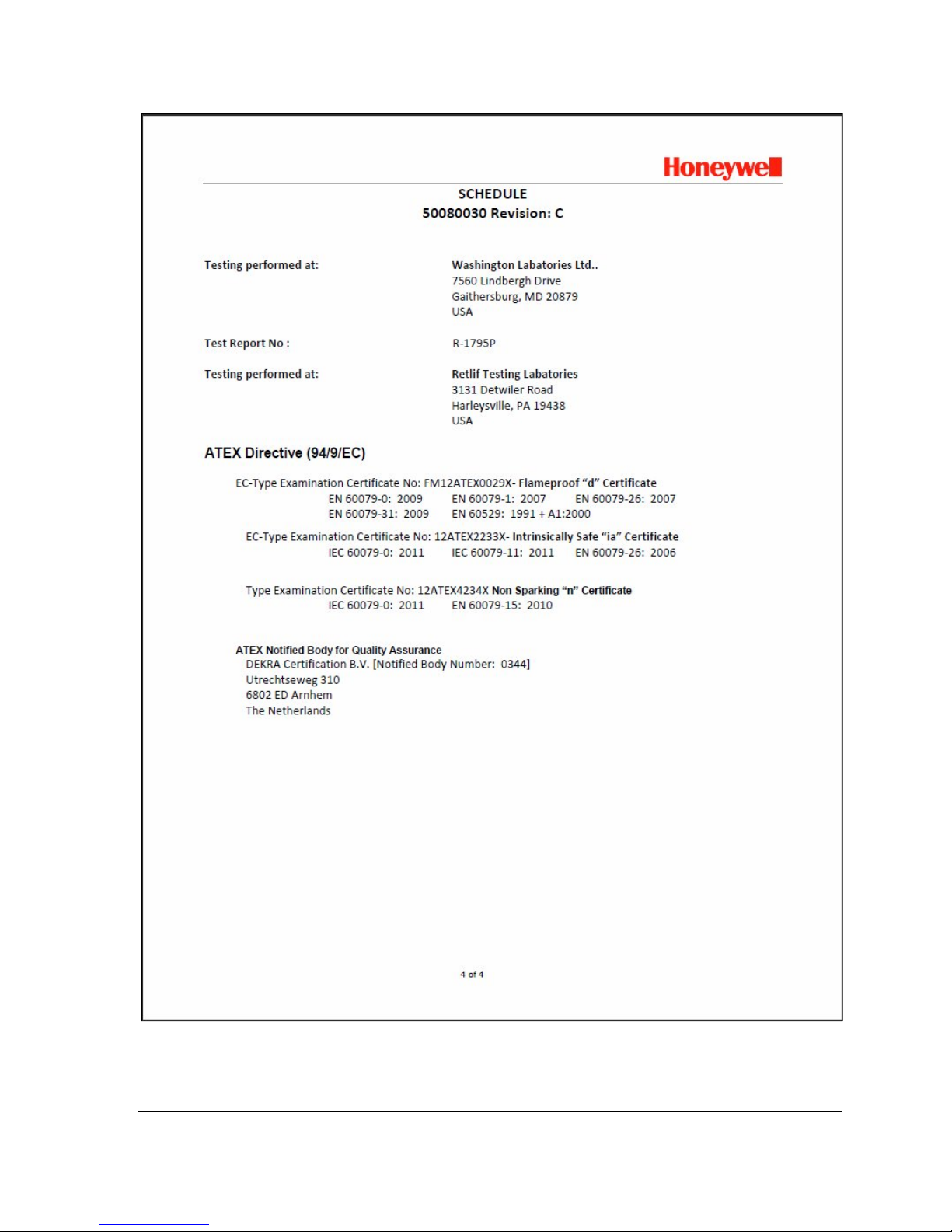
Revision 2.0 ST 700 Smart Pressure Transmitter User’s Manual Page 59
Page 72

A3. Hazardous Locations Certifications
AGENCY TYPE OF PROTECTION
Explosion proof:
Class I, Division 1, Groups A, B, C, D;
Dust Ignition Proof:
Class II, III, Division 1, Groups E, F, G;
T4
Class 1, Zone 1/2, AEx d IIC T4
Class 2, Zone 21, AEx tb IIIC T 95
IP 66
Standards: FM 3600:2011; ANSI/ ISA 60079-0: 2009
FM 3615:2006; ANSI/ ISA 60079-1 : 2009
FM 3616 : 2011 ; ANSI/ ISA 60079-31 : 2009
FM 3810 : 2005 ; ANSI/ ISA 60079-26 : 2008
NEMA 250 : 2003 ; ANSI/ IEC 60529 : 2004
Intrinsically Safe:
Class I, II, III, Division 1, Groups A, B,
FM
Approvals
USA
C, D, E, F, G; T4
TM
Class I Zone 0 AEx ia IIC T4
Ex ia IIC T4
Standards: FM 3600:2011; ANSI/ ISA 60079-0: 2009
FM 3610:2010; ANSI/ ISA 60079-11 : 2011
FM 3810 : 2005 ; ANSI/ ISA 60079-26 : 2008
NEMA 250 : 2003 ; ANSI/ IEC 60529 : 2004
Class I, Division 2, Groups A, B, C, D;
T4
Class I Zone 2 AEx nA IIC T4
Ex nA IIC T4
COMM.
OPTION
4-20 mA /
DE/ HART
o
C
4-20 mA /
DE/ HART
4-20 mA /
DE/ HART
FIELD
PARAMETERS
AMBIENT
TEMP (Ta)
Note 1 -50ºC to 85ºC
Note 2 -50 ºC to 70ºC
Note 1 -50 ºC to 85ºC
Standards: FM 3600:2011; ANSI/ ISA 60079-0: 2009
FM 3611:2004; ANSI/ ISA 60079-15 : 2009 ; FM 3810 : 2005 ;
NEMA 250 : 2003 ; ANSI/ IEC 60529 : 2004
CSA
US and
Canada
Enclosure: Type 4X/ IP66/ IP67
Intrinsically Safe:
Class I, II, III, Division 1, Groups A, B,
C, D, E, F, G; T4
Class I Zone 0 AEx ia IIC T4
Ex ia IIC T4
Class I, Division 2, Groups A, B, C, D;
T4
Class I Zone 2 AEx nA IIC T4
Ex nA IIC T4
Enclosure: Type 4X/ IP66/ IP67
Standards: ANSI/ ISA 60079-0: 2009 ; CAN/ CSA-C22.2 No. 0-M91:2006; CAN/ CSA-
E60079-0:2002 ; ANSI/ UL 913 : 2010 ; ANSI/ ISA 60079-11 : 2009 ; CAN/ CSA-C22.2
No.157-92: 1992; CAN/CSA-E 60079-11: 2002; ANSI/ ISA 60079-26 : 2008
All All All
4-20 mA /
DE/ HART
4-20 mA /
DE/ HART
All All All
Note 2 -50 ºC to 70ºC
Note 1 -50 ºC to 85ºC
Page 72 ST 700 SmartLine Pressure Transmitters User’s Manual Revision 1.0
Page 73

AGENCY TYPE OF PROTECTION
ANSI/ ISA 12.12.01 : 2007 ; ANSI/ ISA 60079-15 : 2009 ;
C22.2 No. 213-M1987; CAN/CSA-E60079-15: 2002
ANSI/ UL 50 : 2007 ; ANSI/ IEC 60529 : 2004
Flameproof:
II 1/2 G Ex d IIC T4
II 2 D Ex tb IIIC T 85
o
Enclosure: IP66/ IP67 All All All
ATEX- FM
Standards: EN 60079-0: 2011
EN 60079-1 : 2007
EN 60079-31 : 2009
EN 60079-26 : 2007
EN 60529 : 2000 + A1
Intrinsically Safe:
II 1 G Ex ia IIC T4
Nonincendive:
II 3 G Ex nA IIC T4
ATEX- SIRA
IECEx- FM
IECEx- CSA
Enclosure: IP66/ IP67
Standards: EN 60079-0: 2011
EN 60079-11 : 2011
EN 60079-26 : 2006
EN 60079-15 : 2007
IEC 60529 : 2009 with Corr 3
Flameproof :
Ga/Gb Ex d IIC T4
Ex tb IIIC T 85
Enclosure: IP66/ IP67
Standards: IEC 60079-0: 2011
IEC 60079-1 : 2007
IEC 60079-31 : 2008
IEC 60079-26 : 2006
Intrinsically Safe:
Ex ia IIC T4
Ex ta IIIC T 85
Nonincendive:
Ex nA IIC T4
Enclosure: IP66/ IP67
Standards: IEC 60079-0: 2011
IEC 60079-11 : 2011
IEC 60079-26 : 2006
IEC 60079-15 : 2011
IEC 60529 : 2009 with Corr 3
o
C IP 66
IEC 60529 : 2009 with Corr 3
o
C IP 66
C IP 66
COMM.
OPTION
FIELD
PARAMETERS
AMBIENT
TEMP (Ta)
All Note 1 -50 ºC to 85ºC
4-20 mA /
DE/ HART/
FF
4-20 mA /
DE/ HART/
All All All
All Note 1 -50 ºC to 85ºC
All All All
4-20 mA /
DE/ HART/
FF
4-20 mA /
DE/ HART/
All All All
Note 2 -50 ºC to 70ºC
Note 1 -50 ºC to 85ºC
Note 2 -50 ºC to 70ºC
Note 1 -50 ºC to 85ºC
Revision 2.0 ST 700 Smart Pressure Transmitter User’s Manual Page 61
Page 74

Notes
Operating Parameters:
(Loop Terminal)
Voltage= 11 to 42 V Current= 4-20 mA Normal (3.8 – 23 mA Faults)
Intrinsically Safe Entity Parameters
Analog/ DE/ HART Entity Values:
Vmax= Ui = 30V Imax= Ii= 105mA Ci = 3.8nF Li =820 uH Pi = 0.9 W
For further details see Control Drawing on the next page.
A4. Marking ATEX Directive
General:
The following information is provided as part of the labeling of the transmitter:
• Name and Address of the manufacturer
• Notified Body identification: DEKRA Quality B.V., Arnhem, the Netherlands
• For complete model number, see the Model Selection Guide for the particular model of
pressure transmitter.
• The serial number of the transmitter is located on the Meter Body data-plate. The first two
digits of the serial number identify the year (02) and the second two digits identify the
week of the year (23); for example, 0223xxxxxxxx indicates that the product was
manufactured in 2002, in the 23rd week.
Apparatus Marked with Multiple Types of Protection
The user must determine the type of protection required for installation the equipment. The
user shall then check the box [] adjacent to the type of protection used on the equipment
certification nameplate. Once a type of protection has been checked on the nameplate, the
equipment shall not then be reinstalled using any of the other certification types.
WARNINGS and Cautions:
Intrinsically Safe and Non-Incendive Equipment:
WARNING: SUBSTITUTION OF COMPONENTS MAY IMPAIR SUITABILITY FOR
USE IN HAZARDOUS LOCATIONS.
Explosion-Proof/ Flameproof:
WARNING: DO NOT OPEN WHEN AN EXPLOSIVE ATMOSPHERE MAY BE
PRESENT
Non-Incendive Equipment:
WARNING: DO NOT OPEN WHEN AN EXPLOSIVE ATMOSPHERE MAYBE
PRESENT
All Protective Measures:
WARNING: FOR CONNECTION IN AMBIENTS ABOVE 60oC USE WIRE RATED
105oC
Page 72 ST 700 SmartLine Pressure Transmitters User’s Manual Revision 1.0
Page 75

A.5 Conditions of Use” for Ex Equipment”, Hazardous
Location Equipment or “Schedule of Limitations”:
Consult the manufacturer for dimensional information on the flameproof joints for repair.
Painted surface of the ST 700 may store electrostatic charge and become a source of ignition
in applications with a low relative humidity less than approximately30% relative humidity
where the painted surface is relatively free of surface contamination such as dirt, dust or oil.
Cleaning of the painted surface should only be done with a damp cloth.
Flame-proof Installations: The Transmitter can installed in the boundary wall between an
area of EPL Ga/ Class I Zone 0/ Category 1 and the less hazardous area, EPL Gb/ Class I
Zone 1/ Category 2. In this configuration, the process connection is installed in EPL Ga/
Class I Zone 0/ Category 1, while the transmitter housing is located in EPL Gb/ Class I Zone
1/ Category 2.
Intrinsically Safe: Must be installed per drawing 50049892
Division 2: This equipment is suitable for use in a Class I, Division 2, Groups A, B, C, D; T4
or Non-Hazardous Locations Only.
Revision 2.0 ST 700 Smart Pressure Transmitter User’s Manual Page 63
Page 76
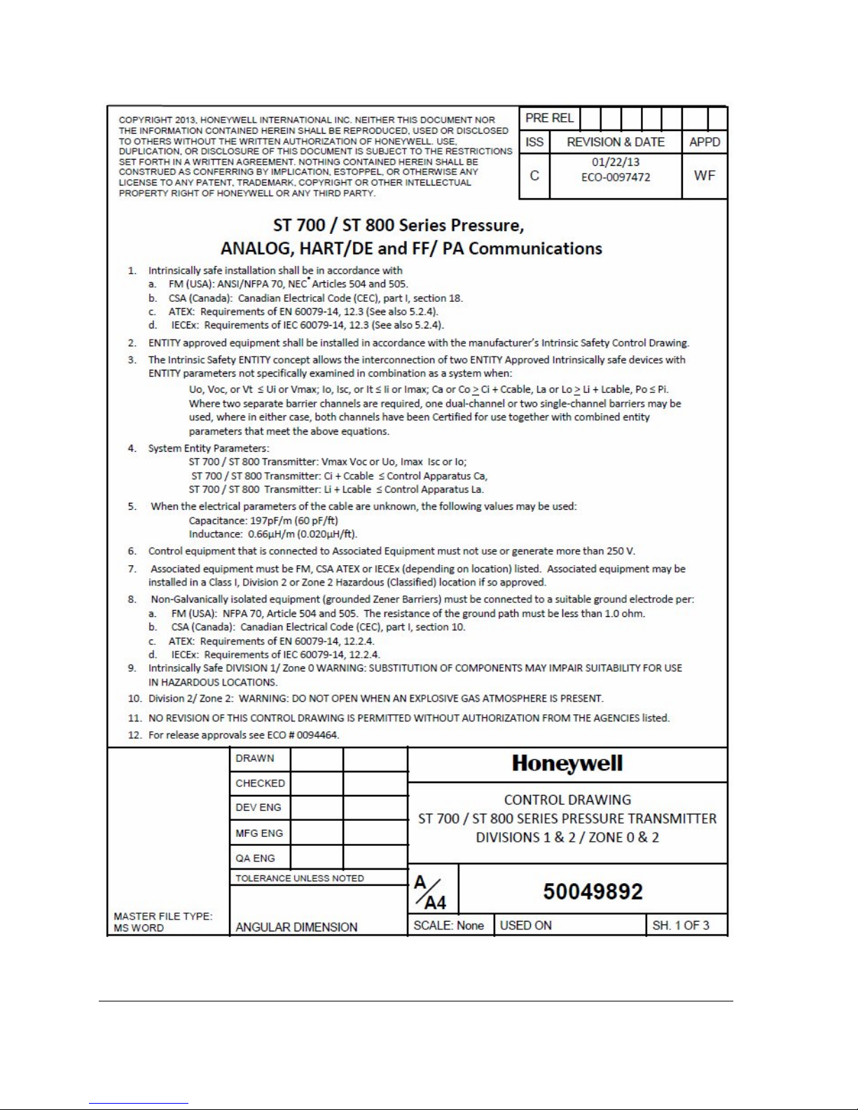
Page 72 ST 700 SmartLine Pressure Transmitters User’s Manual Revision 1.0
Page 77
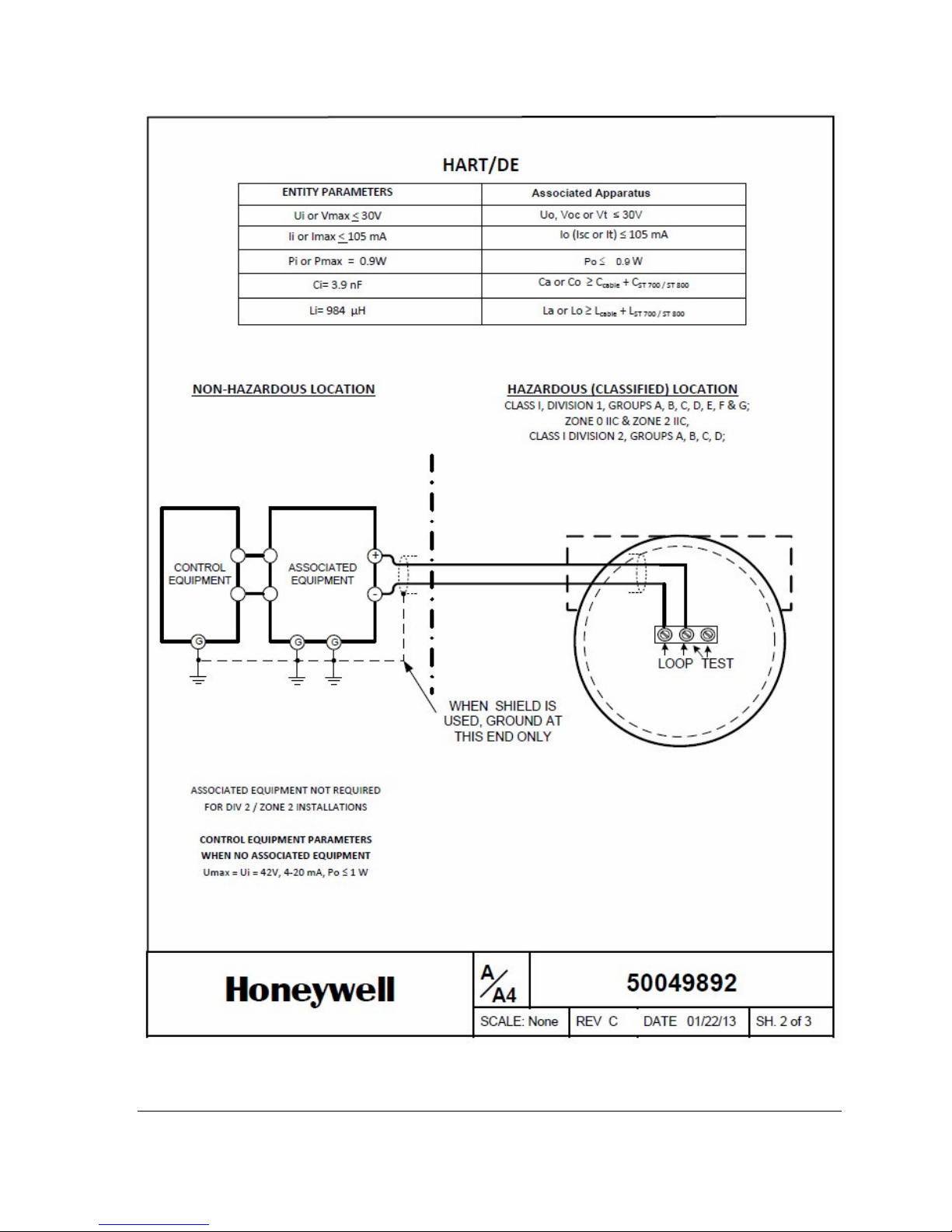
Revision 2.0 ST 700 Smart Pressure Transmitter User’s Manual Page 65
Page 78
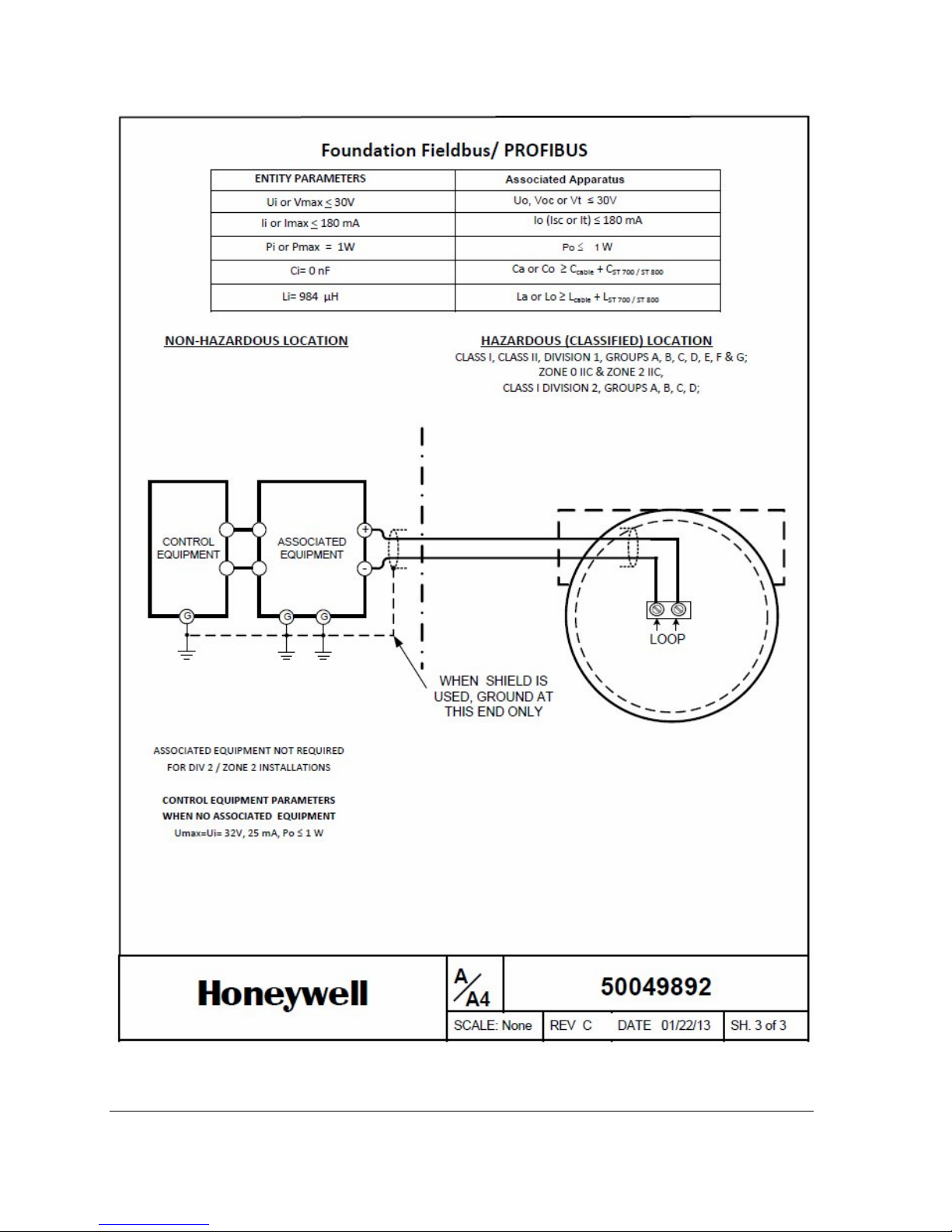
Page 72 ST 700 SmartLine Pressure Transmitters User’s Manual Revision 1.0
Page 79

Glossary
AP Absolute Pressure
AWG American Wire Gauge
DE Digital Enhanced Communications Mode
DP Differential Pressure
d1 Inside diameter of pipe
d2 Orifice plate bore diameter at flowing temperature
do Inside diameter of orifice
EMI Electromagnetic Interference
FTA Field Termination Assembly
GP Gauge Pressure
HP High Pressure (also, High Pressure side of a Differential Pressure Transmitter)
Hz Hertz
inH
2O Inches of Water
LGP In-Line Gauge Pressure
LP Low Pressure (also, Low Pressure side of a Differential Pressure Transmitter)
LRL Lower Range Limit
LRV Lower Range Value
mAdc Milliamperes Direct Current
mmHg Millimeters of Mercury
mV Millivolts
Nm Newton
.
meters
NPT National Pipe Thread
NVM Non-Volatile Memory
Pa Measured static pressure in PV4 algorithm
Pc Absolute critical pressure of the gas
Pd Static pressure at downstream point
Pdp Measured differential pressure in Pascals in PV4 algorithm
Pf Absolute pressure of flowing gas
Pr Reduced pressure
Pu Static pressure at upstream point
PM Process Manger
PSI Pounds per Square Inch
PSIA Pounds per Square Inch Absolute
PV Process Variable
PWA Printed Wiring Assembly
RFI Radio Frequency Interference
RTD Resistance Temperature Detector
SFC Smart Field Communicator
STIM Pressure Transmitter Interface Module
STIMV IOP Pressure Transmitter Interface Multivariable Input/Output Processor
T/C Thermocouple
URL Upper Range Limit
URV Upper Range Value
US Universal Station
Vac Volts Alternating Current
Vdc Volts Direct Current
Revision 2.0 ST 700 Smart Pressure Transmitter User’s Manual Page 67
Page 80

Index
A
About This Manual ......................................................... iv
Accuracy.......................................................................... 5
Application Design .......................................................... 5
B
Basic Display Menus ..................................................... 23
Bracket Mounting ........................................................... 9
C
Changing the Default Failsafe Direction ........................ 28
DE and Analog Differences ....................................... 28
Failsafe Operation .................................................... 29
Copyrights, Notices and Trademarks ............................. iii
D
Diagnostic Messages ....................................................... 5
Display Installation Precautions ...................................... 7
Display Options ............................................................... 4
F
Features and Options ...................................................... 1
Functional Characteristics .......................................... 2
Physical Characteristics .............................................. 1
Flange Mounting ........................................................... 12
G
M
Maintenance ................................................................ 33
Inspecting and Cleaning Barrier Diaphragms .......... 33
Preventive Maintenance Practices and Schedules .. 33
Replacing the Communication Module ................... 36
Replacing the Meter Body ....................................... 38
Monitoring the Basic Displays ...................................... 32
Mounting Dimensions .................................................... 8
Mounting ST 700 SmartLine Pressure Transmitters
Absolute or Differential ........................................... 11
Bracket Mounting Procedure .................................... 9
Flange Mounting ..................................................... 12
Levelling a Transmitter ............................................ 11
Remote Diaphragm Seal .......................................... 13
Mounting ST 700 SmartLine Pressure Transmitters ....... 8
Mounting Dimentsions .............................................. 8
Summary ................................................................... 8
Mounting Transmitters with Small Absolute or
Differential Pressure Spans ..................................... 11
N
Name Plate ..................................................................... 3
O
Operation ..................................................................... 22
Changing the Default Failsafe Direction .................. 28
Three Button Operation with no Display Installed .. 28
Three-Button Operation .......................................... 22
Optional 3-Button Assembly .......................................... 4
Glossary ........................................................................ 67
H
Honeywell MC Toolkit ..................................................... 7
I
Installation and Startup .................................................. 7
Display Installation Precautions ................................. 7
Mounting ST 700 SmartLine Pressure Transmitters ... 7
Site evaluation ........................................................... 7
Installation Site Evaluation
Site Evaluation ........................................................... 7
Introduction .................................................................... 1
Parts List ....................................................................... 44
Patent Notice ................................................................. v
Piping the ST 700 Transmitter
Piping Arrangements ............................................... 14
Transmitter location ................................................ 15
Piping the ST 700 Transmitter ...................................... 14
Pressure, Analog, HART and DE Communication ......... 56
References ..................................................................... iv
Release Information ....................................................... iv
Remote Diaphragm Seal Mounting .............................. 13
P
R
Page 72 ST 700 SmartLine Pressure Transmitters User’s Manual Revision 1.0
Page 81

S
Safety
Safety Integrity Level .................................................. 6
Safety Certification ......................................................... 3
Startup .......................................................................... 19
Constant Current Source Mode Procedure .............. 20
Output Check Procedures ........................................ 20
Support and Contact Information ................................... v
Symbol Descriptions and Definitions ............................. vi
T
Telephone and Email Contacts........................................ v
Three Button Operation with no Display Installed ........ 28
Span Adjustments .................................................... 28
Zero Adjustments ..................................................... 28
Three-Button Operation ............................................... 22
Data Entry ................................................................ 27
Transmitter Adjustments ................................................ 3
Troubleshooting ............................................................ 43
Critical Diagnostics Screens ...................................... 43
W
Wiring a Transmitter ..................................................... 16
Wiring Procedure ..................................................... 18
Wiring Variations ..................................................... 18
Revision 2.0 ST 700 Smart Pressure Transmitter User’s Manual Page 69
Page 82

Sales and Service
For application assistance, current specifications, pricing, or name of the nearest Authorized Distributor, contact one
of the offices below.
ASIA PACIFIC
(TAC)
hfs-tac[email protected]
Australia
Honeywell Limited
Phone: +(61) 7-3846 1255
FAX: +(61) 7-3840 6481
Toll Free 1300-36-39-36
Toll Free Fax:
1300-36-04-70
China – PRC - Shanghai
Honeywell China Inc.
Phone: (86-21) 5257-4568
Fax: (86-21) 6237-2826
Singapore
Honeywell Pte Ltd.
Phone: +(65) 6580 3278
Fax: +(65) 6445-3033
South Korea
Honeywell Korea Co Ltd
Phone: +(822) 799 6114
Fax: +(822) 792 9015
EMEA
Honeywell Process
Solutions,
Phone: + 80012026455 or
+44 (0)1202645583
FAX: +44 (0) 1344 655554
Email: (Sales)
sc-cp-apps[email protected]
or
(TAC)
hfs-tac[email protected]
NORTH AMERICA
Honeywell Process
Solutions,
Phone: 1-800-423-9883
Or 1-800-343-0228
Email: (Sales)
or
(TAC)
hfs-tac[email protected]
SOUTH AMERICA
Honeywell do Brazil & Cia
Phone: +(55-11) 72661900
FAX: +(55-11) 7266-1905
Email: (Sales)
or
(TAC)
hfs-tac[email protected]
Honeywell Process Solutions
1860 West Rose Garden Lane 34-ST-25-44 Rev.2
Phoenix, Arizona 85027 May 2013
www.honeywellprocess.com 2013 Honeywell International Inc.
 Loading...