


ST 700 SmartLine Series HART/DE
Option
User’s Manual
34-ST-25-47
Revision 5.0
June 2020
Honeywell Process Solutions

Copyrights, No tices and Trademarks
© Copyright 2020 by Honeywell, Inc.
June 2020, Revision 5.0
While the information in this document is presented in good faith and believed to be
accurate, Honeywell disclaims any implied warranties of merchantability and fitness for a
particular purpose and makes no express warranties except as may be stated in the written
agreement with and for its customers. In no event is Honeywell liable to anyone for any
indirect, special, or consequential damages. The information and specifications in this
document are subject to change without notice.
Honeywell, TDC 3000, SFC, SmartLine, PlantScape, Experion PKS, and TotalPlant are
registered trademarks of Honeywell International Inc. Other brand or product names and
service marks are the property of their respective owners.
Honeywell Process Solutions
1860 Rose Garden Lane
Phoenix, AZ 85027
Revision 5.0 ST 700 Series HART/DE Option User’s Manual Page ii

About This Manual
This manual provides the details of programming Honeywell ST 700 SmartLine Pressure
Transmitter for applications involving HART versions 5, 6, and 7 and Honeywell’s Digitally
Enhanced (DE) communication protocols. For installation, wirin g , and maintenance information
refer to the ST 700 SmartLine Pressure Transmitter User Manual, Document # 34-ST-25-44.
The configuration of your Transmitter depends on the mode of operation and the options selected
for it with respect to operating controls, displays and mechanical installation. Details for
operations involving the Honeywell Multi-Communication (MC) Tookit (MCT404/202) are
provided only to the extent necessary to accomplish the tasks-at-hand. Refer to the associated
MCT404/202 User Manual for complete details. The “Reference” section in the fr on t m atter of
this manual lists document titles and numbers.
• The ST 700 SmartLine Pressure transmitter can be digitally integrated with one of two
systems:Experion PKS: you will need to supplement the information in this document
with the data and procedures in the Experion Knowledge Builder.
• Honeywell’s TotalPlant Solutions (TPS): you will need to supplement the information in
this document with the data in the PM/APM SmartLine Transmitter Integration Manual,
which is supplied with the TDC 3000 book set. (TPS is the evolution of the TDC 3000).
References
The following list identifies publications that may contain information relevant to the information
in this document.
• SmartLine Pressure Transmitter ST 800/ST 700 Quick Start Installation Guide,
# 34-ST-25-36
• ST 800 & ST 700 SmartLine Pressure Transmitter Safety Manual, # 34-ST-25-37
• ST 700 SmartLine Pressure Transmitter User Manual, # 34-ST-25-44
• ST 700 SmartLine FF Transmitter w/ FOUNDATION Fieldbus Option , # 34-ST-25-48
• MC Tookit (MCT404) User Manual, # 34-ST-25-50
• MC Tookit (MCT202) User Manual, # 34-ST-25-20
• PM/APM SmartLine Transmitter Integration Manual, # PM 12-410
• ST 800 & ST 700 Series Pressure, Analog, HART and DE Communications form,
Honeywell Drawing # 50049892.
• Smart Field Communicator Model STS 103 Operating Guide, # 34-ST-11-14
• Technical Bulletin, Communicating with Honeywell™ ST3000/STT3000 Smart
Transmitters, # TB-960704B
• MC Toolkit Modem Code Download Instruction Manual, # 34-ST-25-33
Revision 5.0 ST 700 Series HART/DE Option User’s Manual Page iii
United States and
Canada
1-800-343-0228 Customer Service
1-800-423-9883 Global Technical Support
Global Email
Support
Honeywell Process
Solutions
Release Information This Document # 34-ST-25-4
• Rev. 1.0, February 2013- 1st Release
• Rev. 2.0, January 2014 – Calibration updates
• Rev. 3.0, March 2016 – Simple Display added
• Rev. 4.0, December 2016 – Basic Models added
• Rev. 5.0, June 2020 – Std display updates - Russian language, Eng and PV units
Patent Notice
The Honeywell ST 700 SmartLine Pressure Transmitter family is covered by one or more of the
following U. S. Patents: 5,485,753; 5,811,690; 6,041,659; 6,055,633; 7,786,878; 8,073,098 ; and other
patents pending.
Support and Contact Information
For Europe, Asia Pacific, North and South America contact details, refer to the appropriate
Honeywell Solution Support web site:
Honeywell Corporate www.honeywellprocess.com
Honeywell Process Solutions www.honeywellprocess.com/pressue-transmitters/
Training Classes http://www.automationccollege.com
Telephone and Email Contacts
Area Organization Phone Number
Honeywell Inc.
Page iv ST 700 Series HART/DE Option User’s Manual Revision 5.0
ask-ssc@honeywell.com

Contents
Copyrights, Notices and Trademarks ..................................................................................................... ii
1 ST 700 Transmitter Series .............................................................................................................. 1
1.1 Overview ................................................................................................................................ 1
2 Introduction to the ST 700 Standard Transmitter ........................................................................... 1
2.1 Features and Options .............................................................................................................. 1
2.1.1 Physical Characteristics .................................................................................................. 2
2.1.2 Functional Characteristics .............................................................................................. 3
2.2 ST 700 Standard Transmitter Nameplate ............................................................................... 3
2.3 Safety Certification Information ............................................................................................. 3
2.4 Transmitter Adjustments ........................................................................................................ 4
2.5 Display Options –Standard Display ....................................................................................... 5
2.6 Optional 3-Button Assembly (Basic Display) ........................................................................ 5
2.7 Optional Integrated Two-Button Assembly (Standard Display) ............................................ 6
3 Communication Model for ST 700 Standard Transmitter .............................................................. 7
3.1 Overview ................................................................................................................................ 7
3.2 Digitally Enhanced (DE) Mode Communication ................................................................... 7
3.3 HART Mode Communication ................................................................................................ 8
4 Configuration Tools and Interfaces for ST 700 Standard Transmitter .......................................... 9
4.1 Overview ................................................................................................................................ 9
4.2 Pre-requisites .......................................................................................................................... 9
4.3 Application Design, Installation, Startup, and Operation ....................................................... 9
4.3.1 Organization ................................................................................................
4.4 MC Toolkit Participation ...................................................................................................... 10
4.4.1 MC Toolkit Software Applications .............................................................................. 10
4.4.2 Configuration Databases .............................................................................................. 10
4.4.3 Configuration ................................................................................................................ 10
4.4.4 MC Toolkit–Transmitter Electrical/Signal Connections .............................................. 11
5 DE Transmitter Configuration for ST 700 Standard Transmitter ................................................ 12
5.1 Configuration Personnel Requirements ................................................................................ 12
5.2 MC Toolkit Software Application Overview ....................................................................... 12
5.3 DE Transmitter Online Configuration .................................................................................. 13
5.3.1 Uploading a Transmitter Configuration ....................................................................... 13
5.3.2 Device Information Configuration ............................................................................... 15
5.3.3 General Configuration Parameters ............................................................................... 16
5.3.4 DE-Specific Configuration Parameters ........................................................................ 17
5.3.5 Transmitter Display Configuration ............................................................................... 19
5.3.6 Monitor Status Configuration ....................................................................................... 21
5.3.7 Saving the Configuration to File .................................................................................. 22
5.3.8 DE Online Configuration Summary ............................................................................. 23
5.4 DE Transmitter Offline Configuration ................................................................................. 23
5.4.1 Overview ...................................................................................................................... 23
5.4.2 DE Offline File Management ....................................................................................... 23
5.4.3 Save to a File ................................................................................................................ 24
5.4.4 Downloading in DE Offline Mode ............................................................................... 24
5.4.5 DE Offline Parameterization. ....................................................................................... 24
6 HART Transmitter Configuration for ST 700 Standard Transmitter .......................................... 25
6.1 Overview .............................................................................................................................. 25
6.1.1 Personnel Requirements ............................................................................................... 25
................... 9
Revision 5.0 ST 700 Series HART/DE Option User’s Manual Page v

6.2 Overview of FDC Homepage .............................................................................................. 26
6.2.1 Settings ......................................................................................................................... 27
6.2.2 Manage DDs ................................................................................................................ 28
6.2.3 Online configuration .................................................................................................... 29
6.2.4 Offline configuration.................................................................................................... 30
6.2.5 Online Configuration Overview ................................................................................... 30
6.2.6 Overview of Device Homepage ................................................................................... 31
6.2.7 Tabs on the Device Homepage .................................................................................... 32
6.2.8 Using FDC for various device operations .................................................................... 34
6.2.9 Device Configuration and Param eter Desc ripti ons ...................................................... 35
6.2.10 Procedure to Enter the Transm itter Tag ....................................................................... 46
6.2.11 Selecting the Process Variable (PV) Unit of Pressure Measurement ........................... 46
6.2.12 Setting PV URV, and LRV Range Values ................................................................... 47
6.2.13 Setting Range Values for Applied Pressure ................................................................. 48
6.2.14 Saving device history ................................................................................................... 48
6.2.15 Exporting device history records to FDM .................................................................... 49
6.2.16 Exporting device history records to Documint ............................................................ 50
6.2.17 Custom Views .............................................................................................................. 50
6.2.18 Offline Configuration ................................................................................................... 52
7 DE Calibration for ST 700 Standard Transmitter ........................................................................ 55
7.1 Overview .............................................................................................................................. 55
7.2 Calibration Recommendations ............................................................................................. 55
7.3 Test Equipment Required for Calibration ............................................................................ 55
7.4 Analog Output Signal Calibration ........................................................................................ 55
7.5 Calibrating Range Using the MC Toolkit ............................................................................ 57
7.5.1 Conditions for Input Calibration .................................................................................. 57
7.5.2 Input Calibration Procedures Description .................................................................... 58
7.5.3 Input Calibration Procedure ......................................................................................... 59
7.6 DE Output Calibration ......................................................................................................... 63
7.6.1 Output Calibration Preparation .................................................................................... 63
7.7 Manually Setting the Process Variable Range ..................................................................... 65
7.8 Procedure to Reset Calibration ............................................................................................ 68
8 HART Calibration for ST 700 Standard Transmitter ................................................................... 69
8.1 About This Section .............................................................................................................. 69
8.1.1 About Calibration ......................................................................................................... 69
8.1.2 Equipment Required .................................................................................................... 69
8.2 Analog Output Signal Calibration ........................................................................................ 70
8.3 Calibrating Range ................................................................................................................ 71
8.3.1 Correcting the Lower Range Value (LRV) .................................................................. 71
8.3.2 Correcting the Upper Range Value (URV) .................................................................. 71
8.3.3 Resetting Calibration.................................................................................................... 72
8.3.4 Calibration Records...................................................................................................... 72
9 HART Advanced Diagnostics for ST 700 Standard Transmitter ................................................ 74
9.1 About This Section .............................................................................................................. 74
9.2 Advanced Diagnostics.......................................................................................................... 74
9.2.1 Install Date ................................................................................................................... 74
9.2.2 PV Tracking Diagnostics ............................................................................................. 75
9.2.3 SV Tracking ................................................................................................................. 77
9.2.4 TV Tracking Diagnostics ............................................................................................. 78
9.2.5 ET Tracking Diagnostics ............................................................................................. 78
9.2.6 % Stress Life ................................................................................................................ 80
Page vi ST 700 Series HART/DE Option User’s Manual Revision 5.0

9.2.7 % Service Life .............................................................................................................. 80
9.2.8 Operating Voltage Diagnostics ..................................................................................... 80
9.2.9 AVDD Tracking Diagnostics ....................................................................................... 81
9.2.10 Sensor CPU Temperature Tracking Diagnostics .......................................................... 81
9.2.11 Power Up Diagnostics .................................................................................................. 82
10 Troubleshooting and Maintenance for ST 700 Standard Transmitter ..................................... 84
10.1 HART Diagnostic Message s ................................................................................................ 84
10.2 HART Diagnostic Details ..................................................................................................... 85
10.3 DE Diagnostic Messages ...................................................................................................... 89
11 Using DTMs ............................................................................................................................. 92
11.1 Introduction .......................................................................................................................... 92
11.2 Components .......................................................................................................................... 92
11.3 Downloads ............................................................................................................................ 92
11.4 Procedure to Install and Run the DTM ................................................................................. 92
11.5 ST 700 Online Parameterization........................................................................................... 93
11.5.1 Device Health: .............................................................................................................. 94
11.5.2 Device Icon / Honeywell Logo:.................................................................................... 94
11.5.3 Process Variables: ........................................................................................................ 94
11.5.4 Shortcuts: ...................................................................................................................... 94
11.6 Basic Setup Page .................................................................................................................. 95
11.6.1 Pressure Transfer Fn: .................................................................................................... 95
11.6.2 Low Flow Cutoff Mode: ............................................................................................... 95
11.6.3 Device Information ....................................................................................................... 95
11.6.4 Model Number: ............................................................................................................ 96
11.6.5 Device Assembly: ......................................................................................................... 96
11.6.6 System Setup: ............................................................................................................... 96
11.7 Calibration Page ................................................................................................................... 97
11.7.1 Calibration Methods ..................................................................................................... 97
11.7.2 Calibration Records ...................................................................................................... 98
11.8 Process Variables.................................................................................................................. 99
11.9 Trend Charts ....................................................................................................................... 100
11.10 Device Status .................................................................................................................. 101
11.11 Critical and Non-Critical Help Display .......................................................................... 102
11.12 Diagnostics ..................................................................................................................... 103
11.13 Services .......................................................................................................................... 104
11.14 Detailed Setup ................................................................................................................ 105
11.15 Meterbody Selection ....................................................................................................... 106
11.16 Display Setup.................................................................................................................. 106
11.17 Read Screen Info: ........................................................................................................... 106
11.18 Screen Configuration: ..................................................................................................... 106
11.19 Common setup: ............................................................................................................... 106
11.20 Review ............................................................................................................................ 107
11.21 ST 700 Offline Parameterization .................................................................................... 108
12 . HART DD binary file format compatibility matrix for ST 700 Standard Transmitter ......... 109
13 Introduction for ST 700 Basic Transmitter ............................................................................. 110
13.1 Features and Options .......................................................................................................... 110
13.1.1 Physical Characteristics .............................................................................................. 111
13.1.2 Functional Characteristics .......................................................................................... 113
13.2 Series, Model and Number ................................................................................................. 113
13.3 Safety Certification Information ......................................................................................... 114
13.4 Transmitter Adjustments .................................................................................................... 114
Revision 5.0 ST 700 Series HART/DE Option User’s Manual Page vii

13.5 Local Display Options ....................................................................................................... 115
13.6 Integrated 2-Push Button Assembly (Standard Display) ................................................... 115
14 Communication Modes for ST 700 Basic Transmitter ......................................................... 116
14.1 Overview ............................................................................................................................ 116
14.2 HART Mode Communication ............................................................................................ 116
15 Configuration Tools and Interfaces for ST 700 Basic Transmitter ....................................... 118
15.1 Overview ............................................................................................................................ 118
15.2 Pre-requisites ...................................................................................................................... 118
15.3 Application Design, Installation, Startup and Operation ................................................... 118
15.3.1 Organization ............................................................................................................... 118
15.4 MC Toolkit Participation ................................................................................................... 119
15.4.1 MC Toolkit Software Applications ............................................................................ 119
15.4.2 Configuration Databases ............................................................................................ 119
15.4.3 Configuration ............................................................................................................. 119
15.4.4 MC Toolkit–Transmitter Electrical/Signal Connections............................................ 120
16 HART Transmitter Configuration for ST 700 Basic Transmitter ......................................... 121
16.1 Overview ............................................................................................................................ 121
16.2 Overview of FDC Homepage ............................................................................................ 122
16.2.1 Settings ....................................................................................................................... 123
16.2.2 Manage DDs .............................................................................................................. 124
16.2.3 Online configuration .................................................................................................. 125
16.2.4 Offline configuration.................................................................................................. 126
16.2.5 Online Configuration Overview ................................................................................. 126
16.2.6 Overview of Device Homepage ................................................................................. 127
16.2.7 Tabs on the Device Homepage .................................................................................. 128
16.2.8 Using FDC for various device operations .................................................................. 130
16.2.9 Device Configuration and Param eter Desc ripti ons .................................................... 131
16.2.10 Procedure to Enter the Transm itter Tag ................................................................. 141
16.2.11 Selecting the Process Variable (PV) Unit of Pressure Measurement ..................... 141
16.2.12 Setting PV URV, and LRV Range Values ............................................................. 142
16.2.13 Setting Range Values for Applied Pressure ........................................................... 143
16.2.14 Saving device history ............................................................................................. 143
16.2.15 Exporting device history records to FDM .............................................................. 145
16.2.16 Exporting device history records to Documint. ..................................................... 145
16.2.17 Custom Views ........................................................................................................ 146
16.2.18 Offline Configuration ............................................................................................. 147
17 HART Calibration for ST 700 Basic Transmitter .................................................................. 148
17.1 About This Section ............................................................................................................ 148
17.1.1 About Calibration ....................................................................................................... 148
17.1.2 Equipment Required .................................................................................................. 148
17.2 Analog Output Signal Calibration ...................................................................................... 149
17.3 Calibrating Range .............................................................................................................. 150
17.3.1 Correcting the Lower Range Value (LRV) ................................................................ 150
17.3.2 Correcting the Upper Range Value (URV) ................................................................ 150
17.3.3 Resetting Calibration.................................................................................................. 151
17.3.4 Calibration Records.................................................................................................... 151
18 HART Advanced Diagnostics for ST 700 Basic Transmitter ............................................... 153
18.1 About This Section ............................................................................................................ 153
18.2 Advanced Diagnostics........................................................................................................ 153
18.2.1 Install Date ................................................................................................................. 153
18.2.2 PV Tracking Diagnostics ........................................................................................... 154
Page viii ST 700 Series HART/DE Option User’s Manual Revision 5.0

18.2.3 SV Tracking................................................................................................................ 156
18.2.4 TV Tracking Diagnostics ........................................................................................... 157
18.2.5 ET Tracking Diagnostics ............................................................................................ 157
18.2.6 % Stress Life............................................................................................................... 159
18.2.7 % Service Life ............................................................................................................ 159
18.2.8 Operating Voltage Diagnostics ................................................................................... 159
18.2.9 AVDD Tracking Diagnostics ..................................................................................... 160
18.2.10 Sensor CPU Temperature Tracking Diagnostics .................................................... 160
18.2.11 Power Up Diagnostics ............................................................................................ 161
19 Troubleshooting and Maintenance for ST 700 Basic Transmitter ......................................... 162
19.1 HART Diagnostic Message s .............................................................................................. 162
19.2 HART Diagnostic Details ................................................................................................... 163
20 Using DTMs for ST 700 Basic Transmitter .......................................................................... 167
20.1 Introduction ........................................................................................................................ 167
20.2 Components ........................................................................................................................ 167
20.3 Downloads .......................................................................................................................... 167
20.4 Procedure to Install and Run the DTM ............................................................................... 167
20.5 ST 700 Online Parameterization......................................................................................... 168
20.5.1 Device Health: ............................................................................................................ 169
20.5.2 Device Icon / Honeywell Logo:.................................................................................. 169
20.5.3 Process Variables: ...................................................................................................... 169
20.5.4 Shortcuts: .................................................................................................................... 169
20.6 Basic Setup Page ................................................................................................................ 170
20.6.1 Pressure Transfer Fn: .................................................................................................. 170
20.6.2 Low Flow Cutoff Mode: ............................................................................................. 170
20.6.3 Device Information ..................................................................................................... 170
20.6.4 Model Number: .......................................................................................................... 170
20.6.5 Device Assembly: ....................................................................................................... 170
20.6.6 System Setup: ............................................................................................................. 170
20.7 Calibration Page ................................................................................................................. 171
20.7.1 Calibration Methods ................................................................................................... 171
20.7.2 Calibration Records .................................................................................................... 172
20.8 Process Variables................................................................................................................ 173
20.9 Trend Charts ....................................................................................................................... 174
20.10 Device Status .................................................................................................................. 175
20.11 Critical and Non-Critical Help Display .......................................................................... 176
20.12 Diagnostics ..................................................................................................................... 177
20.13 Services .......................................................................................................................... 178
20.14 Detailed Setup ................................................................................................................ 179
20.15 Meterbody Selection ....................................................................................................... 180
20.16 Display Setup.................................................................................................................. 180
20.17 Read Screen Info: ........................................................................................................... 180
20.18 Screen Configuration ...................................................................................................... 180
20.19 Common setup: ............................................................................................................... 180
20.20 Review ............................................................................................................................ 181
20.21 ST 700 Offline Parameterization .................................................................................... 182
21 . HART DD binary file format compatibility matrix for ST 700 Standard Transmitter ......... 183
Glossary .............................................................................................................................................. 184
INDEX................................................................................................................................................ 186
Sales and Ser ...................................................................................................................................... 188
Revision 5.0 ST 700 Series HART/DE Option User’s Manual Page ix

List of Figures
Figure 1 – ST 700 Standard Major Assemblies ..................................................................................... 2
Figure 2 – Electronics Housing Components ........................................................................................ 2
Figure 3 –Typical Standard Transmitter Name Plate Information ......................................................... 3
Figure 4 – DE Mode Value Scaling ....................................................................................................... 7
Figure 5 – HART Point-to-Point and Multi-drop Value Scaling ........................................................... 8
Figure 6 – MC Toolkit-Transmitter Electrical/Signal Connections ..................................................... 11
Figure 7 – Differential Pressure Square Root Conformity Curve ........................................................ 19
Figure 8 – FDC Homepage .................................................................................................................. 26
Figure 9 – Device Homepage .............................................................................................................. 31
Figure 10 – Analog Outp u t C alibration Test Se tu p ............................................................................. 56
Figure 11 – Input Calibration Connections .......................................................................................... 58
Figure 12 – Output Calibration Test Connections ............................................................................... 63
Figure 13 – DE Analog Mode Scaling and Test Connections ............................................................. 63
Figure 14 – Setup to Manually Set the PV LRV and URV ................................................................. 65
Figure 15 – ST 700 Basic Major Assemblies .................................................................................... 111
Figure 16 - Electronics Housing Components ................................................................................... 112
Figure 17 –Typical BasicTransmitter Name Plate Information ......................................................... 113
Figure 18 – HART Point-to-Point and Multi-drop Value Scaling ..................................................... 116
Figure 19 – MC Toolkit-Transmitte r El ec trical/Sign al C on ne ct ions ................................................. 120
Figure 20 – FDC Homepage .............................................................................................................. 122
Figure 21 – Device Homepage........................................................................................................... 127
Page x ST 700 Series HART/DE Option User’s Manual Revision 5.0

List of Tables
Table 1 - ST 700 Standard and Basic Transmitter Model Types ........................................................... 2
Table 2 – Features and Options .............................................................................................................. 1
Table 3 – Available Display Characteristics .......................................................................................... 5
Table 4 – User Manual Related Topics .................................................................................................. 9
Table 5 – Device Information Parameters ............................................................................................ 15
Table 6 – General Configuration Parameters ....................................................................................... 16
Table 7 – DE Configuration Parameters .............................................................................................. 17
Table 8 – Local Display Configuration Parameters ............................................................................. 20
Table 9 – Monitor Parameters .............................................................................................................. 21
Table 10 - FDC homepage elements .................................................................................................... 26
Table 11 - Device health status ............................................................................................................ 31
Table 12 – HART Transmitter Param eters ........................................................................................... 35
Table 13 – Tamper Reporting Logic Implementation with Write Protect ............................................ 45
Table 14 – Calibration Records ............................................................................................................ 73
Table 15 – Viewing Advanced Diagnostics ......................................................................................... 74
Table 16 – Maximum PV Tracking ...................................................................................................... 75
Table 17 – Minimum PV Tracking ...................................................................................................... 76
Table 18 – Maximum SV Tracking ...................................................................................................... 77
Table 19 – Minimum SV Tracking ...................................................................................................... 77
Table 20 – TV Tracking Diagnostics ................................................................................................... 78
Table 21 – Maximum ET Diagnostics .................................................................................................. 78
Table 22 – Minimum ET Diagnostics .................................................................................................. 79
Table 23 – Operating Voltage Diagnostics........................................................................................... 80
Table 24 – Maximum and Minimum AVDD Tracking ........................................................................ 81
Table 25 – Maximum Sensor CPU Temperature Tracking .................................................................. 81
Table 26 – Minimum Sensor CPU Temperature Tracking ................................................................... 81
Table 27 – Power Up Diagnostics ........................................................................................................ 82
Table 28 – HART Diagnostic Messages .............................................................................................. 84
Table 29 – HART Critical and Non-Critical Diagnostic Details .......................................................... 85
Table 30 – DE Diagnostics ................................................................................................................... 89
Table 31 - Features and Options ......................................................................................................... 110
Table 32 – Available Display Characteristics .................................................................................... 115
Revision 5.0 ST 700 Series HART/DE Option User’s Manual Page xi

Table 33 – User Manual Related Topics ............................................................................................ 118
Table 34 - FDC homepage elements .................................................................................................. 122
Table 35 - Device health status .......................................................................................................... 127
Table 36 – HART Transmitter Param eters ........................................................................................ 131
Table 37 – Calibration Records ......................................................................................................... 152
Table 38 – Viewing Advanced Diagnostics ....................................................................................... 153
Table 39 – Maximum PV Tracking ................................................................................................... 154
Table 40 – Minimum PV Tracking .................................................................................................... 155
Table 41 – Maximum SV Tracking ................................................................................................... 156
Table 42 – Minimum SV Tracking .................................................................................................... 156
Table 43 – TV Tracking Diagnostics ................................................................................................. 157
Table 44 – Maximum ET Diagnostics ............................................................................................... 157
Table 45 – Minimum ET Diagnostics ................................................................................................ 158
Table 46 – Operating Voltage Diagnostics ........................................................................................ 159
Table 47 – Maximum and Minimum AVDD Tracking ..................................................................... 160
Table 48 – Maximum Sensor CPU Temperature Tracking ............................................................... 160
Table 49 – Minimum Sensor CPU Temperature Tracking ................................................................ 160
Table 50 – Power Up Diagnostics...................................................................................................... 161
Table 51 – HART Diagnostic Messages ............................................................................................ 162
Table 52 – HART Critical and Non-Critical Diagnostic Details ....................................................... 163
Page xii ST 700 Series HART/DE Option User’s Manual Revision 5.0
1 ST 700 Transmitter Series
1.1 Overview
SmartLine Pressure Transmitter ST 700 family conists of a series of ST 700 Standard Transmitter
models and a series of ST 700 Basic Transmitter models.
The entire manual is broadly classified in two two sections.
The first half of this manual, Sections 2 through 12, are for ST 700 Standard Transmitter model series
and the second half, Section 13 through 21 are applicable only to ST 700 Basic Transmitter model
series.
Which type of transmitte r do I have?
To determine which version you have:
1. Look at the nameplate ont top of the unit shown in Figure 3. Refer to the Mo del n um bers in
the table below to identify which type of Transmitter you have; Standard or Basic.
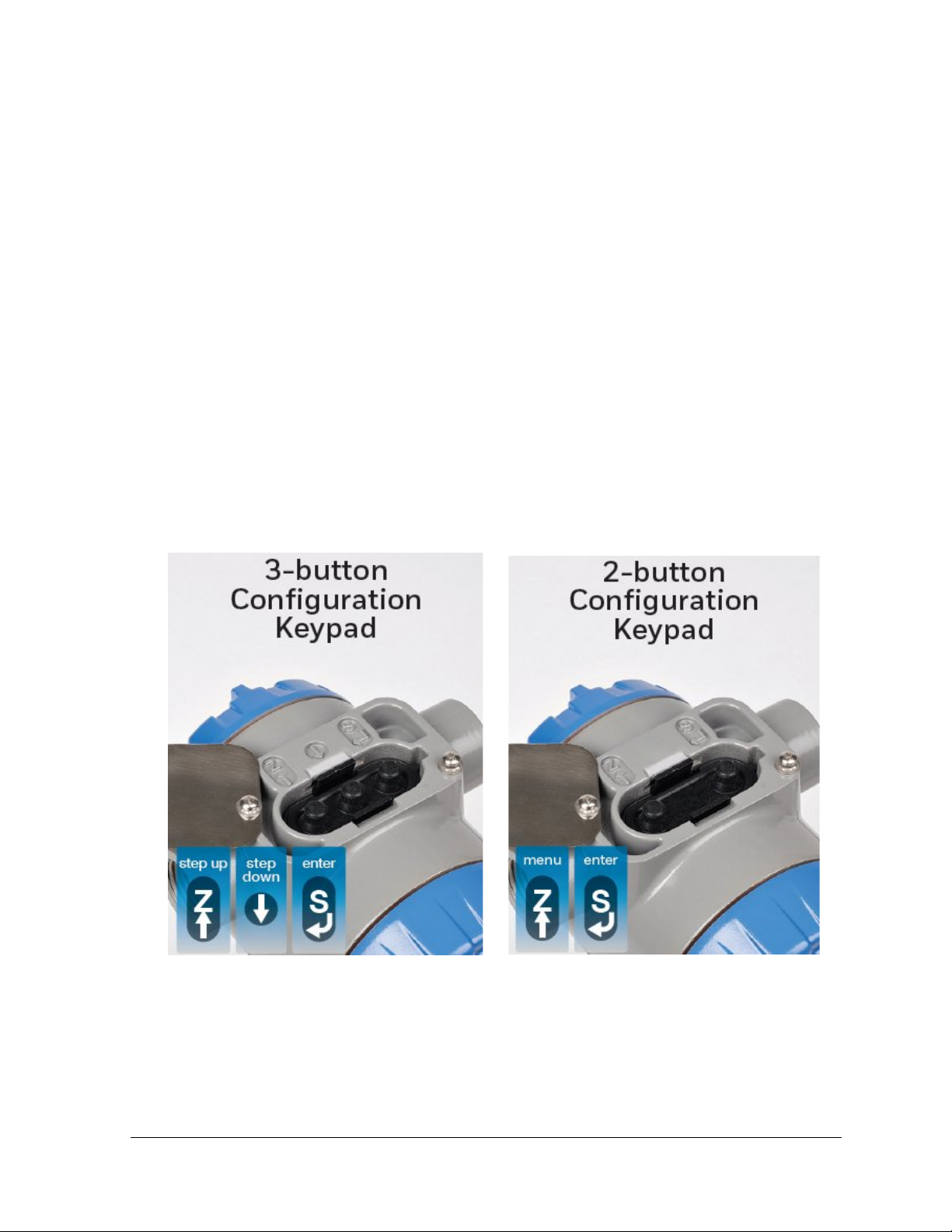
2. The standard transmitter will have a three button assembly, the basic transmitter will have
two button assembly.
3-button Standard ST 700 Transmitter 2-button Basic ST 700 Transmitter
If you have a ST 700 Standard Transmitter use Sections 2 through 12.
If you have a ST 700 Basic Transmitter go straight to Section 13 through 21
Revision 5.0 ST 700 Series HART/DE Option User’s Manual Page 1

Smart Line Pressure ST 700
Standard Models
Basic Models
Dual head DP
STD720/730/770
STD725/735/775
Dual head GP
STG730/740/770
STG735/745/775
Inline GP
STG73L/74L/77L/78L/79L
STG73S/74S/77S/78S/79S
Inline flush GP
STG73P
STG73SP
Dual head AP
STA722/740
STA725/745
Inline AP
STA72L/74L/77L
STA72S/74S/77S
Flush flanged level
STF724/732
STF725/735
Pseudo flanged level
STF72F/73F
STF72P/73P
Remote seal DP/GP
STR73D/74G
STR735D/745G
Transmitter
Configuration
Table 1 - ST 700 Standard and Basic Transmitter Model Types
Page 2 ST 700 Series HART/DE Option User’s Manual Revision 5.0
Communication Protoco ls
HART* version 7, Digitally Enhanced (DE), Fieldbus*
Human-Machine Interface (HMI)
Basic Digital Display:
• Basic display language: English only
Standard Display:
• Two-mode operations: PV display and Menu
Calibration
Manual, 34-ST-25-44 for details.
Single
Approvals
Manual, 34-ST-25-44 for details.
FM, CSA, ATEX, IECEx, SAEx, INMETRO, NEPSI,
Mounting Brackets
Angle/flat carbon steel/304 and 316 stainless steel,
Marine 304 stainless steel, 316 Stainless Steel
2 Introduction to the ST 700 Standard Transmitter
This section is an introduction to the physical and functional characteristics of Honeywell’s ST 700
Standard SmartLine Pressure Transmitter.
2.1 Features and Options
The ST 700 Standard SmartLine Pressure Transmitter is available in a variety of models for
measuring Differential Pressure (DP), Gauge Pressure (GP), and Absolute Pressure (AP). Table 2 lists
the protocols, human interface (HMI), materials, approvals, and mounting bracket options for the ST
700.
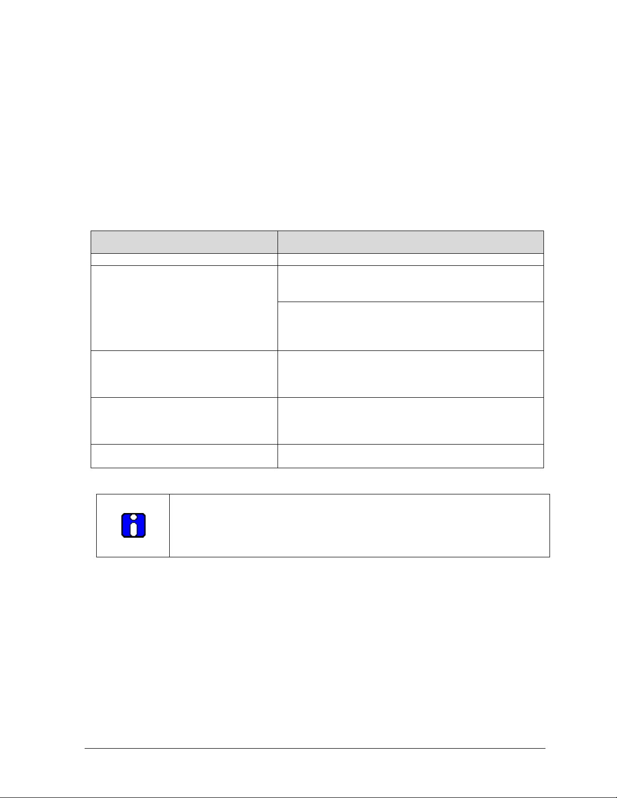
Table 2 – Features and Options
Feature/Option Standard/Available Options
Options (Basic Display)
Refer to the Calibration sections of the
ST 700 SmartLine Transmitters User’s
Refer to the Approvals sections of the
ST 700 SmartLine Transmitters User’s
• Three-button programming (optional)
• Two-button programming (optional)
• Standard display language: English only
GOST and MARINE
The 3-button option is available for the Basic Display.
The 2-button option is available for the Standard Display.
Also, for the Standard Display, the three button reed switch is used only for span &
zero correction and not for the Display navigation.
* The DE and Fieldbus protocols are not supported with the Standard display.
Revision 4.0 ST 700 Series HART/DE Option User’s Manual Page 1
2.1.1 Physical Characteristics
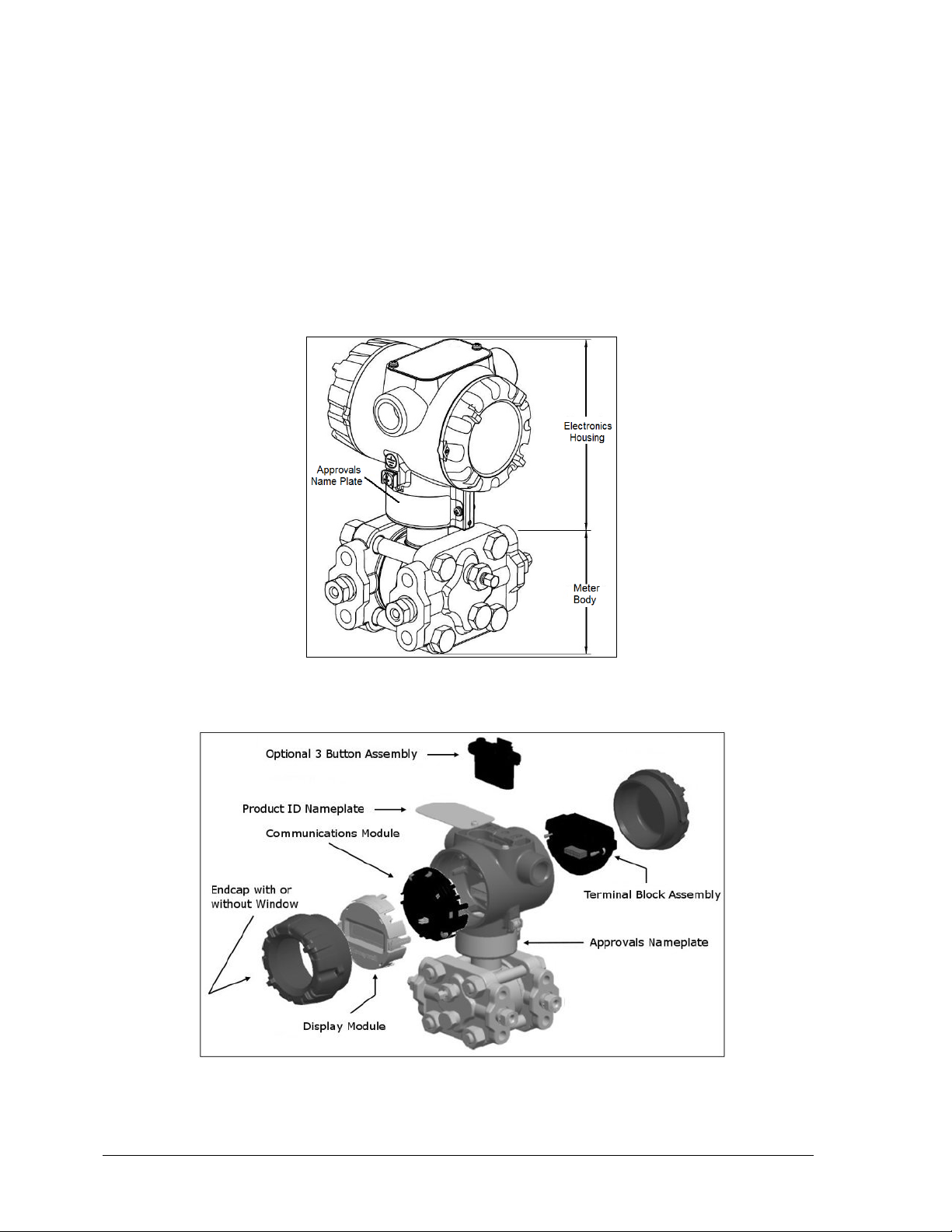
As shown in Figure 1, the ST 700 is packaged in two major assemblies: the Electronics Housing and
the Meter Body. The elements in the Electronic Housing respond to setup commands and execute the
software and protocol for the different pressure measurement types. Figure 2 shows the assemblies in
the Electronics Housing with available options.
The Meter Body provides connection to a process system. Several physical interface configurations
are available, as determined by the mounting and mechanical connections. Refer to the ST 700
SmartLine User’s Manual, Document# 34-ST-25-44 for installation and wiring details.
Figure 1 – ST 700 Standard Major Assemblies
Figure 2 – Electronics Housing Components
Page 2 ST 700 Series HART/DE Option User’s Manual Revision 5.0
• A = Absolute Pressure
• D = Differential Pressure
• F = Flange Mounted
• G = Gauge Pressure
• R = Remote Seals
2.1.2 Functional Characteristics
Functionally, the Transmitter measures process pressure and outputs a signal proportional to the
measured process variable (PV). Available output communication protocols include analog 4 to
20mA, Honeywell Digitally Enhanced (DE) protocol, HART, and FOUNDATION Fieldbus.
An optional 3-button assembly is available to set up and m ak e adjustm ents to the Tr ansm itter. I n
addition, a Honeywell Multi-Communication (MC) Toolkit (not supplied with the Transmitter) can
facilitate setup and adjustment procedures. Certain adjustments can be made through an Experion
Station or a Universal Station if the Transmitter is digitally integrated with Honeywell’s Experion or
TPS/TDC 3000 control system.
An optional 2-button display is also available for configuring / adjusting the Transmitter.
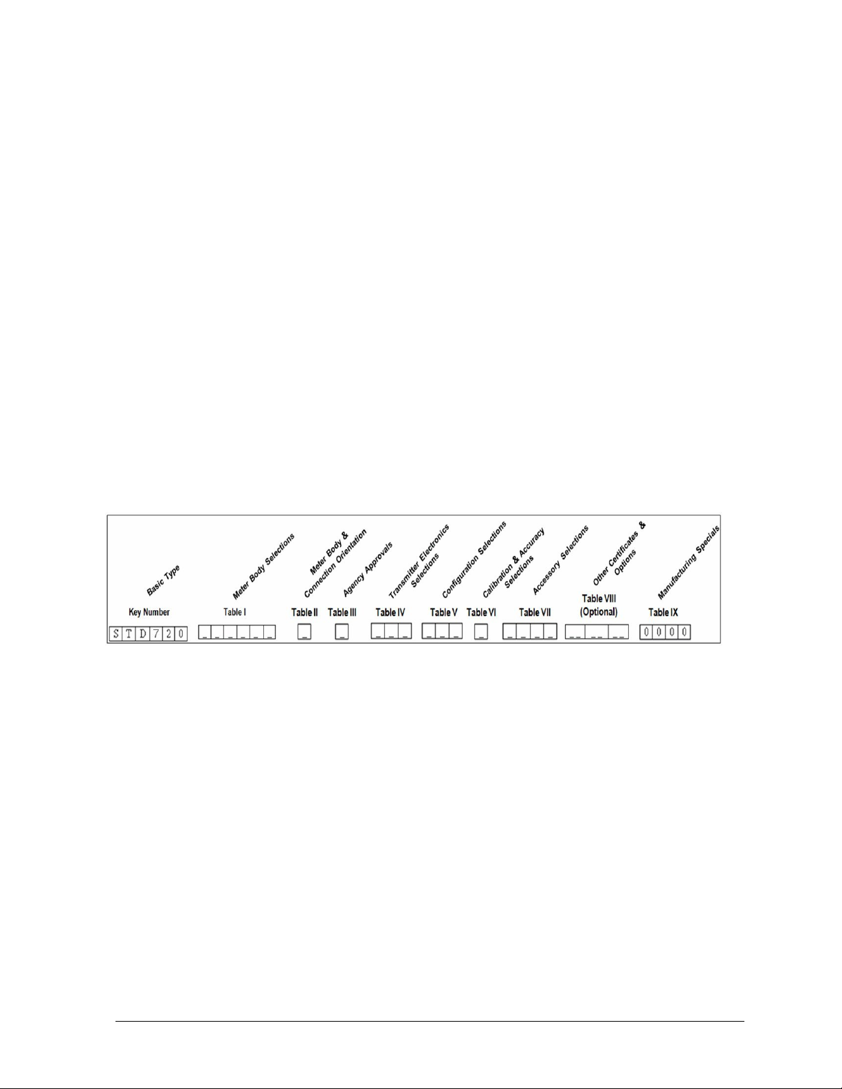
2.2 ST 700 Standard Transmitter Nameplate
The Transmitter nameplate mounted on the top of the Electronics Housing (see Figure 2) lists the
model number, physical configuration, electronics options, accessories, certifications, and
manufacturing specialties. Figure 3 is an example of a typical Differential Pressure (DP) or Gauge
Pressure (GP) or Absolute Pressure (AP) Transmitter name plate. The model number format consists
of a Key Number with several table selections. The Differen tia l Pressu re (DP), Absolute Pressure
(AP), and Gauge Pressure (GP) name plates are essentially the same. However, the DP provides one
additional entry (7 vs. 6 characters) in the Meter Body Selections (Table I) to accommodate the static
pressure rating.
Figure 3 –Typical Standard Transmitter Name Plate Information
You can readily identify the series and basic Transmitter type from the third and fourth digits in the
key number. The letter in the third digit represents one of these basic transm itter ty pes:
For a complete selection breakdown, refer to the appropriate Specification and Model Selection
Guide provided as a separate document.
2.3 Safety Certification Information
An “approvals” name plate is located on the bottom of the Electronics Assembly; see Figure 1 for the
exact location. The approvals name plate contains information and service marks that disclose the
Transmitter compliance information. Refer to Appendix A of the ST 700 SmartLine Transmitters
User’s Manual, Document # 34-ST-25-44 for details.
Revision 5.0 ST 700 Series HART/DE Option User’s Manual Page 3

2.4 Transmitter Adjustments
Zero and Span adjustments are possible in new generation ST 700 Standard SmartLine Pressure
Transmitter by using the optio n a l thr ee -button assembly located at the top of the Electronic Housing
(see Figure 2). However, certain capabilities are limited in the following configurations:
• Without a display: Zero and Span setting only for HART and DE devices.
• With a display: Complete Tra nsmitter configuration is possible for HART & DE devices.
You can also use the Honeywell MCT404/202 Configuration Tool to make any adjustments to an ST
700 Transmitter. The MCT404/202 tool has two applications; MC Toolkit and FDC. Using the MC
Toolkit application you can adjust the ST 700 DE model configuration. Using the Field Device
Configurator (FDC) application, you can adjust the ST 700 HART model configuration. Alternately,
you can use the Honeywell SmartLine Configuration Tool, SCT 3000, for configuring DE models.
Certain adjustm ents can also be made through the Experion or Universal Station if the Transmitter is
digitally integrated with a H oneywell Experion or TPS system.
ST 700 HART models can be configured using Honeywell tools such as Experion in conjunction with
FDM, using DTMs running in FDM or Pactware, or Emerson 375 or 475.
The Standard Display has limited configuration functionality is supported for entering LRV and
URV values.
Page 4 ST 700 Series HART/DE Option User’s Manual Revision 5.0

• Supports optional 3-B utt on c onf iguration and calibration
• Has a limitedl character display
2.5 Display Options –Standard Display
Table 3 – Available Display Characteristics
• Suitable for basic process needs
o
rotation in 90o Increments
bar, mbar, inHg, FTH
o atm, bar, ftH
kgf/cm
Torr, mH
O68F, gf/cm2, inH2O39F, inH2O60F, inH2O68F, inHg0C,
2
2
, kPa, mbar, mmH2O4C, m, mH2O68F, mmHg0C , MPa, Pa, psi,
O4C, cmH2O4C
2
O, mmH2O, MMHG, & PSI
2
Basic Display
Standard Display
• 360
• 2 lines, 16 characters
• Standard units of measurement: Pa, KPa, MPa, KGcm
• Diagnostic messaging
• Square root output indications
• 360o rotation in 90o Increments
• 2 lines, 6 characters
• Standard units of measurement:
• Diagnostic messaging
2
, TORR, ATM, inH2O,
2.6 Optional 3-Button Assembly (Basic Display)
The optional 3-Button Assembly for the Basic Display provides the following features and
capabilities:
• Increment, decrement, and enter key functions.
• With the menu-driven display:
o Comprehensive on-screen menu for navigation.
o Transmitter c on f ig ur a tio n .
o Transmitter c a lib ration
o Display configuration.
o Set zero and span parameters.
The optional 3-button assembly provides the following benefits:
• Opportunity for immediate reaction with minimal disruptions
• Improved maintenance time
• Potential savings on hand-held units
• Suitable for all environments: hermetically sealed for long life in harsh environments
• Suitable for use in all electrical classifications (flameproof, dustproof, and intrinsically safe)
Revision 5.0 ST 700 Series HART/DE Option User’s Manual Page 5
If you are using the optional external two-butt o n asse mbly with the
2.7 Optional Integrated Two-Button Assembly (Standard Display)
The Standard Display does not support all the transmitter configurations and has limited features. The
optional 2-Button Assembly for the Standard Display provides the following features and capabilities:
• Menu and enter key functionality.
• With the menu-driven display:
o Comprehensive on-screen menu for navigation.
o Transmitter configuration: enter LRV, enter URV and Loop Test.
o Transmitter c a lib ration
o Display configuration
o Set zero and span parameters.
Standard Display then you can perform all the above operations without
removing external glass cap using the external buttons
Lower range value (LRV): A display parameter (Standard display), which
allows users to enter the measuring value for which the analog output will
be scaled to 4mA.
Upper range value (URV): A display parameter (Standard display), which
allows users to enter the measuring value for which the analog output will
be scaled to 20mA.
Page 6 ST 700 Series HART/DE Option User’s Manual Revision 5.0
3 Communication Model for ST 700 Standard
Transmitter
3.1 Overview
The ST 700 Standard SmartLine Pressure Transmitter can be configured for operation with
Honeywell’s Digitally Enhanced (DE) communication protocol, HART version 7, and Fieldbus
communication. This manual addresses the processes to configure and calibrate a Transmitter for DE
and HART communication. Refer to the ST 700 SmartLine FF Transmitter with FOUNDATION
Fieldbus Option Installation & Device Reference Guide, Document # 34-ST-25-48 for Fieldbus
details.
3.2 Digitally Enhanced (DE ) Mode Communication
Although it is unnecessary to put a control loop in manual mode before communicating
with a Transmitter operating in DE mode, caution is required if there is potential for error in
identifying the operating mode.
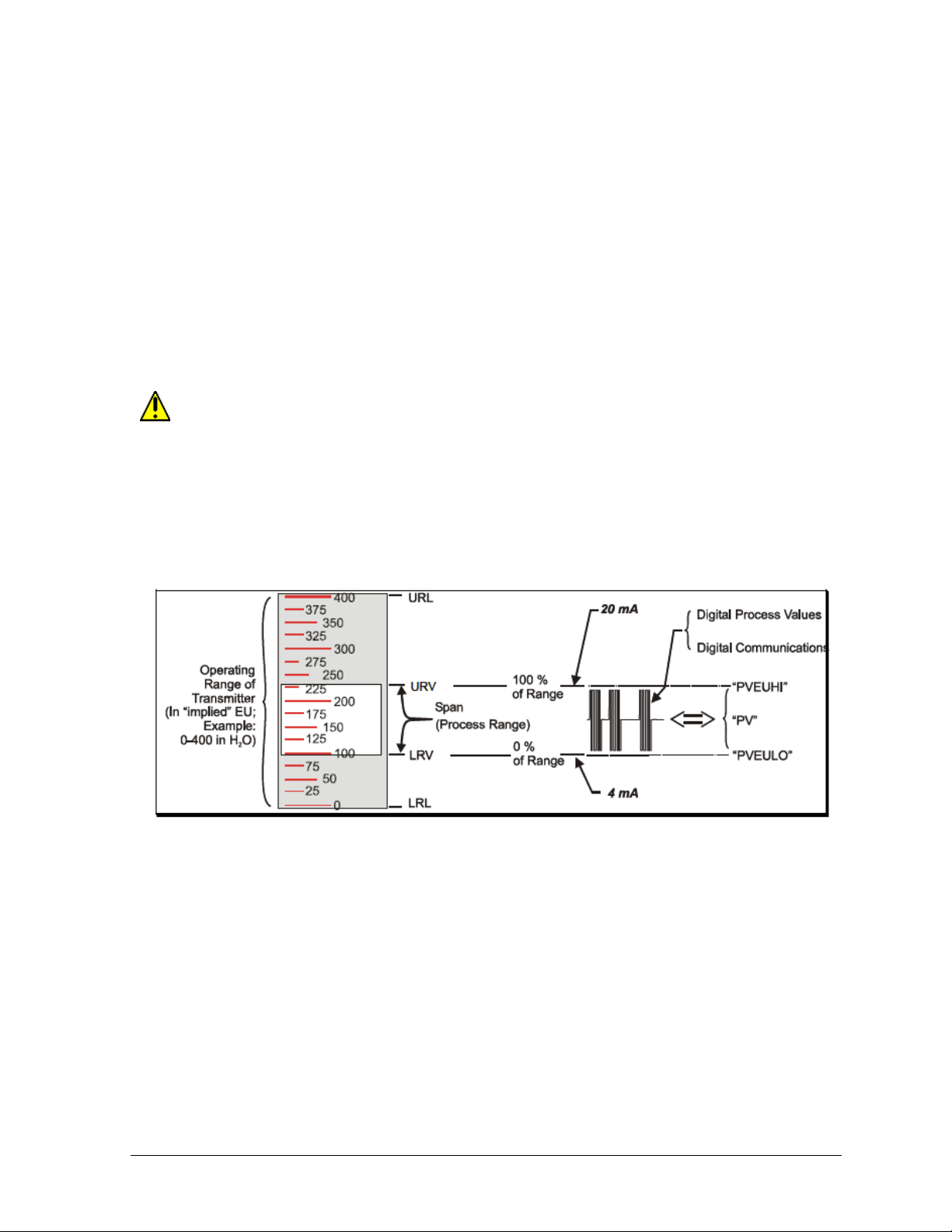
In DE mode, the PV is available for monitoring and control purposes; and the meter body temperature
(secondary variable) is availab le for monitoring purposes only.
Much of the operation in the Digitally Enhanced (DE) mode is similar to that of analog operation.
The essential characteristics of DE mode operation are shown in Figure 4.
Figure 4 – DE Mode Value Scaling
As indicated at the r ig ht o f Figure 4, output values of process variables, as well as com m u nications
are transferred to a receiving device digitally. The digital coding is Honeywell proprietary, which
requires the use of DE-capable Honeywell control equipment.
The use of DE mode offers several advantages:
• Process Safety: Unlike analog mode, communications devices do not bump the PV value.
• Accuracy: requires less maintenance.
• Digital communication: Relatively immune to small variations in circuit resistance or supply
voltage.
• Facilitates Maintenance Tasks: Honeywell control systems include operating displays that
enable direct communication with transmitters operating in DE mode.
Revision 5.0 ST 700 Series HART/DE Option User’s Manual Page 7
3.3 HART Mode Communication
When using MCT404/202,before connecting to a HART transmitter, verify that the FDC
application is used and not the MC Toolkit application. When you use the MC Toolkit
application, the MCT404/202 is set for DE communications, where the current amplitude can
bump process variables in either point-to-point or in the multi-drop mode in HART.
Transmitters with HART capability have features that vary among manufacturers and with the
characteristics of specific devices. The FDC software application executing on the MCT404/202
supports the HART Universal, Common Practice and Device Specific Commands which are
implemented in the Honeywell Transmitters.
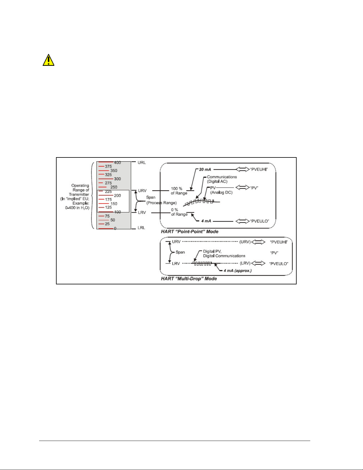
As indicated in Figure 5, the output of a Transmitter configured for HART protocol includes two
primary modes:
Figure 5 – HART Point-to-Point and Multi-drop Value Scaling
• Point-to-Point Mode: Where one Transmitter is connected via a two-conductor, 4-20mA
current loop to one receiver.
• Multi-Drop Mode: Where several Transmitters are connected through a two-conductor
network to a multiplexed receiver device.
In point-to-point mode, the value of the primary Process Variable (PV) is represented by a 4-20mA
current loop, almost identical to that of a Transmitter operating in analog mode. In this case, however,
the analog signal is modulated by Frequency Shift Keying (FSK), using frequencies and current
amplitude that do not affect analog sensing at the receiver. The accuracy of the analog level must be
precisely controlled for accurate sensing. HART communication will not bump process variables.
In multi-drop mode, up to 16 transmitters in HART 5 (addresses 0-15) and up to 64 transmitters in
HART6/7 (addresses 0-63) can exist on the two-conductor network.
Page 8 ST 700 Series HART/DE Option User’s Manual Revision 5.0

correction
4 Configuration Tools and Interfaces for
ST 700 Standard T ransmitter
4.1 Overview
This section describes the tools and interfaces involved in configuring a new ST 700 Standard
SmartLine Pressure Transmitter for HART or DE communication operation. The information in this
section also applies to adjusting the configuration of a Transmitter that has been in operation and
updating one that is currently in operation.
4.2 Pre-requisites
The information and procedures in this manual are based on the assumption that personnel
performing configuration and calibration tasks are fully qualified and knowledgeable in the use of the
Honeywell MC To olkit or MCT404/202. The name MC Toolkit or Toolkit and MCT404/202 are used
interchangeably as MCT404/202 is the model name for the Honeywell MC Toolkit product.
Furthermore, we assume that the reader is intimately familiar with the ST 700 family of SmartLine
Pressure Transmitters and thoroughly experienced in the type of process application targeted for
Transmitter deployment. Therefore, detailed procedures are supplied only in so far as necessary to
ensure satisfactory completion of configuration tasks.
4.3 Application Design, I ns tallation, Startup, and Operation
The ST 700 SmartLine Pressure Transmitters User’s Manual, Document # 34-ST-25-44, provides the
details for application design, installation, and startup; see Table 4 for topics.
Table 4 – User Manual Related Topics
ST 700 SmartLine Pressure Transmitters User’s Manual
Section 2.
Application Design
Safety and accuracy
Diagnostics messages
Design consideration
Section 3. Installation and Star tup Section 4. Operation
Site evaluation
Toolkit issues
Display installation concerns
Transmitter mounting & zeroPiping & wiring
Startup tasks and procedures
Three-button option (Basic
Display)
Two-button option (Standard
Display)
Failsafe direction setup
Monitoring displays
4.3.1 Organization
This information in this section is arranged in the following sequence:
• MC Toolkit participation in ST 700 Transmitter Setup and Configuration:
o Physical circuit connection s
o Application components
o Configuration for Analog, DE, and HART operation
• ST 700 Transmitter:
o Basic displays (3-buttons)
o Standard Displays (2-buttons)
o Health indications
o Ability to be configured and operate in a process system
Revision 5.0 ST 700 Series HART/DE Option User’s Manual Page 9

4.4 MC Toolkit Participation
Before using the MC Toolkit, ensure that you are aware of the potential consequences of
each procedure, and that you use appropriate safeguards to avoid possible problems. For
example, if the Transmitter is an element in a control loop, the loop needs to be put in manual
mode, and alarms and interlocks (i.e., trips) need to be disabled, as appropriate, before
starting a procedure.
4.4.1 MC Toolkit Software Applications
The MC Toolkit has two software applications to work with ST 700 Standard SmartLine Pressure
Transmitters:
• Field Device Configurator (FDC): This application is used for configuring, calibrating,
monitoring, and diagnosing HART devices. FDC conforms to the IEC 61804-3 EDDL
(Electronic Data De scription Lang uage) standard specification. The FDC applica tion is an open
solution that supports devices with a registered device description (DD) file compatible with
HART Communication Foundation (HCF) requirements.
• MC Toolkit: This application is used for configuring, calibrating, monitoring, and diagnosing
Honeywell Digitally Enhanced (DE) devices.
Details for work in g with the MC Toolkit are provided in the MC Tookit User Manual, Document #
34-ST-25-20 (MCT202) or #34-ST 25-50 (MCT404). In subsequent sections of this manual, explicit
operating instructions are provided only in so far as necessary to complete required tasks and
procedures.
4.4.2 Configuration Databases
The MC Toolkit is used to establish and/or change selected operating pa ram eters in a Transm itte r
database.
4.4.3 Configuration
Configuration can be accomplished both online and offline with the Transmitter powered up and
connected to the MC Toolkit. Online configuration immediately changes the Transm itter operat ing
parameters. For offline configuration, Transmitter operating characteristics are entered into Too lkit
memory for subsequent downloading to a Transmitter.
When you set up or configure a Transmitter, it can take up to 30 seconds for the value
to be permanently stored. If you change the Sensor Type or ID and the Transmitter power is
interrupted before the change is copied to nonvolatile memory, the changed value will not be
moved to nonvolatile memory.
When Sensor Type or ID is changed, the associated parameters (Field calibration data,
Sensor bias value, disable CVD option, default CVD data and disable match PV if it is dual
input model) which are specific to that sensor input, are written to default values.
Page 10 ST 700 Series HART/DE Option User’s Manual Revision 5.0
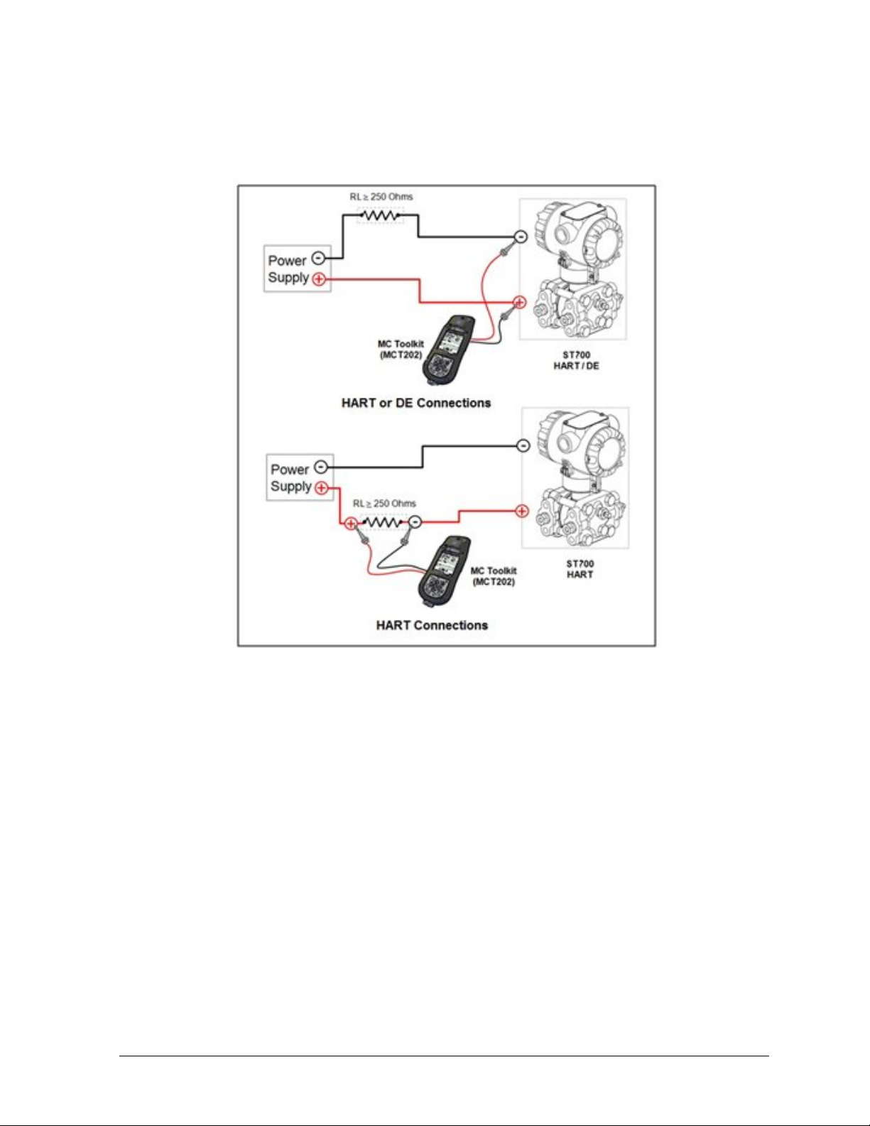
4.4.4 MC Toolkit–Transmitter Electrical/Signal Connections
Figure 6 displays how to connect the MC Toolkit directly to the terminals of a HART or DE
Transmitter (top), and a HART-only Transmitter (bottom).
Figure 6 – MC Toolkit-Transmitter Electrical/Signal Connections
Revision 5.0 ST 700 Series HART/DE Option User’s Manual Page 11

5 DE Transmitter Configuration for
ST 700 Standard Transmitter
5.1 Configuration Personnel Re quirements
The configuration processes in this section reflect the assumption that you will use the Honeywell
MC Toolkit Configuration Tool to configure an ST 700 Standard SmartLine Pre ss ure T ransm it ter.
The MC Toolkit application is used to configure the Honeywell ST 3000 Pressure Transmitter, the
STT 3000 Smart Temperature Transmitters, as well as the ST 700 Standard SmartLine Pressure
Transmitter. Throughout, the term Transmitter means the ST 700 Standard SmartLine Pressure
Transmitter.
The other tools that support the DE Transmitter configuration are the SmartLine Configuration
Toolkit (SC T 3000), Experion PKS, and Smart Field Communicator (SFC).
5.2 MC Toolkit Software Application Overview
Each new ST 700 Standard SmartLine Pressure Transmitter is shi pped from the factory with a basic
configuration installed. This basic configuration must be edited or revised to meet the requirements of
your process system.
The MC Toolkit application supports both online and offline configuration.
• Online operation allows you to establish communication with a DE Transmitter for the
following tasks:
o Upload a Transmitter database.
o Configure Transmitter para meters.
o Calibrate a Transmitter.
o Execute diagnostics.
o Save a configuration to a file.
• Offline operation allows you to click a basic template, edit the parameters and download to a
Transmitter after establishing communication with it. Parameter updates can also be saved in
a file without actually downloading them to a Transm i tte r.
Specific operating details for the MC Toolkit displays are prov ided in Section 3.5, “MC Toolkit
Application Software Display Conventions,” of the MC Toolkit User Manual, Document # 34-ST-2520 (MCT202) or #34-ST-25-50 (MCT404), for the following:
• Navigation
• The MC Toolkit Menu Bar
• File Menu
• Modem Menu
• Help Menu
• Data Entry and Display
Page 12 ST 700 Series HART/DE Option User’s Manual Revision 5.0
5.3 DE Transmitter Online Conf iguration
Online configuration consists of establishing communication between the MC Toolkit and a
Transmitter configured fo r DE communication. Each Transmitter has a configured database, whether
new from the factory, a spare, or one to be reconfigured. In any case, the MC Toolkit application is
used to upload the existing configuration from the Transmitter for review and editing.
5.3.1 Uploading a Transmitter Configuration
1. Connect a DE Transmitter to the MC Toolkit. Ensure that both devices have power applied.
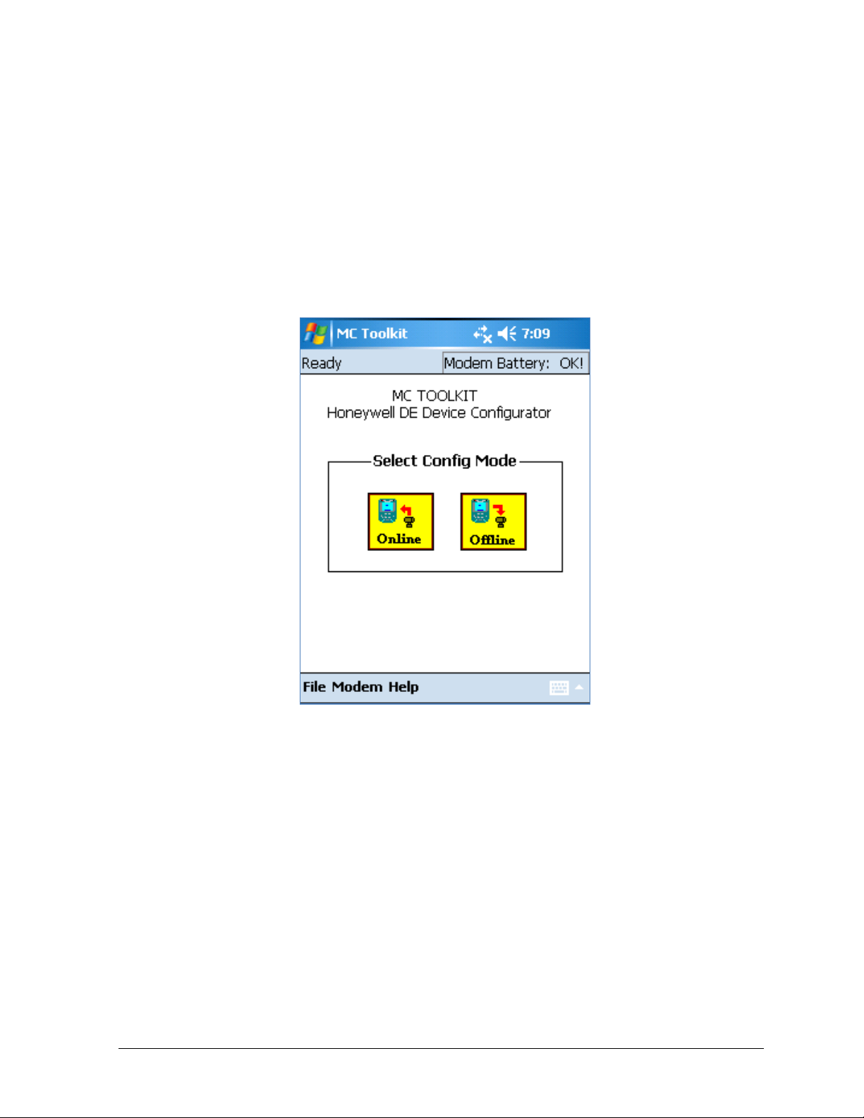
2. To start the MC Toolkit application, click Start / MC Toolkit on the MC Toolk it /
MCT404/202. The MC TOOLKIT homepage will be displayed.
3. Click the Online button, and establish communication between the Toolkit and the
Transmitter.
4. When the warning message for connecting to a DE device appears, click OK.
5. Process the three warning pop-ups as appropriate, and then click OK in the Put loop in
Manual… pop-up. The DE QUICK MONITOR bo x w ill be displayed.
Revision 5.0 ST 700 Series HART/DE Option User’s Manual Page 13
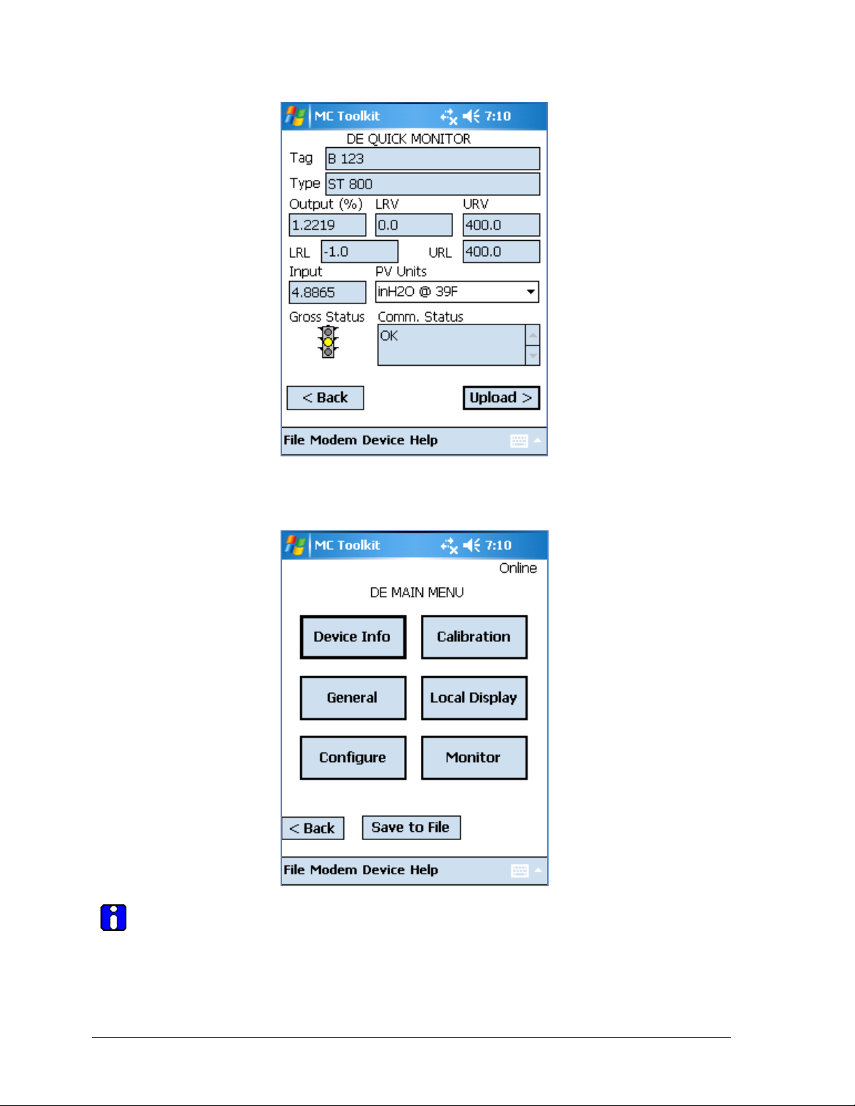
6. Click Upload. A progress bar will be displayed on the DE QUIC K M ON ITOR box, and
when the upload is complete, the DE MAIN MENU will be displayed.
A confirmation request message will be displayed if you click <Back for a Transmitter
that was previously set to Output Mode during calibration, and was not subsequently
cleared. If you confirm the message (Yes answer), the display will exit the DE MAIN MENU.
Page 14 ST 700 Series HART/DE Option User’s Manual Revision 5.0
Tag ID
R/W
User ID up to 8 alphanumeric characters.
Type
R
Manufacturer’s device t ype identif ier
Firmware Version
R
Manufacturer’s firmware version identifier
PROM ID Number
R
PROM ID Number
Scratch Pad
R/W
Up to 32 alphanumeric characters
5.3.2 Device Information Configuration
In this and subsequent procedures, the notations R for read only and R/W for read/write are used to
indicate if a parameter can be edited.
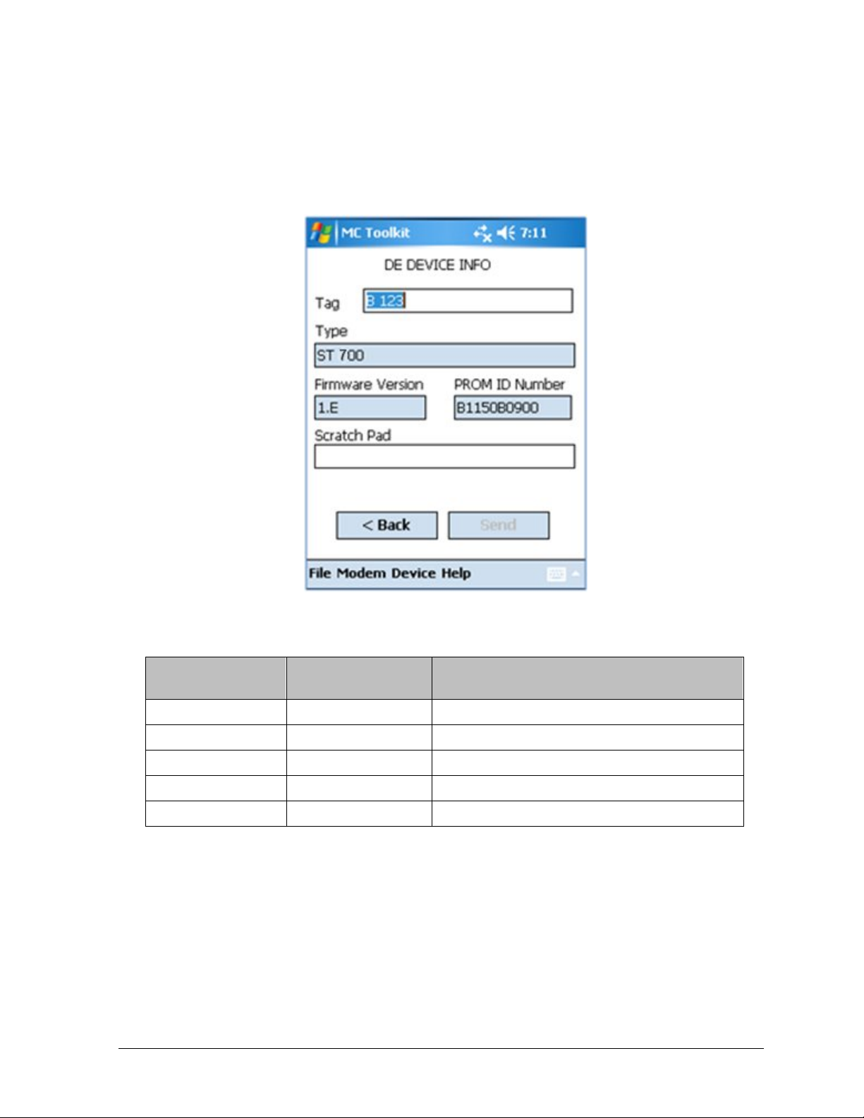
1. On the DE MAIN MENU, click Device Info. The DEVICE INFO box will be displayed.
2. Configure device information according to Table 5.
Table 5 – Device Information Parameters
Parameter
Read (R) or
Read/Write (R/W)
Configuration Details
3. Click the Back button to return to the DE MAIN MENU.
Revision 5.0 ST 700 Series HART/DE Option User’s Manual Page 15
Read (R) or
Read/Write (R/W)
Failsafe (FS) direction: upscale or downscale, switch
details.
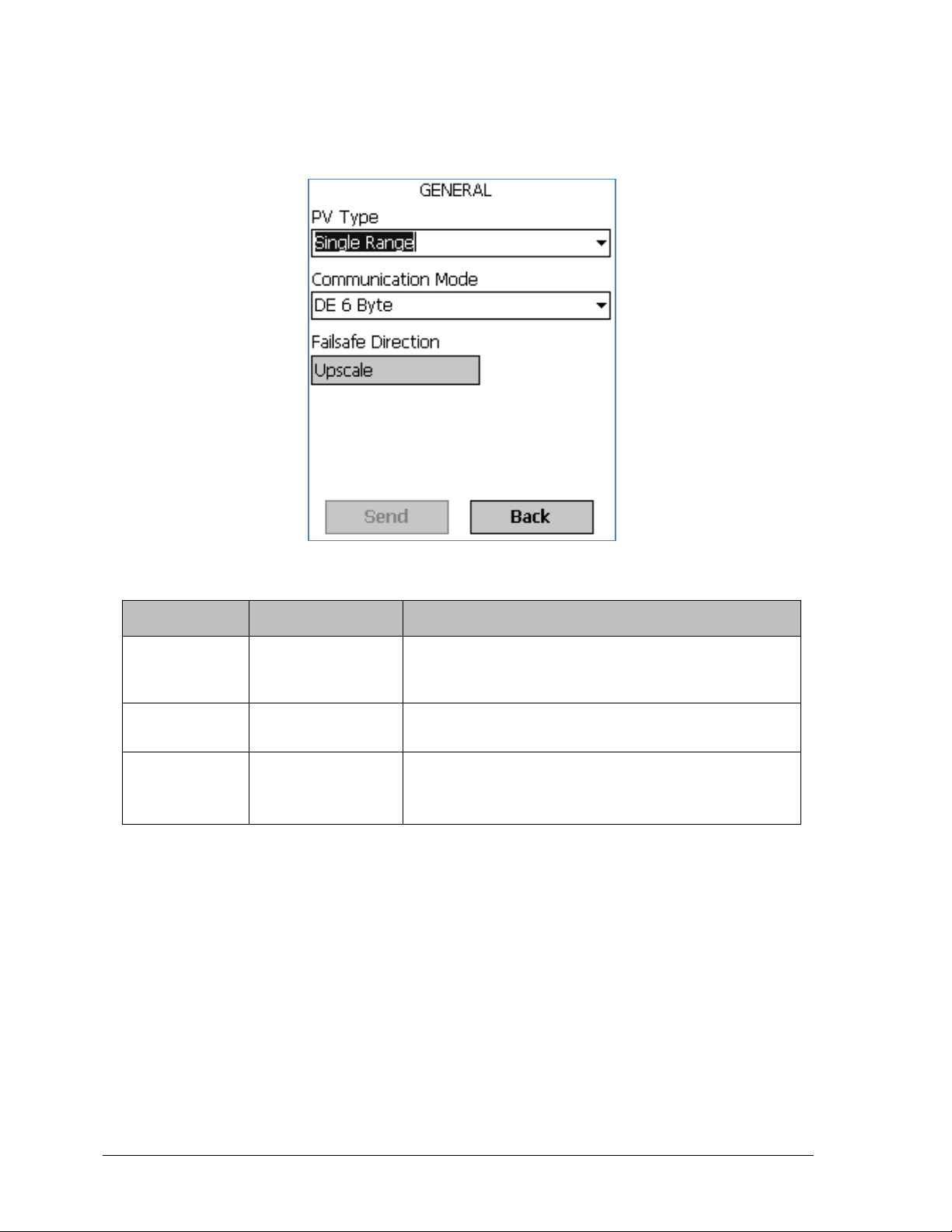
5.3.3 General Configuration Par ameters
Click the General button on the DEVICE MAIN MENU page, and configure parameters according
to Table 6.
Table 6 – General Configuration Parameters
Parameter
PV Type
Communication
Mode
FS Direction
R/W
R/W
R
Configuration Details
Dual Range Smart Transmitter Digital Communications
(STDC) or Single Range or Single Range with
secondary variable (SV).
Analog, DE 4-byte, or DE 6-byte
selectable on the electronics module. Se e the ST 700
SmartLine Transmitter User Manual, 34-ST-25-44 for
Click the Back button to return to the DE MAIN MENU.
Page 16 ST 700 Series HART/DE Option User’s Manual Revision 5.0
 Loading...