

Honeywell SS500 Installation Instructions Manual
Installation Instructions for the
SS500 Series Temperature Compensated
Hall Effect Sensors
WARNING
PERSONAL INJURY
DO NOT USE these products as safety or
emergency stop devices or in any other application
where failure of the product could result in personal
injury.
Failure to comply with these instructions could
result in death or serious injury.
CAUTION
ELECTROSTATIC DISCHARGE DAMAGE
This component is sensitive to electrostatic discharge
(ESD). Take normal ESD precautions in handling this
product to prevent ESD-induced damage and/or
degradation.
Failure to comply with these instructions will
result in product damage.
CAUTION
WAVE SOLDER DAMAGE
DO NOT wave solder this product. Wave soldering
may negatively affect the sensor performance and
reliability. Subjecting the sensor to wave soldering
will void Honeywell’s warranty.
Failure to comply with these instructions will
result in product damage.
ABSOLUTE MAXIMUM RATINGS*
Supply Voltage -1 to +30 VDC
Voltage externally
applied to output
Output ON Current See Table A.
Operating Temperature -50 to +160°C
Storage Temperature -65 to +160°C
Magnetic Flux No limit. Circuit cannot be
* Absolute maximum ratings are the extreme limits that the
device will withstand without damage to the device.
However, the electrical and mechanical characteristics are
not guaranteed as the maximum limits (above
recommended operating conditions) are approached, nor
will the device necessarily operate at absolute maximum
ratings.
SOLDERING INSTRUCTIONS
Honeywell recommends an infrared reflow process
with peak temperatures not to exceed 245°C (473°F)
for 10 seconds maximum.
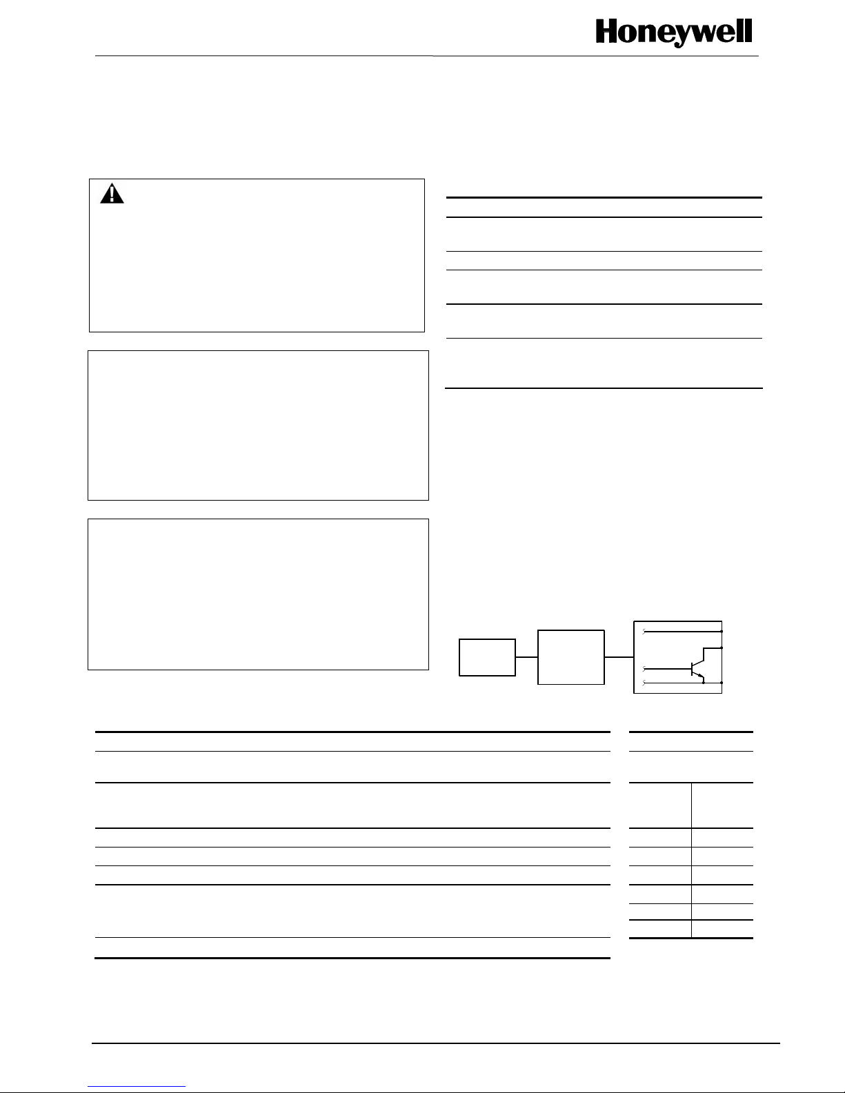
BLOCK DIAGRAM
HALL
SENSOR
TRIGGER
CIRCUIT
AND
AMPLIFIER
ISSUE 5
PK 80079
+30 VDC max. (OFF only)
-0.5 VDC min. (OFF or ON)
(-67 to +320°F)
(-85 to +320°F)
damaged by magnetic
overdrive.
Vs (+)
OUTPUT
(0) N.H.
GROUND (-)
OPERATING CHARACTERISTICS (over Operating Voltage and Temperature, unless otherwise noted)
Min. Typ. Max. Remarks TABLE A
Supply Voltage 3.8 ⎯ 30 VDC
Current Consumption ⎯ ⎯ 10 mA
Output Voltage (operated) ⎯ 0.15 0.40 Sinking 20 mA max. -1 to 24 50
Output Current (operated) ⎯ ⎯ 20 mA 24 to 25 37
Output Leakage Current (released) ⎯ ⎯ 10 µA 25 to 26 33
Output Switching Time VCC = 12 V, 26 to 27 28
Rise, 10 to 90% ⎯ .05 µs 1.5 µs RL = 1.6 K Ω, 28 to 29 19
Fall, 90 to 10% ⎯ .15 µs 1.5 µs CL = 20 pF 29 to 30 15
Operating Temperature Range -40°C to +125°C (-40°F to 302°F)
Note: To prevent damage to the leads, SS500 Series surface mounted sensors are
supplied only on tape and reel.
Sensing and Control
Output Current
Absolute Limits
Supply
Voltage
Output
Current
Max. mA
SS500 Series
ISSUE 5 PK 80079
MAGNETIC CHARACTERISTICS
SS511AT SS513AT SS541AT SS543AT SS549AT SS561AT SS566AT
Magnetic Type Bipolar Bipolar Unipolar Unipolar Unipolar Latching Latching
-40°C Max. Op. 70 140 135 215 435 110 200
Min. Rel. -70 -140 20 80 210 -110 -200
Min. Dif. 15 20 15 25 30 50 200
0°C Max. Op. 65 140 117 190 400 90 185
Min. Rel. -65 -140 20 80 230 -90 -185
Min. Dif. 15 20 15 25 30 50 200
25°C Max. Op. 60 140 115 180 390 85 180
Min. Rel. -60 -140 20 75 235 -85 -180
Min. Dif. 15 20 20 25 30 50 200
85°C Max. Op. 60 140 120 180 400 85 180
Min. Rel. -60 -140 15 70 215 -85 -180
Min. Dif. 12 20 15 15 30 50 190
125°C Max. Op. 65 140 123 190 410 100 180
Min. Rel. -65 -140 15 60 200 -100 -180
Min. Dif. 12 20 8 10 30 50 160
150°C Max. Op. 70 140 125 200 420 110 185
Min. Rel. -70 -140 10 55 185 -110 -185
Min. Dif. 10 20 5 5 30 50 140
NOTICE
Bipolar Hall effect sensors may have an initial output in either the On or Off state if powered up with an
applied magnetic field in the differential zone (applied magnetic field > Brp and < Bop). Honeywell
recommends allowing 10 µsec for output voltage to stabilize after supply voltage has reached 5 volts.
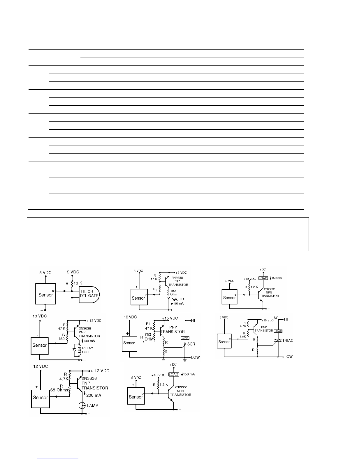
INTERFACE DIA GRAMS
2 Honeywell • Sensing and Control For application help: call 1-800-537-6945
 Loading...