

Honeywell SS4-A HART User Manual

Page 1 of 14
User Guide
SS4-A HART
Page 2 of 14
Revision Histor y
Author Revision Date Comments
T. Lapp A April 19, 2013 Initial release

Page 3 of 14
Table of Contents
1 Introduction .................................................................................................. 4
2 4-20 ma of SS4 ............................................................................................. 4
3 Supported HART Commands ..................................................................... 5
3.1 Command 0 .......................................................................................................... 5
3.2 Command 1 .......................................................................................................... 6
3.3 Command 2 .......................................................................................................... 6
3.4 Command 3 .......................................................................................................... 7
3.5 Command 6 .......................................................................................................... 8
3.6 Command 7 .......................................................................................................... 8
3.7 Command 8 .......................................................................................................... 9
3.8 Command 12 ........................................................................................................ 9
3.9 Command 13 ........................................................................................................ 9
3.10 Command 14 ...................................................................................................... 9
3.11 Command 15 .................................................................................................... 10
3.12 Command 16 .................................................................................................... 11
3.13 Command 20 .................................................................................................... 11
3.14 Command 50 .................................................................................................... 11
4 LED Indication ............................................................................................ 12
5 HART Module Address .............................................................................. 12
6 HART Module Mounting ............................................................................ 12
7 HART Module Connections ....................................................................... 13
Page 4 of 14
1 Introduction
The Fire Sentry FSCHCOM-SS4
module is a piggy-back device that
allows SS4-series flame detectors
to communicate with a HART
Network Master. The HART module
may be considered to be a protoc ol
converter. The flame detector itself
communicates to external devi ces
with the FireBus-I proprietary
protocol. This HART module obtains
alarm and fault status using FireBusI, and then upon receiving a HART
command will respond to the HART
master by re t urning the necess ar y
information. Communication with the master requires that the request that
matches the short address (assigned by the rotary switch) or long address (a
combinat ion of device type and s er ial number).
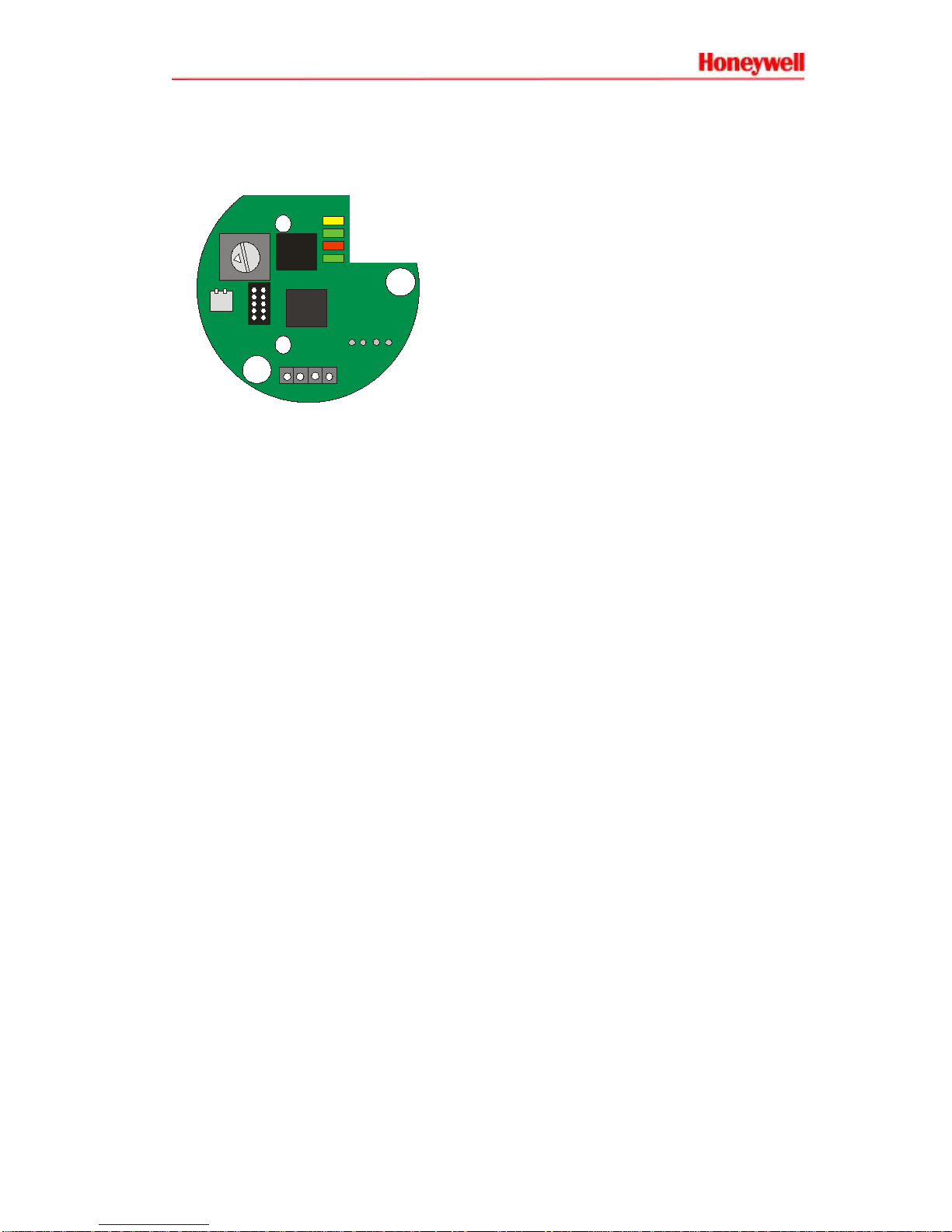
Pin #2 and Pin #3 of J102 of this module are used for HART communication.
Current-loop 4-20 ma is sourced from Pin #2 when switches at S100 are ON, and
ground is the current-return poi n t. See below for connect ion details.
2 4-20 ma of SS4
This FSCHCOM-SS4 is providing 4-20ma analog value as well as HART protocol
simultaneously. In single drop configuration (I=One master to One Device) the
analog 4-20ma provide the following information.
0 ma : PCB fault, Voltage fault, temperature fault, relay fault.
2 ma : Optical Self Test fail & Lid Off fault.
4 ma : Normal.
20 ma : Alarm.
D105 LED
D103 LED
D104 LED
D102 LED
J102
J101
12
3
4
1234
RSW10 0
S10 0
Page 5 of 14
3 Supported HART Commands
The SS4-A HART module supports the commands enumerated below.
3.1 Comm a nd 0
Use command 0 to read Unique Identifier.
Response to command 0:
Manufacturer ID: Hex 6042 String FSCHCOM
Product ID: Hex E180
Polling address is assigned by rotary switch RSW100 ( 0 , 1, 2, 3, 4, 5, 6, 7, 8, 9,
A, B, C, D, E, F).
Placing RSW100 to position 1,2,3.. to F, you are putting the devices in hardware
address mode. Hardware address will over-ride soft war e address.
Placing RSW100 to position 0, you are putting the devices in software addressing
mode.
You can use command 6 to write polling address to the FSCHCOM module.
Once software polling address is written into the FSCHCOM, the address is
saved into flash memory until ov er wr i tten by next comm an d 6.
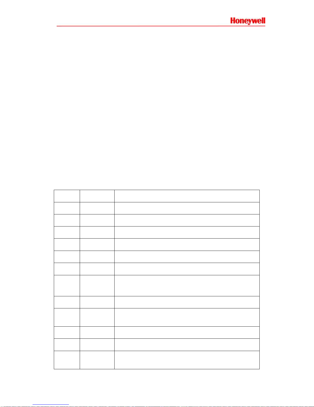
Byte Format Description
0 Unsigned 8 Must be Decimal 254 (Hex FE)
1 to 2 Code Device Type Hex E1 80
3 Unsigned 8 Minimum number of preambles byte from master= 5
4 Unsigned 8 HART Major Revision = 7
5 Unsigned 8 Device Revision Level = 0
6 Unsigned 8 Software Revision = 1
7 Unsigned 8 Bit 7,6,5,4,3 Hard ware revision = 0x10
Bit 2,1,0 physical signal code 0x01
8 Unsigned 8 Flag = 0. N/A
9 to 11 Unsigned
24
Device ID unique from manufacturer
12 Unsigned 8 Mini m um number o f preambles byte to m as t er = 5
13 Unsigned 8 Maximum number of device variable = 4
14 to 15 Unsigned
16
Configuration Change Counter = 0. No user configurtion
 Loading...