


HONEYWELL SS 411 A Datasheet
Installation Instructions for the
SS400 Series Temperature Compensated
Digital Hall-Effect Sensor ICs
ISSUE 6
PK 88700
GENERAL INFORMATION
CAUTION
ELECTROSTATIC
DISCHARGE DAMAGE
This component is sensitive
to electrostatic discharge
(ESD). Take normal ESD
precautions in handling this
product to prevent ESDinduced damage and/or
degradation.
Failure to comply with
these instructions may
result in product damage.
ELECTROSTATIC
SENSITIVE
DEVICES
DO NOT OPEN OR HANDLE
EXCEPT AT A
STATIC FREE WORKSTATION
ESD SENSITIVITY:
CLASS 3
CAUTION
CAUTION
IMPROPER SOLDERING
Ensure leads are supported during any forming/ shearing
operation so that they are not stressed inside the plastic
case.
Limit exposure to high temperatures.
Failure to comply with these instructions may result in
product damage.
CAUTION
IMPROPER CLEANING
Do not use pressure wash. High-pressure stream could force
contaminants into the package.
Failure to comply with these instructions may result in
product damage.
Characteristic
Parameter
Supply voltage
-1 Vdc to +30 Vdc
Voltage externally
applied to output
+30 Vdc max. (OFF only)
-0.5 Vdc min. (OFF or ON)
Output ON current
see Table 2
Operating temperature
-40 °C to 150 °C [-40 °F to 302 °F]
Storage temperature
-50 °C to 150 °C [-58 °F to 302 F]
Magnetic flux
no limit; circuit cannot be damaged
by magnetic overdrive
NOTICE
Absolute maximum ratings are the extreme limits that the
device will withstand without damage to the device.
However, the electrical and mechanical characteristics are
not guaranteed as the maximum limits (above
recommended operating conditions) are approached, nor
will the device necessarily operate at absolute maximum
ratings.
Supply Voltage
Output Current
-1 Vdc to 24 Vdc
50 mA max.
24 Vdc to 25 Vdc
37 mA max.
25 Vdc to 26 Vdc
33 mA max.
26 Vdc to 27 Vdc
28 mA max.
27 Vdc to 28 Vdc
24 mA max.
28 Vdc to 29 Vdc
19 mA max.
29 Vdc to 30 Vdc
15 mA max.
Characteristic
Min.
Typ.
Max.
Note
Supply voltage
3.8 Vdc
30 Vdc
Current consumption
10 mA
Supply current (operated at 25 °C, Vs = 5 V)
6.5 mA
Output voltage (operated)
0.40 Vdc
sinking, 20 mA max.
Output current (operated)
20 mA
Output leakage current (released)
10 A
Output switching time:
rise, 10% to 90%
fall, 90% to 10%
0.05 s
0.15 s
1.5 s
1.5 s
VCC = 12 V,
RL = 1.6 k ,
CL = 20 pF
SOLDERING/ASSEMBLY
PC board wave soldering temperature is 250 °C to 260 °C
[482 °F to 500 °F] peak for 3 s max.
CLEANING
Table 1. Absolute Maximum Ratings
Table 2. Output Current Absolute Limits
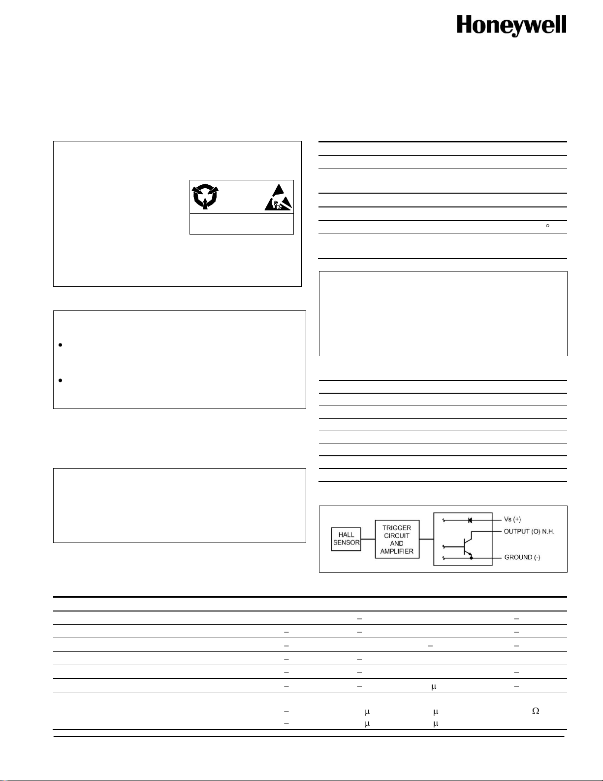
Figure 1. Block Diagram
Use agitated rinse to clean the sensor.
Table 3. Operating Characteristics (over operating voltage and temperature, unless otherwise noted)
Sensing and Control

SS400 Series Temperature Compensated
Digital Hall-Effect Sensor ICs
Table 4. Magnetic Characteristics
Temperature
Operating
Characteristic
Catalog Listing
SS411A
SS411A-L
SS411A-T2
SS411A-T3
SS413A
SS413A-L
SS413A-T2
SS413A-T3
SS441A
SS441A-L
SS441A-T2
SS441A-T3
SS443A
SS443A-L
SS443A-T2
SS443A-T3
SS449A
SS449A-L
SS449A-T2
SS449A-T3
SS461A
SS461A-L
SS461A-T2
SS461A-T3
SS466A
SS466A-L
SS466A-T2
SS466A-T3
Bipolar
Bipolar
Unipolar
Unipolar
Unipolar
Latching
Latching
-40 C
[-40 F]
min. op.
NS
NS
50 G
110 G
285 G
5 G
100 G
max. op.
70 G
140 G
135 G
215 G
435 G
110 G
200 G
min. rel.
-70 G
-140 G
20 G
80 G
210 G
-110 G
-200 G
max. rel.
NS
NS
120 G
190 G
360 G
-5 G
-100 G
min. dif.
15 G
20 G
15 G
25 G
30 G
50 G
200 G
0 C
[32 F]
min. op.
NS
NS
53 G
110 G
305 G
5 G
100 G
max. op
65 G
140 G
117 G
190 G
400 G
90 G
185 G
min. rel.
-65 G
-140 G
20 G
80 G
230 G
-90 G
-185 G
max. rel.
NS
NS
99 G
165 G
325 G
-5 G
-100 G
min. dif.
15 G
20 G
15 G
25 G
30 G
50 G
200 G
25 C
[77 F]
min. op.
NS
NS
55 G
110 G
310 G
10 G
100 G
max. op.
60 G
140 G
115 G
180 G
390 G
85 G
180 G
min. rel.
-60 G
-140 G
20 G
75 G
235 G
-85 G
-180 G
max. rel.
NS
NS
95 G
155 G
31 G5
-10 G
-100 G
min. dif.
15 G
20 G
20 G
25 G
30 G
50 G
200 G
85 C
[185 F]
min. op.
NS
NS
45 G
90 G
290 G
110 G
95 G
max. op.
60 G
140 G
120 G
180 G
400 G
85 G
180 G
min. rel.
-60 G
-140 G
15 G
70 G
215 G
-85 G
-180 G
max. rel.
NS
NS
105 G
165 G
325 G
-10 G
-95 G
min. dif.
12 G
20 G
15 G
15 G
30 G
50 G
190 G
125 C
[257 F]
min. op.
NS
NS
40 G
80 G
270 G
5 G
80 G
max. op.
65 G
140 G
123 G
190 G
410 G
100 G
180 G
min. rel.
-65 G
-140 G
15 G
60 G
200 G
-100 G
-180 G
max. rel.
NS
NS
115 G
180 G
340 G
-5 G
-80 G
min. dif.
12 G
20 G
8 G
10 G
30 G
50 G
160 G
150 C
[302 F]
min. op.
NS
NS
35 G
65 G
260 G
5 G
70 G
max. op
70 G
140 G
125 G
200 G
420 G
110 G
185 G
min. rel.
-70 G
-140 G
10 G
55 G
185 G
-110 G
-185 G
max. rel.
NS
NS
120 G
195 G
345 G
-5 G
-70 G
min. dif.
10 G
20 G
5 G
5 G
30 G
50 G
140 G
NOTICE
Bipolar Hall-effect sensors may have an initial output in either the ON or OFF state if powered up with an applied magnetic field in
the differential zone (applied magnetic field >Brp and <Bop). Honeywell recommends allowing 10 µs for output voltage to stabilize
after supply voltage has reached 5 V.
2 Honeywell Sensing and Control