

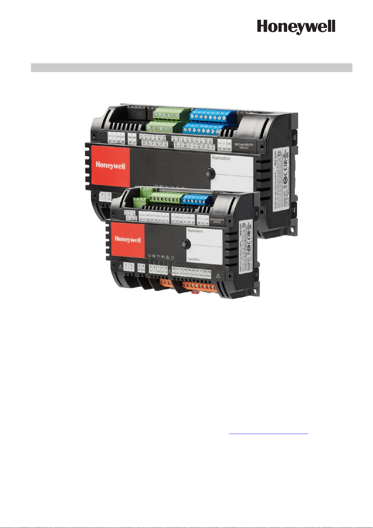
Spyder Model 5
ENGINEERING TOOL
USER GUIDE
® U.S. Registered Trademark
Copyright © 2019 Honeywell Inc. ▪ All Rights Reserved 31-00282-01
IMPORTANT NOTE: Email your Host Id to Honeywell WEBs Customer Care (WEBsLicense@honeywell.com), so we can
move the license to your organization. For additional queries contact to the distributor.

SPYDER MODEL 5 ENGINEERING TOOL - USER GUIDE
31-00282ES-01 2
TABLE OF CONTENTS
TABLE OF CONTENTS .............................................................................................................................................................. 2
ABOUT THIS USER GUIDE ............................................................................................................................................... 4
APPLICABLE TECHNICAL LITERATURE ........................................................................................................................................ 4
SYSTEM REQUIREMENTS ............................................................................................................................................... 4
RESTRICTIONS AND RECOMMENDATIONS .................................................................................................................................. 4
SECURITY BEST PRACTICES ........................................................................................................................................................ 4
Security Check List ............................................................................................................................................................. 5
INTRODUCTION ................................................................................................................................................................. 6
BASIC CONCEPTS ....................................................................................................................................................................... 6
SYSTEM ARCHITECTURE ............................................................................................................................................................. 9
PREREQUISITES .............................................................................................................................................................. 10
ADDING IRM APPLICATION TEMPLATE TO PALETTE ................................................................................................................. 10
SETTING UP CIPER MODEL 50 CONTROLLER ......................................................................................................... 14
Creating CIPer Model 50 Station ................................................................................................................................... 16
Configuring CIPer Model 50 Controller as BACNET IP - MSTP Router ................................................................... 17
ENGINEERING MODES .................................................................................................................................................. 22
OFFLINE ENGINEERING ............................................................................................................................................................ 22
Creating IRM BACnet Device ........................................................................................................................................... 25
Matching Devices.............................................................................................................................................................. 28
ONLINE ENGINEERING ............................................................................................................................................................. 32
SYNCHRONICITY CHECK VIA CONTROL MANAGER .................................................................................................................... 35
FACTORY DEVICE HANDLING .................................................................................................................................................... 37
DETAILED OFFLINE PROCEDURE ............................................................................................................................................. 39
DETAILED ONLINE PROCEDURE ............................................................................................................................................... 43
WORKING WITH APPLICATIONS – THE IRM PROGRAM ......................................................................................... 45
PREPARING NIAGARA WORK ENVIRONMENT ............................................................................................................................ 45
IRM PROGRAM COMPONENTS................................................................................................................................................. 48
The Control Manager Procedure .................................................................................................................................... 50
Periodic Program .............................................................................................................................................................. 53
Event Program ................................................................................................................................................................... 54
Onboard IO ......................................................................................................................................................................... 55
Alarms ................................................................................................................................................................................. 58
APPLICATION ENGINEERING GUIDELINES ................................................................................................................................ 59
Commissioning and Station Copier Usage ................................................................................................................... 59
Final Step after Application Engineering ...................................................................................................................... 59
Memory and Folder Usage .............................................................................................................................................. 59
IRM Function Blocks and External Application Components ................................................................................... 60
Application Templates Usage ......................................................................................................................................... 60
REFERENCE DATAPOINTS USAGE ............................................................................................................................................. 60
Manual Creation and Mapping of Reference Points (A) ............................................................................................. 65
Automatic Creation and Mapping of Reference Points via Drag & drop (B) ........................................................... 76
APPLICATION MANAGEMENT .................................................................................................................................................... 82
Teaching and Learning .................................................................................................................................................... 82
Teaching to Controller ...................................................................................................................................................... 82
Learning from Controller ................................................................................................................................................. 83
Clearing Controller ............................................................................................................................................................ 85
Clearing Project ................................................................................................................................................................. 85
Checking Hardware Compatibility.................................................................................................................................. 86

SPYDER MODEL 5 ENGINEERING TOOL – USER GUIDE
3 31-00282ES-01
Taking Snapshot ................................................................................................................................................................ 88
Restoring Snapshot .......................................................................................................................................................... 89
Swapping IRM Program ................................................................................................................................................... 90
MASTER SYNC .......................................................................................................................................................................... 93
Cloning Application ........................................................................................................................................................... 94
Applying Master Sync ....................................................................................................................................................... 95
Excluding Function Block Items from Master Sync .................................................................................................... 97
SPLITTING-OFF APPLICATION .................................................................................................................................................. 99
CONTROLLER MAC ADDRESS ASSIGNMENT .......................................................................................................................... 102
Setting MAC Address of Controller ............................................................................................................................... 104
SYNCHRONIZING DEVICE TIME ............................................................................................................................................... 106
FIRMWARE DOWLOAD ................................................................................................................................................ 107
ALARMING ...................................................................................................................................................................... 108
MISCELLANEOUS ......................................................................................................................................................... 108
VALUE UPDATES AFTER DEVICE POWER FAILURE .................................................................................................................. 108
HIDING SLOTS ........................................................................................................................................................................ 108
SYLK WALL MODULE USAGE .................................................................................................................................................. 110

SPYDER MODEL 5 ENGINEERING TOOL – USER GUIDE
31-00282ES-01 4
ABOUT THIS USER GUIDE
This user guide describes the configuration and management of Spyder Model 5 controllers connected to a BACnet
MSTP network via a CIPer Model 50 controller. Configuration and Management is done by using the Spyder Model 5
Engineering Tool based on the Honeywell WEBStation.
Applicable Technical Literature
• Spyder Model 5 Product Data: 31-00280ES-01
• Spyder Model 5 Installation Guide: 31-00281ES
• IRM-NX FUNCTION BLOCKS User Guide: EN2B-0415GE51
• IRM-NX APPLICATION Guide: EN2B-0416GE51
• Honeywell General Security Best Practices – System Engineering Guide: 31-00129
• CIPer Model 30 Hardening Guide: 31-00207EFS
• CIPer Model 50 Product Datasheet: 31-00197
• CIPer Model 50 Installation & Commissioning Instructions: 31-00233EFS
• CIPer Model 50 Mounting Instructions: 31-00234EFS
• CIPer Model 50 Controller User Guide: 31-00198
SYSTEM REQUIREMENTS
Niagara : Honeywell WEBStation N4.4.94.xx and higher
Firmware : IRMN4-IMG_V0.0.7.1.bin
Tools : Spyder5_Tool_1.0.0.37
DemoApplication : IRMN_H_0001_Ver_1.0.1.5
Firmware and Software Downloads : The firmware and the software can be downloaded from The Honeywell
Buildings Forum
Restrictions and Recommendations
For successful and seamless engineering, it is recommended to note the following internal system restrictions:
Number of BACnet Devices : max. 64 devices per channel. Depending on performance needs of
the application and bus traffic it is recommended to keep the number
of devices below 64.
Controller Memory Usage : max. 80 % (recommended 70 %)
Function Blocks Usage : - max. 32 IRM folders overall
- max. 100 function blocks per folder
- max. 2000 function blocks overall
- max 1 wall module per device
Baud rate : 9600 through max. 76800 (default = 38400)
Security Best Practices
This section provides the necessary information about the requirements for configuring and managing the security
when installing and maintaining a product or system.
Honeywell hereby expressly states that its controllers are not inherently protected against cyber-attacks from the
Internet and that they are therefore intended solely for use in private networks. However, even private networks can
still be subject to malicious cyber-attacks by skilled and equipped IT individuals and thus require protection.
Customers should therefore adopt the installation and security best practices guidelines for Honeywell BACnet
MS/TP-based products to mitigate the risk posed by such attacks.

SPYDER MODEL 5 ENGINEERING TOOL – USER GUIDE
5 31-00282ES-01
The following check list describe the General Security Best Practices for Honeywell BACnet MS/TP-based products. They
are listed in order of increasing mitigation. The exact requirements of each site should be assessed on a case-by-case
basis. The vast majority of installations implementing all of the mitigation levels described here will be far in excess of
that required for satisfactory system security.
Incorporating the security check list items 1-5 will generally meet the requirements for most automation control network
installations.
Additional information can be obtained from:
• Honeywell General Security Best Practices – System Engineering Guide (31-00129)
• CIPer Model 30 Hardening Guide (31-00207-01)
Security Check List
1. Use the latest version of IRM software including firmware and software modules.
2. Include the WEBStation N4.x installation files, configuration files (including station backup), certificates and
licenses in the disaster recovery plan.
3. Make sure that the PC running WEBStation N4.x, where possible, is secured against unauthorized physical access.
4. Make sure that the local ethernet network that the PC is connected to is secured, e.g. by the use of firewalls and
intrusion detection systems.
5. The PC is running the latest version of the Windows operating system, with all updates and service packs.
6. The PC is running virus protection software.
7. Appropriate user accounts are set up on PC and access to files is restricted to only those who are authorized.
8. WEBStation N4.x is configured to use HTTPS using a certificate from a trusted Certificate Authority.
9. WEBStation N4.x users are configured as required.
10. WEBStation N4.x is configured to backup data regularly to a secure location as per your company's backup policy.
11. Ensure that complete commissioning is carried out in a closed local area network without connecting to the internet
to avoid unauthorized sniffing of BACnet message packets.

SPYDER MODEL 5 ENGINEERING TOOL – USER GUIDE
31-00282ES-01 6
INTRODUCTION
The Spyder Model 5 Engineering Tool provides the following functions:
• Setting up the IRM and CIPer Model 50 controllers for usage in a BACnet MSTP system architecture
• Creating BACnet devices offline and online
• Creating applications for IRM controllers
• Synchronizing applications between project and controllers
• Adjusting terminal layout deviations (hardware compatibility)
• Creating Master Sync groups
• Splitting applications
• Cloning applications
• Firmware download
• Alarming
• Printout
Basic Concepts
Engineering Modes
There are two kinds of engineering you can use for engineering an IRM project:
• Offline Engineering
In this mode, you create an empty BACnet device manually, add an application (optional) and match it afterwards to
a device discovered on the bus by using the service pin. This is normally applied when doing the engineering in the
office without having the hardware available but knowing the hardware specification of the devices to be used later
at the plant.
• Online Engineering
In this mode, you discover the devices on the BACnet network in the first step and use the devices instantly for
application engineering. This is recommended when doing the engineering directly at the plant with the devices
already installed on the BACnet bus.
Synchronization Status of Application
The current content of the applications engineered in the project and running in the connected IRM controller is
permanently monitored by the control manager (Online engineering only). Modifications can be any of the following:
• Control strategy icons (function blocks)
• Links between function blocks
• Notes
• Annotations
• Author
• Description
• Terminals
• Notification classes
• Etc.
Modifications can be detected in the controller, or in the project, or in both.
They can be synchronized by applying the following actions:
• Teach to controller
• Learn from controller
• Clear project (as required)
• Clear controller (as required)
Teaching and Learning
Synchronization of the application in the project and controller application can be performed in two ways:
• Teaching to Controller
Downloads the application in the project to the controller
• Learning from Controller
Uploads the application from the controller in the project

SPYDER MODEL 5 ENGINEERING TOOL – USER GUIDE
7 31-00282ES-01
Teaching Modes
Any modifications in either the project or the controller can be synchronized in one of the following modes:
• on-demand will be performed explicitly as desired by the user
• immediate occurs instantly when the change is done
Clearing Controller / Project
The application in the project and in the controller, can be cleared independently.
IRM Program
The IRM program includes the control manager, the control strategy (periodic and event programs), the hardware
configuration (on board I/O) and the alarming.
Control Manager
The control manager takes care of the major control functions and displays the current status of the IRM program
accordingly. The following information is provided:
• Author of the application
• Description
• Application type
• Function block family, version, and numbers
• Number of folders and links
• Memory usage
• Hardware features and compatibility
• Controller connection type
• Engineering units (measurement) type
• Drop of BACnet point settings
• Communication status
• Synchronization status
• Last program change and commissioning dates
Periodic program
Includes the control strategy running in a cyclic manner on a fixed time base
Event program
Includes event-driven control strategy triggered by particular IO changes
On board I/O
Shows the hardware I/Os of the controller
Alarms
Provides the notification classes for establishing alarming
Hardware Compatibility Check
The hardware configurations of the used physical controller and the hardware defined for the controller in the
application can be checked. Any differences are indicated graphically on the terminals on the wire sheet.
Taking / Restoring Snapshot
The current status of an application can be backed up and restored later. This allows restoring a changed application if
these changes should be discarded.
Swapping IRM Program
Swapping saves RAM space and reduces processor load and bus traffic. The current state of a swapped device is frozen
and saved to an IRM repository on the disk. Then, synchronization is no more possible. In order to synchronize swappedout devices, the devices must be swapped in again. Swapping can be applied to a single or to all devices per step.
Spyder Model 5 Engineering Tool
The Spyder Model 5 Engineering Tool provides the work environment for engineering the controllers.

SPYDER MODEL 5 ENGINEERING TOOL – USER GUIDE
31-00282ES-01 8
IRM Operations Monitor / Jobs Sidebar
The IRM Operations Monitor shows all actions in a popup window and all actions are summarized in a list in the Jobs
window.
IRM Palette
The following palette is available for creating the application:
• honIrmControl - provides control function blocks and templates for IRM BACnet devices, IRM programs, and folders.
• honIrmAppl - provides standard FCU application with all commonly used functionalities.
SPYDER MODEL 5 ENGINEERING TOOL – USER GUIDE
9 31-00282ES-01
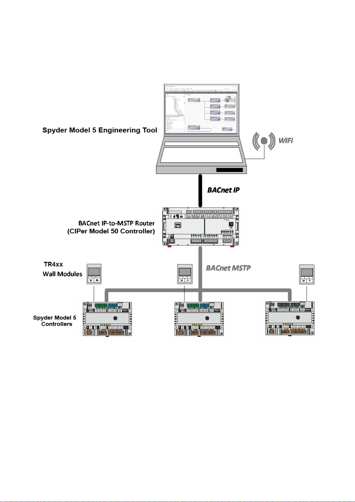
System Architecture
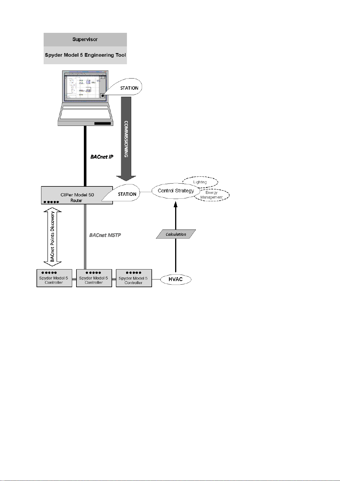
The following schematic shows an example for a BACnet MSTP based system containing a CIPer Model 50 controller as
a router and 3 IRM (Spyder Model 5) controllers for room control. The system is engineered using the Spyder Model 5
Engineering Tool based on the WEBStation N4.4 or higher.
Fig. 1. System Architecture based on Spyder Model 5 Engineering Tool, Spyder Model 5 and CIPer Model 50
Controllers

SPYDER MODEL 5 ENGINEERING TOOL – USER GUIDE
31-00282ES-01 10
PREREQUISITES
It is assumed that you are familiar with basic Niagara techniques and functions, such as creating platforms, stations,
and networks etc.
Make sure that the Spyder Model 5 and CIPer Model 50 controllers are properly connected (see Spyder Model 5
Installation Guide, 31-00281ES and CIPer Model 50 Installation & Commissioning Instructions, 31-00233EFS.
Make sure that the following steps were done prior of working with the Spyder Model 5 Engineering Tool.
If not already available in the current WEBs N4 installation, copy the following files to the Modules folder:
• honIrmAppl-rt.jar
• honIrmAppl-rt.jar.sig
• honIrmConfig-rt.jar
• honIrmConfig-rt.jar.sig
• honIrmConfig-wb.jar
• honIrmConfig-wb.jar.sig
• honIrmControl-rt.jar
• honIrmControl-rt.jar.sig
Adding IRM Application Template to Palette
Procedure
1. Make sure that the ´honIrmAppl.jar` file is installed in the Modules folder of the Spyder Model 5 Engineering Tool
installation.
2. Open the Spyder Model 5 Engineering Tool.
SPYDER MODEL 5 ENGINEERING TOOL – USER GUIDE
11 31-00282ES-01
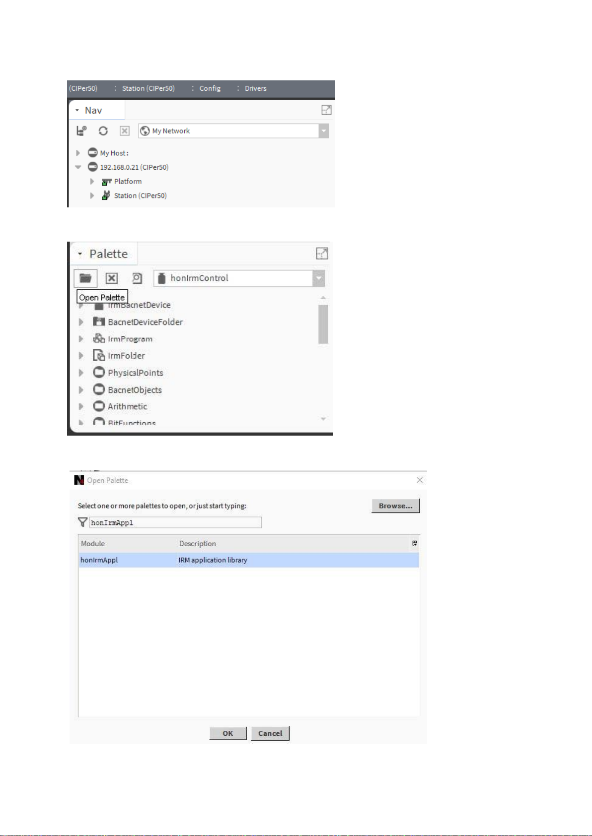
3. On the platform and connect to the station.
4. On the Palette pane, click Open Palette icon.
5. In the Open Palette dialog box, enter ´honIrmAppl.jar`.
SPYDER MODEL 5 ENGINEERING TOOL – USER GUIDE
31-00282ES-01 12
6. If not already selected in the list, select ´honIrmAppl.jar`, and then click OK.
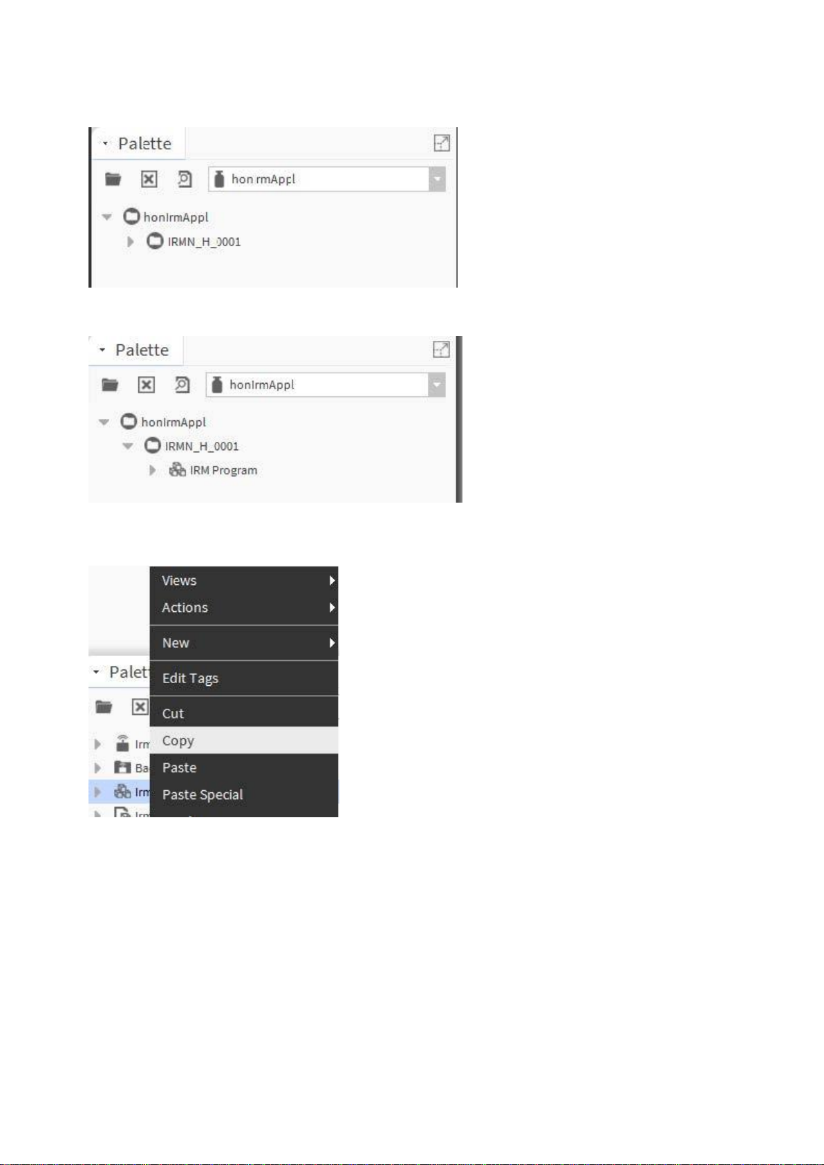
7. In the Palette pane, expand the honIrmAppl folder.
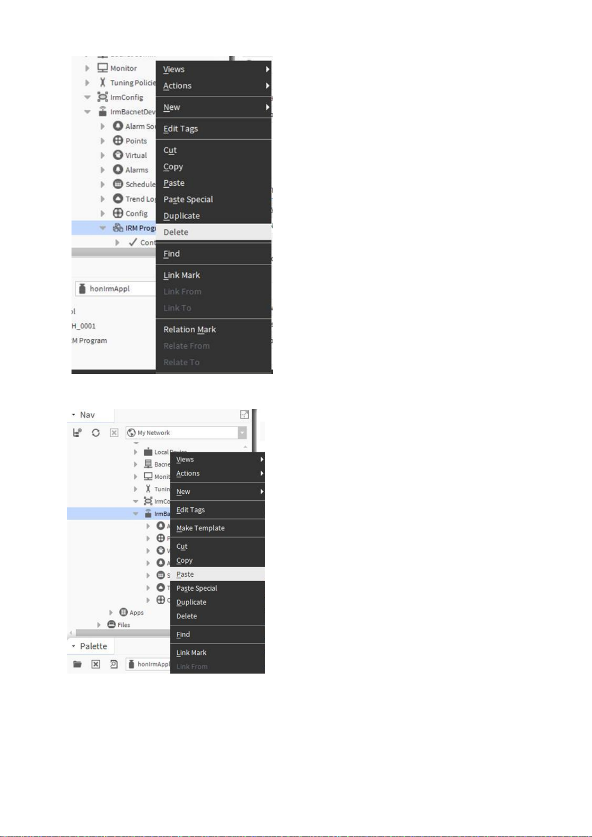
8. Right-click IRM Program and click Copy in the context menu.
9. In the Nav tree, expand the IRM device and delete the existing IRM Program.
SPYDER MODEL 5 ENGINEERING TOOL – USER GUIDE
13 31-00282ES-01
10. Right-click the IRM device and click Paste in the context menu.

SPYDER MODEL 5 ENGINEERING TOOL – USER GUIDE
31-00282ES-01 14
SETTING UP CIPer Model 50 CONTROLLER
In order to access the IRM controllers via Spyder Model 5 Engineering Tool or supervisor, a BACNET IP - MSTP router
must be implemented. For this purpose, it is recommended to use the CIPer Model 50 NX controller which it can host
and run a station for IRM engineering in parallel.
NOTE: The CIPer Model 50 controller can also be used as a router. But it can only be used as a router since it cannot
host a station for IRM engineering.
The CIPer Model 50 controller is setup using standard Niagara techniques and functions such as creating platforms,
stations, and networks. Hence, only the specialties for the CIPer Model 5, steps 2 and 5 are described in the following.
NOTE: For detailed information on standard Niagara techniques and functions, please refer to the Niagara online
documentation and/or the CIPer Model 50 Controller User Guide: 31-00198-01.
Setting up the CIPer Model 50 controller as router and host for an IRM station (optional), includes the following main
steps:
Offline Engineering
1. Open platform (PC)
2. Create CIPer Model 50 station
3. Start and connect to CIPer Model 50 station
4. Create BACnet Network
5. Configure CIPer Model 50 as BACNET IP - MSTP Router
Online Engineering
1. Commission Controller
(see figure next page).
For detailed information on offline and online engineering, please refer to the “Engineering modes” section, pg. 22.
SPYDER MODEL 5 ENGINEERING TOOL – USER GUIDE
15 31-00282ES-01
Fig. 2. Basic Engineering for Typical CIPer Model 50 and Spyder Model 5 Application Scenario
SPYDER MODEL 5 ENGINEERING TOOL – USER GUIDE
31-00282ES-01 16
Creating CIPer Model 50 Station
For detailed information on standard Niagara techniques and functions, please refer to the Niagara online
documentation and/or the CIPer Model 50 Controller User Guide: 31-00198-01.
Procedure
1. Open the platform on the PC.
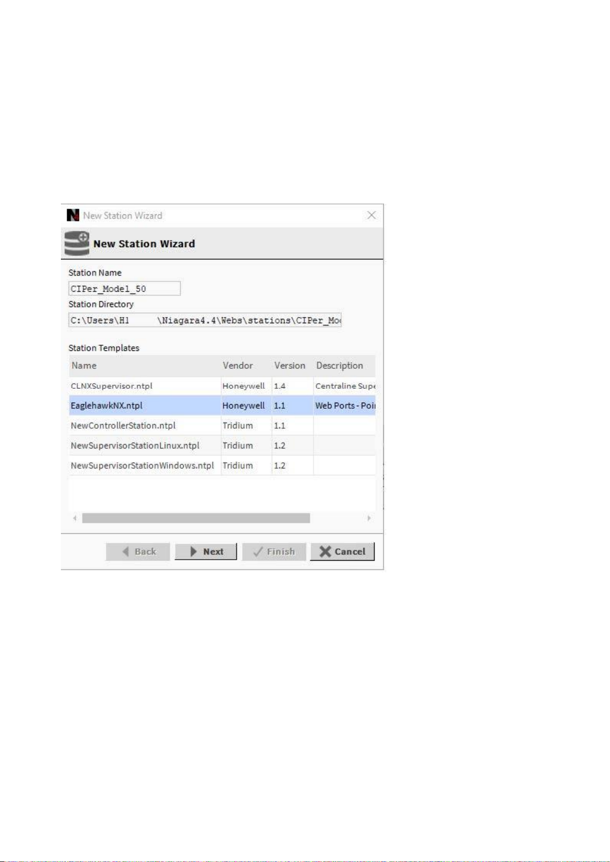
2. Start creating the station using the New Station Wizard.
3. In the New Station Wizard dialog, select the ´EaglehawkNX.ntpl` template.
4. Continue with creating the station (standard Niagara procedure).
SPYDER MODEL 5 ENGINEERING TOOL – USER GUIDE
17 31-00282ES-01
Configuring CIPer Model 50 Controller as BACNET IP - MSTP Router
In order to access the Spyder model 5 controllers via Spyder Model 5 Engineering Tool or supervisor, a BACnet IP –
MSTP router must be implemented. For this, it is recommended to use the CIPer Model 50 controller which can host and
run a station for Spyder Model 5 engineering in parallel.
NOTE: For detailed information on standard Niagara techniques and functions, please refer to the Niagara online
documentation and/or the CIPer Model 50 Controller User Guide: 31-00198-01.
Prerequisite Steps
1. Open the platform (PC).
2. Create CIPer Model 50 station
3. Start and connect to CIPer Model 50 station
Procedure
1. Create BACnet Network
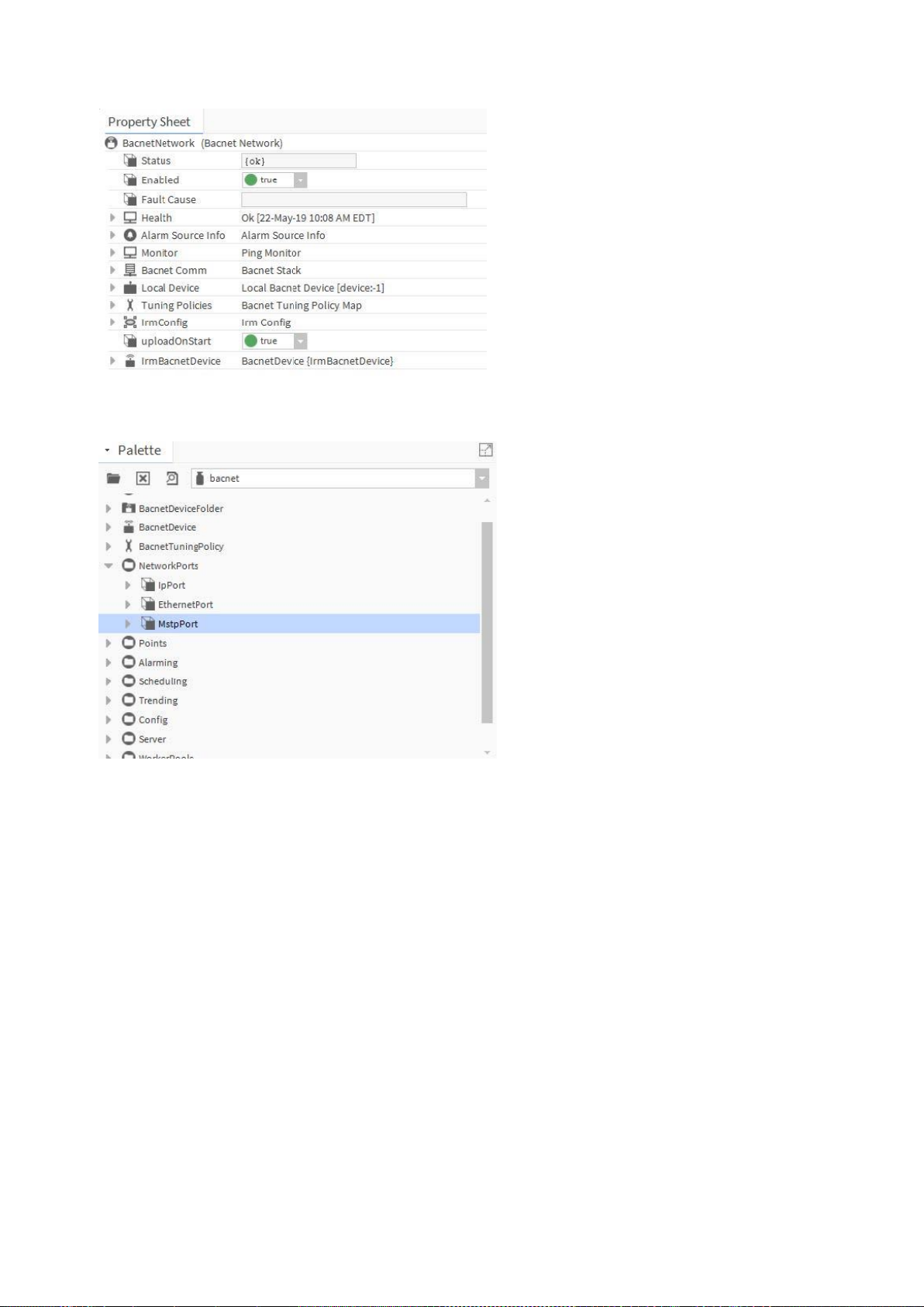
2. Select the Property Sheet of the BACnet network.
SPYDER MODEL 5 ENGINEERING TOOL – USER GUIDE
31-00282ES-01 18
3. Open the BACnet palette and expand NetworkPorts.
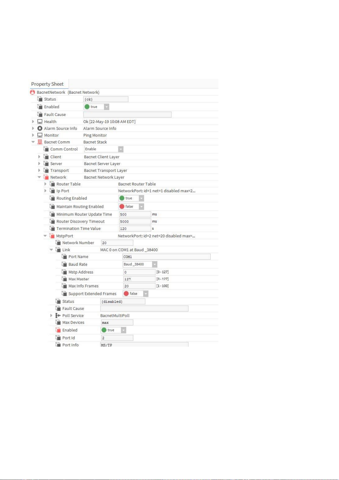
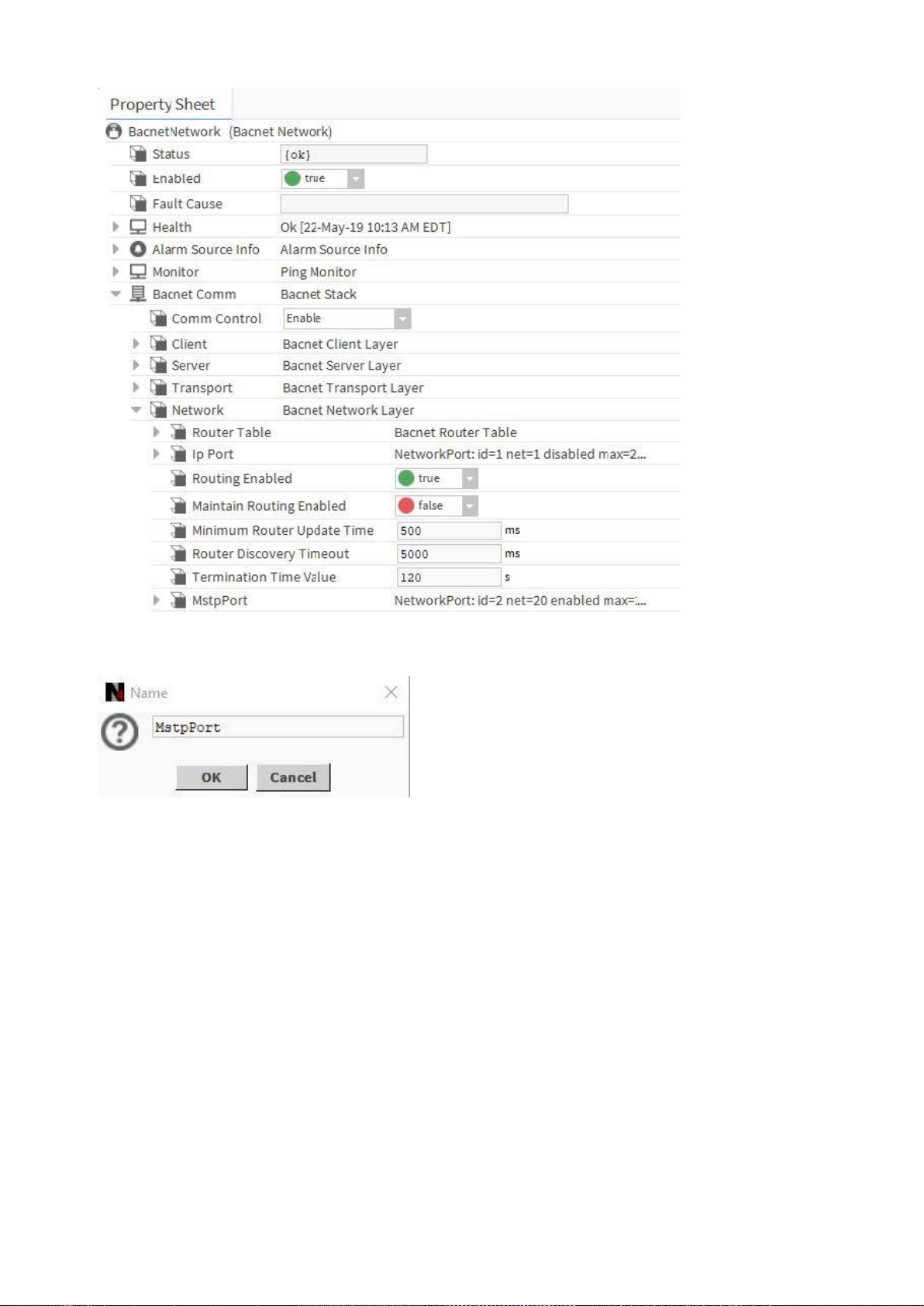
4. Expand BACnet Comm and Network on the Property Sheet
SPYDER MODEL 5 ENGINEERING TOOL – USER GUIDE
19 31-00282ES-01
5. From the BACnet palette, add the MstpPort to Network.
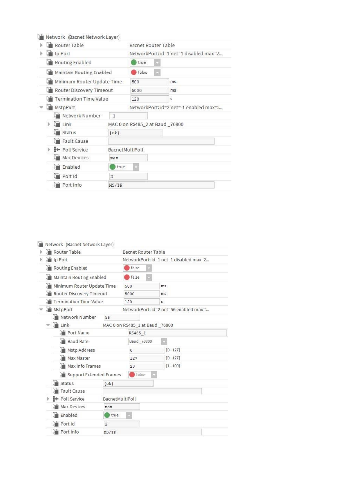
6. Expand MstpPort and Link.
SPYDER MODEL 5 ENGINEERING TOOL – USER GUIDE
31-00282ES-01 20
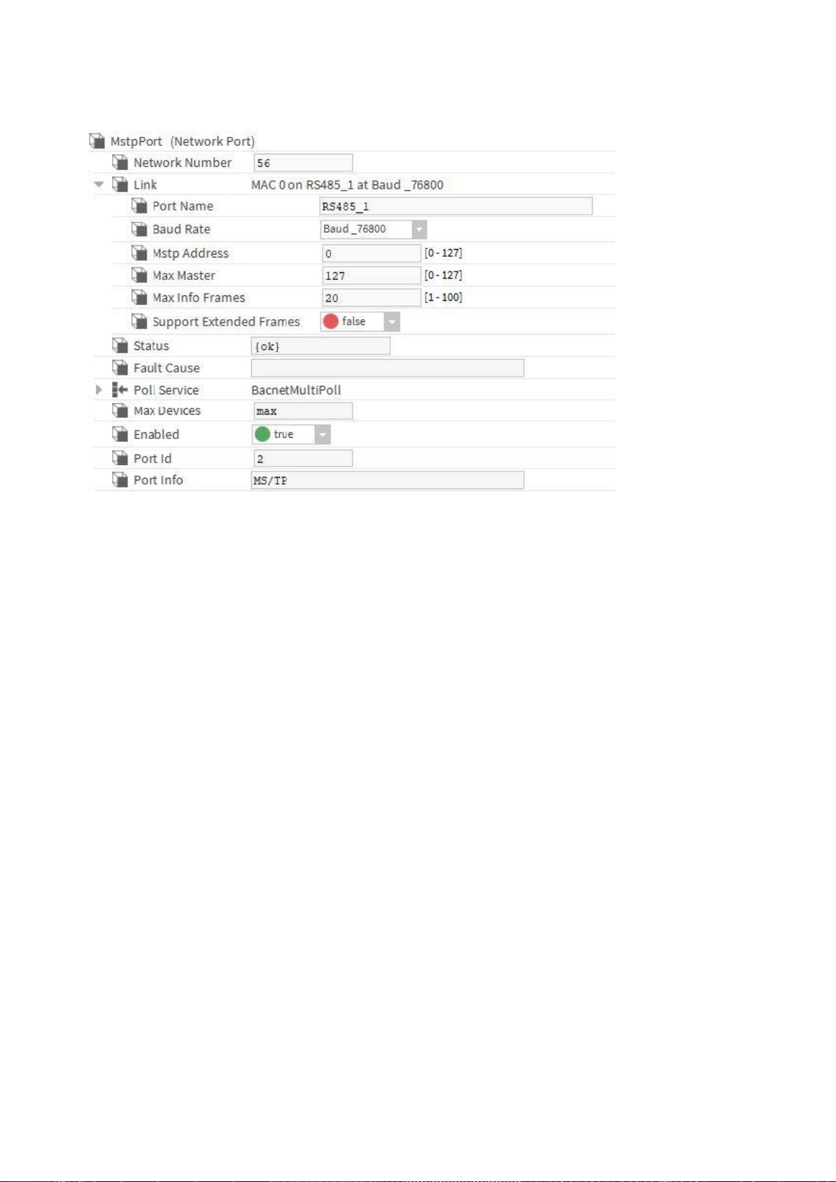
7. Set/enter the following:
• Network Number = any, e.g. 56 (must be less or equal than 65535)
• Port Name = RS485_1
• Baud Rate = Baud_38400 (see also “Baud rate note” below)
• Enabled = true
SPYDER MODEL 5 ENGINEERING TOOL – USER GUIDE
21 31-00282ES-01
8. Click Save.
NOTE: If any of the configuration settings are changed during operation, you must restart the CIPer Model 50
controller (see also Baud rate Note).
9. Commission the CIPer Model 50 station to the CIPer Model 50 controller (standard Niagara procedure).
NOTE: For detailed information on standard Niagara techniques and functions, please refer to the Niagara online
documentation and/or the CIPer Model 50 Controller User Guide: 31-00198-01.
Baud rate Note
The following baud rates for the MSTP interface in the Spyder Model 5 controller are supported:
• 9600
• 19200
• 38400 (default)
• 57600
• 76800
The baud rate of each Spyder Model 5 controller on the BACnet MSTP bus is automatically set by the defined baud rate
of the BACnet IP - MSTP Router (CIPer Model 5) controller after the Spyder Model 5 controller is powered up and
connected to the BACnet MSTP bus.
Setting/changing the baud rate of a single Spyder Model 5 controller is not possible.
When changing the baud rate of the BACnet MSTP bus of a running system, any connected Spyder Model 5 controller
must be power-cycled to adapt the changed baud rate.

SPYDER MODEL 5 ENGINEERING TOOL – USER GUIDE
31-00282ES-01 22
ENGINEERING MODES
There are two kinds of engineering you can use for engineering an Spyder Model 5 project:
• Offline Engineering
In this mode, you create an empty BACnet device manually, add an application and match it afterwards to a device
discovered on the BACnet bus by using the service pin. This is normally applied when doing the engineering in the
office without having the hardware available but knowing the hardware specification of the devices to be used later
at the plant.
• Online Engineering
In this mode, you discover the devices on the BACnet network in the first step and use the devices instantly for
application engineering. This is recommended when doing the engineering directly at the site with the devices
already installed on the BACnet bus.
Offline Engineering
Offline engineering includes the following steps:
• Create IrmBacnetDevice
• Create application for the IrmBacnetDevice (optional)
• Later at the site, do the following:
o Connect to the BACnet network
o Discover devices on the BACnet network
o Match the empty device with a discovered device
o Synchronize the application, if necessary, by applying any of the following actions appropriately:
- Learn from controller
- Teach to controller
- Clear project
- Clear controller
For detailed descriptions, please refer to the corresponding sections:
• Creating IRM BACnet Device, p. 25
• Working with Applications – The IRM Program, p. 45
•

SPYDER MODEL 5 ENGINEERING TOOL – USER GUIDE
23 31-00282ES-01
Matching Devices , p. 28
• Teaching to Controller, p. 82
• Learning from Controller, p. 83
• Clearing Project, p. 85
•

SPYDER MODEL 5 ENGINEERING TOOL – USER GUIDE
31-00282ES-01 24
Clearing Controller, p. 85
• Checking Hardware Compatibility, p. 86.
For further information on offline engineering, please refer also to the “Factory Device Handling“ section, p. 37.

SPYDER MODEL 5 ENGINEERING TOOL – USER GUIDE
25 31-00282ES-01
Creating IRM BACnet Device
Procedure
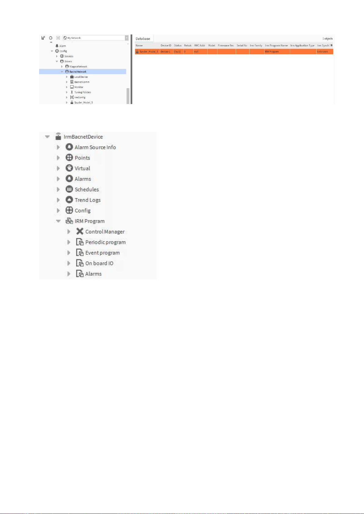
1. Double-click the BACnet network folder in the Nav tree, and then select Irm Bacnet Device Manager view.
2. On the bottom, click New.
3. In the New dialog box, select ´Irm Bacnet Device`, and then click OK.
RESULT: The Irm Bacnet Device is created and added to the Database pane and the BacnetNetwork tree.
SPYDER MODEL 5 ENGINEERING TOOL – USER GUIDE
31-00282ES-01 26
4. Expand the device and create the IRM program by adding control strategy, hardware layout and alarm settings
optional).
• To do so, please refer to the section “Working with Applications – The IRM Program“, p. 45.
5. After finishing the application engineering, match the offline disconnected device to the desired physical device
discovered on the BACnet network (see “

SPYDER MODEL 5 ENGINEERING TOOL – USER GUIDE
27 31-00282ES-01
Matching Devices “, p. 28).
6. Teach the application to the controller. If there is an application already running in the controller, clear the controller
7. Finally perform the hardware compatibility check to make sure that the application is properly designed for running
seamlessly in the created device.
8. If software recommends, remove function blocks in the control logic.
NOTE: Add the physical IO points. Make sure to select the right physical point template that matches the online
device model.
NOTE: It is allowed matching smaller offline device models with bigger online device models. It is strongly
recommended not match devices vice versa, since hardware compatibility issues may arise. In this case, please
execute the hardware compatibility check and rework the application accordingly. Or, install a bigger device with
more hardware I/Os at the site.
For further information on offline engineering, please refer also to the “Factory Device Handling” section, p. 37.
SPYDER MODEL 5 ENGINEERING TOOL – USER GUIDE
31-00282ES-01 28
Matching Devices
Purpose
This function matches an offline-configured, disconnected IRM device to an online discovered IRM controller on the
BACnet network.
The offline-configured, disconnected IRM device will be configured according to the properties of the online discovered
IRM device.
Inconsistencies may occur and can be solved by using the corresponding actions to establish synchronicity.
Procedure
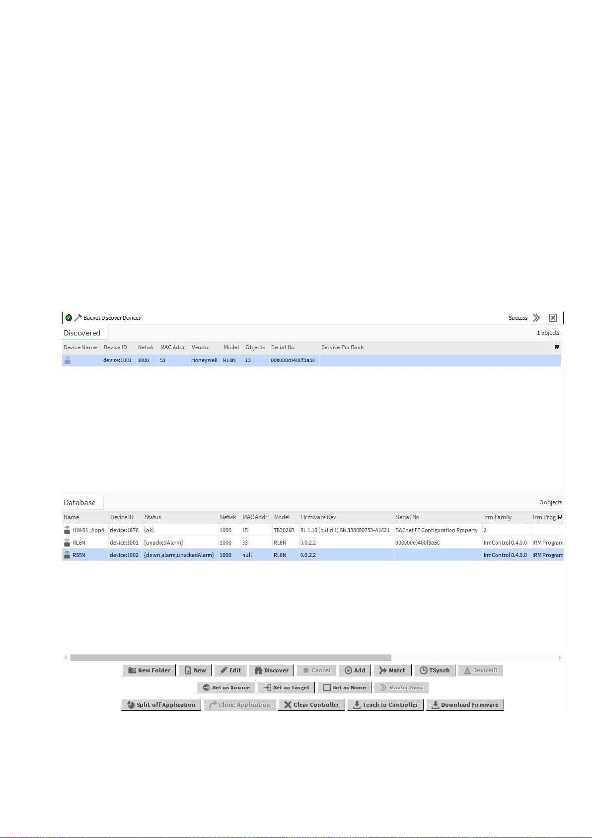
1. Press the service pin at the device you want to match to the offline created IRM BACnet device. Do this for all devices,
you want to match.
2. On the Discovered pane, click Discover.
RESULT: All devices available in the BACnet network are discovered.
RESULT: In the Service Pin Rank column, the service pin action is indicated by consecutive numbers depending on
the time when the service pin was pressed at the device.
3. On the Discovered pane, select the online device and in the Database pane, select the offline created IRM BACnet
device.
4. At the bottom, click Match.
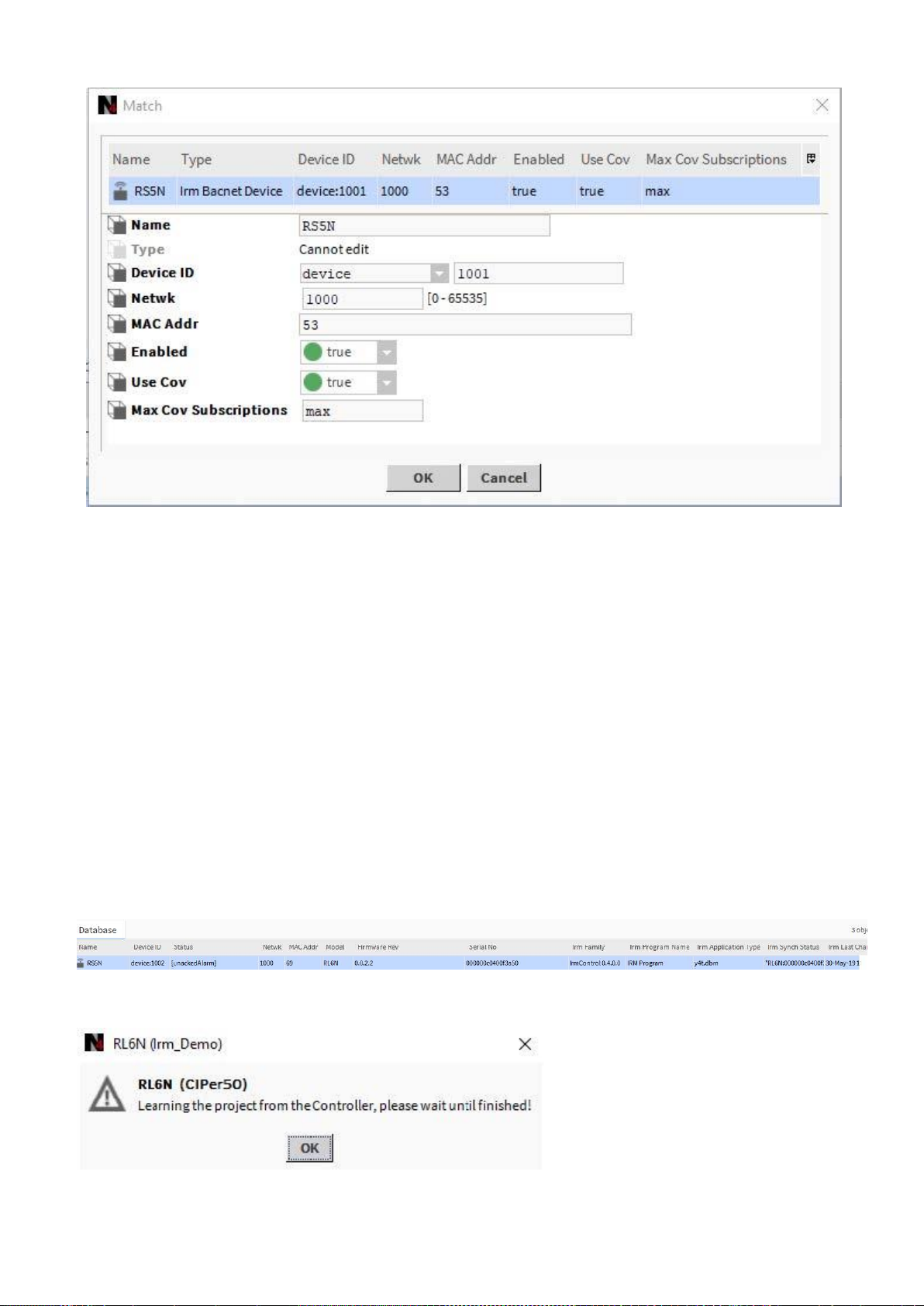
RESULT: The Match dialog box displays.
SPYDER MODEL 5 ENGINEERING TOOL – USER GUIDE
29 31-00282ES-01
5. If desired, you can enter the device ID, Network address, and MAC Address.
6. Enable Use Cov by selecting ´true` from the drop-down List box.
7. Click OK.
RESULT: The devices are matched as the properties of the disconnected offline IRM BACnet device indicate in the
Database pane. The device gets the data of:
• Device ID
• Status
e.g. Alarm, unacknowledged alarm.
• Model
• Firmware Revision
• Serial No.
• Irm Family
• Irm Program Name
• Irm Application Type
• Irm Sync Status
synchronized or not synchronized
• Irm Last Change
• Irm Master Sync
The Irm Sync Status shows whether the device is part of a master sync group (source, target, none)
The application status is checked by learning the project from the controller as displayed in the following message:

SPYDER MODEL 5 ENGINEERING TOOL – USER GUIDE
31-00282ES-01 30
8. Click OK.
RESULT: If as a result, any inconsistencies of the application appear between the disconnected IRM BACnet device
and the discovered Spyder Model 5 controller, a notification message will be displayed and the relevant
synchronization status is indicated in the control manager (see section “Synchronicity Check via Control Manager”, p.
35).
9. To solve any inconsistencies, synchronize the applications by doing any of the following:
• Clear project
• Clear controller
• Teach to controller
• Learn from controller
• Checking Hardware Compatibility
For detailed descriptions, please refer to the corresponding sections:
• Clearing Project, p. 85
•
 Loading...