

Pneumatic Switches
C4857
FRONT VIEW
SP970A 3-1/2 (89)
SP970C 3-7/8 (98)
SIDE VIEW
0
80
60
40
20
100
2-1/2
(63)
1-1/2
(38)
7/8
(22)
2-1/4
(57)
1-7/8
(48)
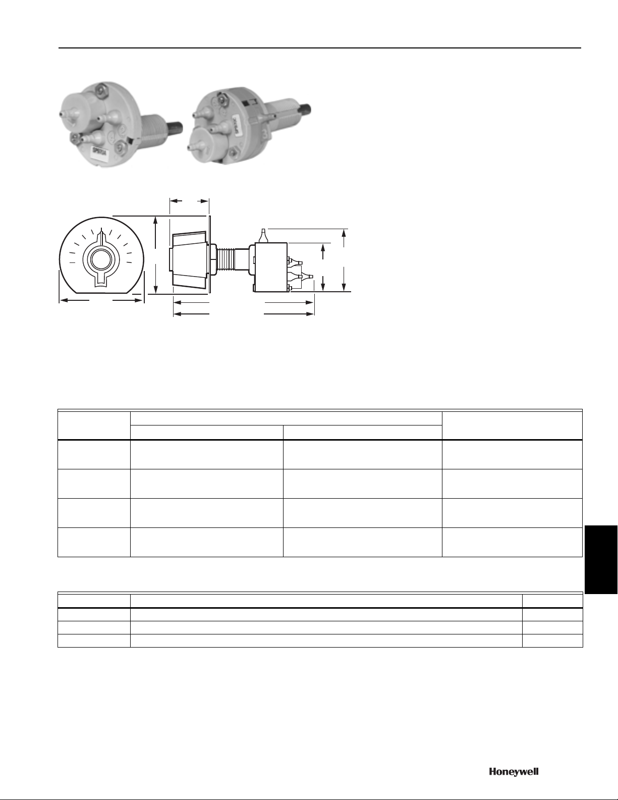
SP970 Pneumatic Manual or Minimum Position Switches
Used to manually position a remote damper actuator or to reset the
setpoint of a pneumatic controller. They can also provide minimum
damper position by setting a minimum pressure limit in the branch
line to the damper actuator. Replacement kits are available for
Johnson, Powers, Robertshaw, Barber-Colman, and older
Honeywell switches.
• Two spans available as shipped. Six spans with breakaway stops on
knob.
• Pilot bleed and isolated pilot models available.
• Wall or panel mounting.
Dimensions in inches (millimeters)
Air Connections: Barb fitting for 5/32 in. (4 mm) O.D. plastic tubing
Airflow Usage: 0.022 scfm (9.8 mL/s)
Capacity: 0.021 scfm (9.4 mL/s) below minimum position. Above
minimum position, device feeding pilot determines capacity
Operating Humidity Range: 5 to 95% RH
Temperature Range: 0 F to 140 F (-18 C to +60 C)
Maximum Safe Operating Pressure: 30 psi (207 kPa)
Switch Operation: Used to manually position a remote damper
actuator or reset setpoint of pneumatic controller
Switch Type: Three-port pneumatic manual or minimum position switch
Mounting: Panel or Wall
Comments: The setpoint knob normally rotates 188 degrees. Two
breakaway stops on the knob allow rotation of 244 degrees and 300
degrees.
Pneumatic
Output Span
Product Number
SP970A1005/U 10 psi (with 188 degree knob rotation)
SP970A1013/U 5 psi (with 188 degree knob rotation)
SP970C1001/U 10 psi (with 188 degree knob rotation)
SP970C1043/U 5 psi (with 188 degree knob rotation)
16 psi (with 300 degree knob rotation)
13 psi (with 244 degree knob rotation)
8 psi (with 300 degree knob rotation)
6.5 psi (with 244 degree knob rotation)
16 psi (with 300 degree knob rotation)
13 psi (with 244 degree knob rotation)
8 psi (with 300 degree knob rotation)
6.5 psi (with 244 degree knob rotation)
69 kPa (with 188 degree knob rotation)
110 kPa (with 300 degree knob rotation)
90 kPa (with 244 degree knob rotation)
34 kPa (with 188 degree knob rotation)
56 kPa (with 300 degree knob rotation)
45 kPa (with 244 degree knob rotation)
69 kPa (with 188 degree knob rotation)
110 kPa (with 300 degree knob rotation)
90 kPa (with 244 degree knob rotation)
34 kPa (with 188 degree knob rotation)
56 kPa (with 300 degree knob rotation)
45 kPa (with 244 degree knob rotation)
Includes(psi) (kPa)
Knob, 0 to 100% scale plate and locknuts
Knob, 0 to 100% scale plate and locknuts
Knob, 0 to 100% scale plate and locknuts
Knob, 0 to 100% scale plate and locknuts
Controls
Pneumatic Switch Replacement Parts
Product Number Description Used With
14003022-003/U Final Assembly, manual and minimum position switch, 10 psi span SP970A
14003199-002/U Bag assembly with two scale plates, knob assembly and nuts for SP470A SP470A
176112023 Pneumatic 2-Position Switch SP470A
70-6910 693
Pneumatic Switches
2
PILOT
SP970 SP970A
1
BRANCH
MA N
4
C4298A
2
P LOT
1
BRANCH
MAIN
4
3
2
PILOT
SP970C
A. BUILDING TO MINIMUM SETTING
B. BALANCED AT MINIMUM SETTING
D. BALANCED AGAINST PILOT
1
BRANCH
MAIN
DISC
VENT
4
C4300A
PILOT
CHAMBER
3
2
PILOT
SP970C
1
BRANCH
MAINVENT
4
3
2
PILOT
SP970C
1
BRANCH
MAINVENT
4
3
2
PILOT
SP970C
C. PILOT BUILDING BRANCH ABOVE
MINIMUM SETTING
1
BRANCH
MAINVENT
4
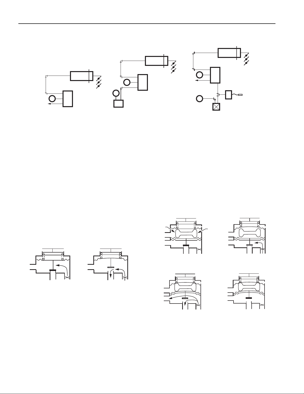
SP970 Operation
SP970 Typical Piping
DAMPER
ACTUATOR
BRANCH
EXH
A. MANUAL POSITION APPLICATION
2
M
1
4
SP970A
DAMPER
BRANCH
M
M
1
2
CONTROLLER
B. MINIMUM POSITION APPLICATION WITH
CONTROLLER INPUT
ACTUATOR
2
1
4
SP970A
DAMPER
BRANCH
M
EXH
SP970C
M
C. MINIMUM POSITION APPLICATION WITH
BLEED TYPE THERMOSTAT INPUT (LP916)
ACTUATOR
2
1
3
4
THERMOSTAT
INSERTION
C4471A
Operation
SP970A Three Port Switches
PRESSURE REGULATOR OPERATION
Main line air flows through the restriction into the branchline
chamber and out the nozzle. Branchline pressure increases
until it is strong enough to compress the spring and lift the
diaphragm off the nozzle. Air flow out the nozzle is controlled by
the balance between the branchline pressure and spring force.
See Typical Piping Diagram A Above.
MINIMUM POSITION OPERATION
See Typical Piping Diagram B above. An external signal is
connected to Port 4 (Exhaust Port). When the external signal is
greater than the spring load, the nozzle opens and branchline
pressure is the same as the external signal. When the external
signal is less than the spring load, branchline pressure is
controlled as described above. See Operation Diagram below.
SP970A Operation
SP970C Four Port Switches
These minimum position devices have a separate dead-ended
chamber connected to Port 3 to receive an external signal.
When the external signal is less than the spring load, the signal
has no effect and functions similar to the SP970A as a pressure
regulator. When the external signal is greater than the spring
load, the spring load is isolated and the device duplicates the
input signal. See Operation Diagram below.
Piping Diagram C above shows a typical four-port SP970C
application. The minimum-position switch keeps the pneumatic
actuator at a minimum position until the thermostat pressure is
greater than the minimum position valves. The thermostat then
controls the actuator.
SP970C Operation
694 customer.honeywell.com 70-6910
 Loading...