

Solid State Economizer System
W7212/13/14
C7400
M7215
C7150
C7046
C7232B
C7632A
C7660
(CONSISTING OF: C7046C DISCHARGE AIR SENSOR OR C7150B MIXED AIR SENSOR, C7232 OR C7632 CARBON DIOXIDE SENSOR, C7400 SOLID STATE ENTHALPY SENSOR OR C7660 SOLID STATE TEMPERATURE SENSOR, M7215
DAMPER ACTUATOR AND W7212, W7213 OR W7214 SOLID STATE ECONOMIZER LOGIC MODULE)
SYSTEM ENGINEERING GUIDE
FEATURES
C7046C Discharge Air Sensors have probe lengths of 8 in.
(203 mm) and nominal sensor resistance of 3000 ohms at
77°F (25°C).
• No setting or calibration required.
• Solid state components not affected by dust or dirt.
• Fast reacting.
• Rugged aluminum insertion probe.
C7150B Mixed Air Sensor is used with the M7215 Damper
Actuator to sense mixed or discharged air in rooftop packaged
air conditioning equipment.
• No setting or calibration required.
APPLICATION
The Solid State Economizer System provides an economical
method of providing cooling air by incorporating outdoor air in
the first stage of cooling in heating, ventilating and air
conditioning (HVAC) systems. The Solid State Economizer
System consists of the C7046 Discharge Air Sensor, C7150
Mixed Air Sensor, C7232 or C7632 Demand Control
Ventilation (DCV) Sensor, C7400 Enthalpy Sensor or C7660
Dry Bulb Temperature Sensor, M7215 Damper Actuator, and
W7212 Solid State Economizer Logic Module.
C7232 and C7632 DCV Sensors are stand-alone carbon dioxide (CO
with heating ventilation and air conditioning (HVAC) controllers. They measure the CO
space or duct. They are used in HVAC systems to control the
amount of fresh outdoor air supplied to maintain acceptable
levels of CO
• C7232 models available with LCD that provides sensor
• Non-Dispersion-Infrared (NDIR) technology used to
• Gold-plated sensor provides long-term calibration
• Device provides voltage output based on CO
• C7232 models available with SPST relay output.
• Used for CO
• Automatic Background Calibration (ABC) algorithm
• C7632 has fixed 0 to 10 Vdc from 0 to 2000 ppm. No
) sensors for use in determining ventilation necessity
2
concentration in the ventilated
2
in the space.
2
readings and status information.
measure carbon dioxide gas.
stability.
levels.
2
based ventilation control.
2
based on long-term evaluation reduces required
typical zero-drift check maintenance.
adjustments are necessary.
(Continued)
63-2576—02

SOLID STATE ECONOMIZER SYSTEM
CAUTION
C7400 Solid State Enthalpy Sensor and C7660 Solid State
Temperature Sensors are used with the W7212 Solid State
Economizer Logic Module to allow using outdoor air as the
first stage of cooling in HVAC systems.
• C7400 senses and combines temperature and
humidity of outdoor air (heat index).
• C7660 senses dry bulb temperature only.
• Long-lasting, solid state sensing element is accurate
and stable over time.
• When enthalpy/temperature of outdoor air increases,
the outdoor air damper closes to a preset minimum
position.
• When enthalpy/temperature of outdoor air is low, the
outdoor air damper opens to reduce the building
cooling load.
• Provides 4 to 20 mA output signal to the Economizer
Logic Modules; setpoint is located on economizer
control.
• Maximum economizer savings is achieved with two
C7400 Enthalpy Sensors connected to one
Economizer Logic Modules for differential enthalpy
changeover control.
M7215 Damper Motors are 25 lb-in. spring return damper
actuators that provide modulating control of economizer systems, ventilation dampers and combustion air dampers used
in residential or commercial HVAC equipment.
• M7215 Damper Motors provide modulating control of
economizer dampers from a 2-10 Vdc controller.
• Quiet, high efficiency drive motor.
• High impact, glass-fiber reinforced plastic case is
rugged, lightweight and corrosion resistant.
• Provides 2-10 Vdc output signal proportional to the
shaft position.
W7212 Economizer Logic Modules are used with C7232
Demand Control Ventilation (DCV) Sensors, and solid state
C7400 Enthalpy Sensors or C7660 Dry Bulb Temperature
Sensors to proportion outdoor and return air dampers for control of free cooling in commercial HVAC equipment.
• Operates from thermostat and DCV sensor to provide a
totally integrated control system.
• Solid state control package provides accurate, reliable
and stable control.
• Mounts on M7215 Motor or duct work.
• Control can be tempered by DCV and fan cycling.
• Used with Honeywell actuators.
• Combines minimum and DCV maximum damper
position potentiometers with compressor staging.
• Relay functions with solid state enthalpy or dry bulb
changeover control.
• Terminals included for switching between Occupied
and Unoccupied operation.
• Terminals included for connecting optional S963B1128
Remote Potentiometer for remote minimum damper
position control.
• LED indicates when free cooling is available.
• LED indicates when module is in DCV mode.
• LED indicates when exhaust fan contact is closed.
• W7213 is used with heat pump B terminal.
• W7214 is used with heat pump O terminal.
IMPORTANT
Specifications given in this publication do not include
normal manufacturing tolerances. Therefore, this unit
may not exactly match the listed specifications. Also,
this product is tested and calibrated under closely
controlled conditions and some minor differences in
performance can be expected if those conditions are
changed.
When Installing this Product...
1. Read these instructions carefully. Failure to follow
them could damage the product or cause a hazardous
condition.
2. Check the ratings given in the instructions and on the
product to make sure the product is suitable for your
application.
3. Installer must be a trained, experienced service
technician.
4. After installation is complete, check out product
operation as provided in these instructions.
Electrical Shock or Equipment Damage Hazard.
Can shock individuals or short equipment
circuitry.
Disconnect power supply before installation.
IMPORTANT
All wiring must agree with applicable codes,
ordinances and regulations.
63-2576—02 2
C7046C DISCHARGE AIR SENSORS
)
D
)
02
(25)
)
)
)
)
)
)8 (
)
GASKET
R
)
USH
)
C
BUS
G
SENSO
OBE
GE
)
S
(
)
O
E
SYSTEM
COMPO
S
CO
W
O
W
S
(
)
3
SENSO
E
SYS
UM
GE
S
Y
CONDU
OX
CO
OR
CONDUIT
E
(
)
SYS
COMPO
S
CO
S
(
)
P
)
SOLID STATE ECONOMIZER SYSTEM
Specifications
Intended for use as a discharge sensor in rooftop applications.
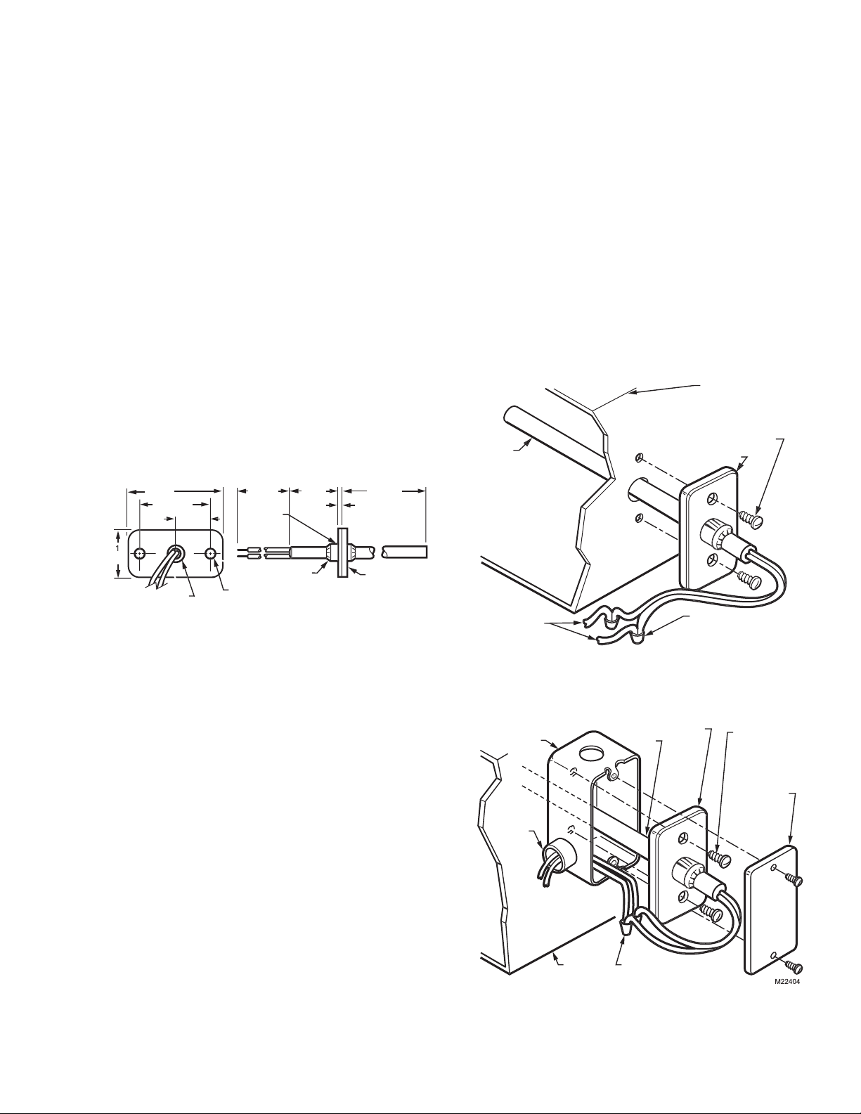
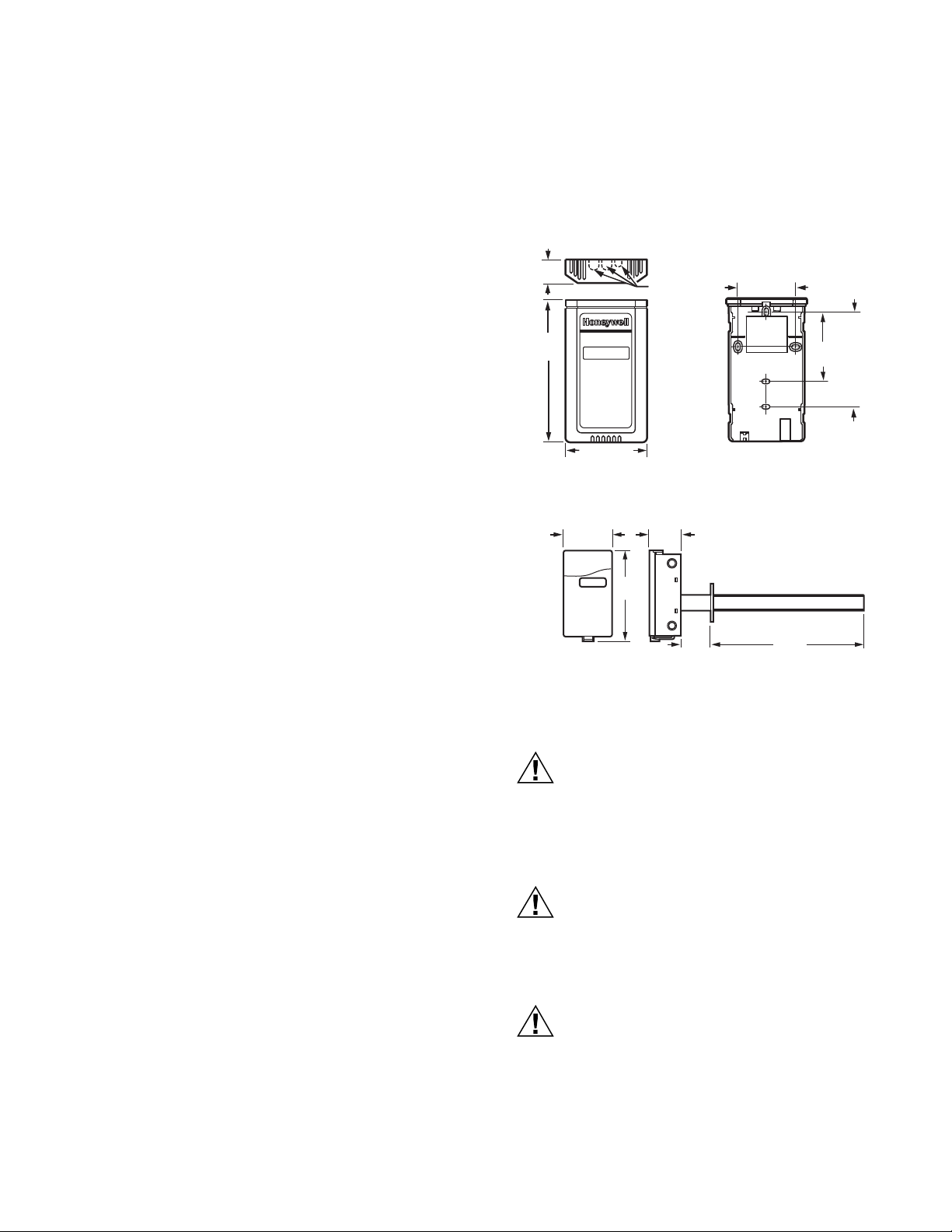
Dimensions: See Fig. 1.
Mounting: Mounting flange requiring two No. 8 screws.
Sensing Element: Carbon type, thermistor-resistor element.
Maximum Ambient Temperature: 250°F (121°C).
Operating Temperature Range: 40 to 150°F (4 to 66°C).
Wiring Connections: 6 in. (152 mm) leadwires.
Performance Characteristics:
Reaction Time Constant with Air Approach Velocity of
500 ft/min (2 m/sec): 60 seconds.
Resistance/Temperature (NTC):
Nominal Resistance: 3000 ohms at 77°F (25°C).
Nominal Sensitivity: 70 ohms per degree F (124 ohms per
degree C) at midrange.
2 (51
1-1/2 (38
3/4 (19
203
PLASTI
HIN
1 (25
6 (152
1/16 (2
4. Fasten the sensor to the duct or plenum surface
with two No. 8 sheet metal screws (not provided).
Mounting in a Junction Box (Fig. 3)
1. Cut a 3/8 in. (9.5 mm) hole in the duct or plenum
surface at the desired location.
2. Remove the center rear knockout from the junction box
and insert the sensing probe through the knockout with
the flange flat against the outlet box.
3. Using the flange as a template, mark and drill two holes
in the junction box and the duct or plenum surface for
No. 8 mounting screws.
4. Insert sensor probe through both the junction box
knockout and the 3/8 in. (9.5 mm) hole drilled in the duct
or plenum and fasten the junction box and sensor to the
duct or plenum surface.
SYSTEM DUCT
OR PLENUM
NO. 8 (4mm
MOUNTING SCREW
PR
R
NOT PROVIDED
FLAN
5/16 (9) DIAMETE
(BUSHING
LOCKING P
1/4 (6
NUTS (2
IAMETER (2 HOLES
NEOPRENE
M224
Fig. 1. C7046C Air Temperature Sensor dimensions
in in. (mm).
NOTE: Sensor probe diameter is 1/4 in. (6 mm).
Installation
The sensor assembly (see Fig. 1) consists of an aluminum
sensor probe (element housed internally) with attached flange
that can be mounted on a flat duct or plenum surface, or in
a 2 in. by 4 in. (51 by 102 mm) junction box using two No. 8
screws. Connections to the sensor are made through two 6 in.
(152 mm) leadwires.
LOCATION
The sensor should be located in the air duct or plenum where
it will sample an average air temperature. Avoid locations
where air stratification can cause sensing errors.
MOUNTING
Mounting on a Flat Duct or Plenum Surface (Fig. 2)
1. Cut a 3/8 in. (9.5 mm) hole in the duct or plenum
surface at the desired location.
2. Insert sensor probe into the duct or plenum until the
flange rests against the duct or plenum wall.
3. If necessary, use the flange as a template to mark
and drill two holes for No. 8 mounting screws.
T
APPROPRIAT
NENT
M2240
Fig. 2. Mounting C7046 Air Temperature
Sensor on a flat duct or plenum surface.
FLAN
TANDARD UTILIT
IT B
NNECT
LOCKNUT
TO APPROPRIATE
TEM
NENT
TEM
DUCT OR
PLEN
R
PROB
NNECT SENSOR WIRE
WITH TWO WIRENUT
CONNECTORS
Fig. 3. Mounting C7046 Air Temperature
Sensor in a junction box.
NNECT SENSOR
IRES WITH TW
IRENUT CONNECTOR
NOT PROVIDED
NO. 8 (4mm)
MOUNTING
SCREWS (NOT
ROVIDED
FACEPLAT
OPTIONAL
NOT PROVIDED
3 63-2576—02
SOLID STATE ECONOMIZER SYSTEM
CAUTION
CAUTION
Wiring
Electrical Shock or Equipment Damage Hazard.
Can shock individuals or short equipment
circuitry.
Disconnect power supply before installation.
Erratic System Operation Hazard.
Failure to follow proper wiring practices can
introduce disruptive electrical interference (noise).
Keep wiring at least one foot away from large inductive
loads such as motors line starters, lighting ballasts,
and large power distribution panels.
Shielded cable is required in installations where these
guidelines cannot be met.
Ground shield only to grounded controller case.
IMPORTANT
1. All wiring must agree with applicable codes,
ordinances and regulations.
2. Do not mount sensor in incorrect environment.
3. Wire according to the applicable controller
instructions.
4. Erratic temperature readings from a sensor can be
caused by improper wiring practices. These must
be avoided to assure proper operation:
•Avoid poor wiring connections.
•Avoid intermittent or missing building earth ground.
•Do not mount sensor in incorrect environment.
Connect low voltage wiring from the sensor to the appropriate
system component terminals using solderless connectors.
See Fig. 3.
Operation
The C7046C Air Temperature Sensors consist of a thermistor
sensing element mounted in a tubular probe. They are applied
at various locations throughout single zone and multizone
duct systems. The negative temperature coefficient (NTC)
characteristic of the thermistor element causes its resistance
to decrease as the sampled air temperature increases. This
resistance shift is balanced with other system sensor signals
by appropriate system logic panels to stabilize system control.
Checkout
Allow the C7046 Air Temperature Sensor to soak in the air
moving through the duct or plenum for a minimum of five
minutes before taking a resistance measurement.
1. Disconnect the sensor leadwires from the associated
system components.
2. Connect an ohmmeter across the leadwires.
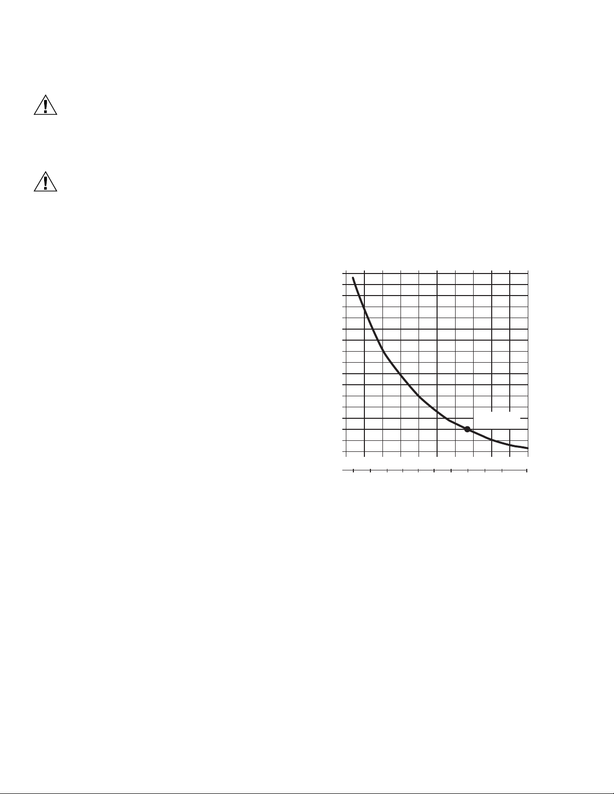
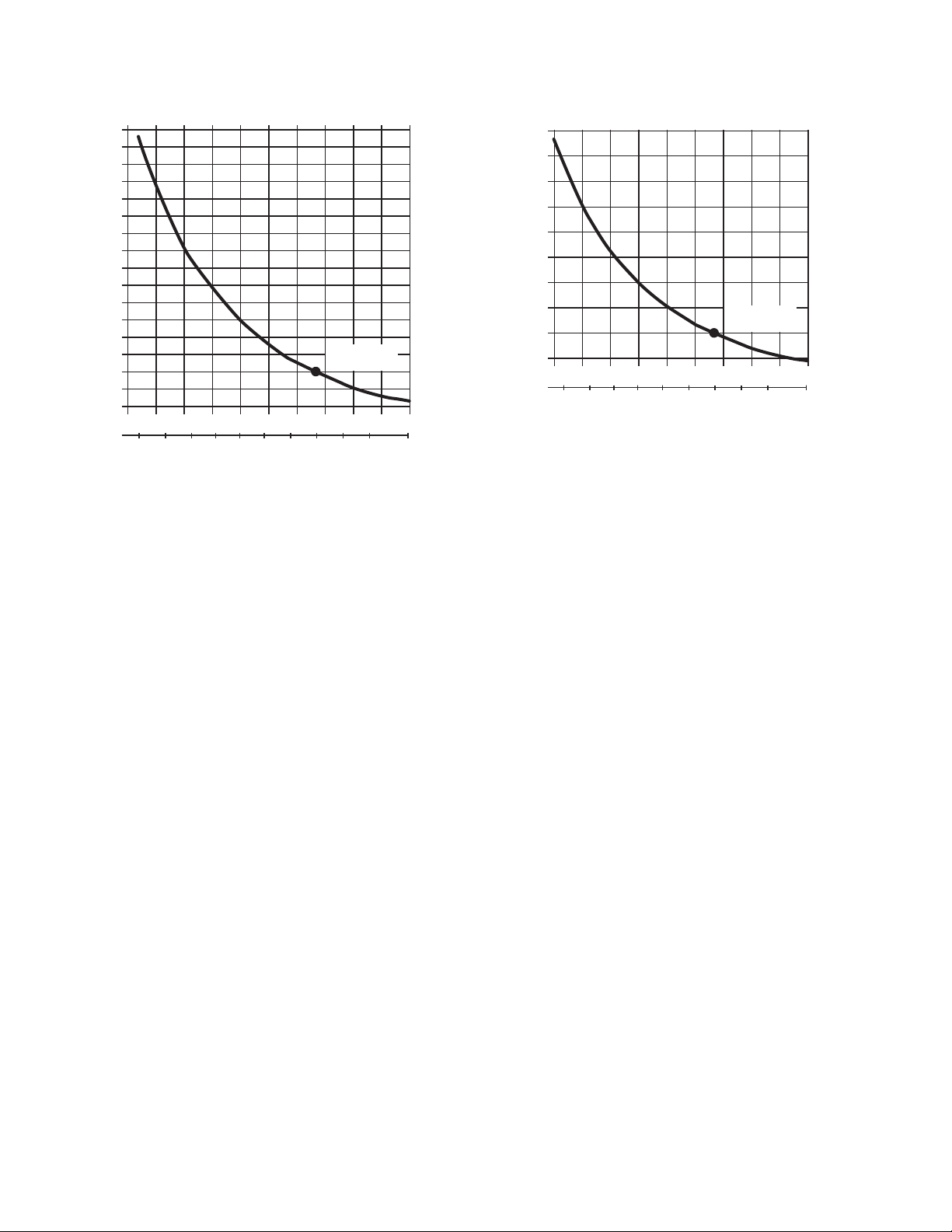
3. Assure nominal resistance measurements are in
accordance with the resistance/temperature curves
shown in Fig. 4.
4. Reconnect sensor leadwires to associated system
components.
5. Check operation of the complete control system.
17000
16000
15000
14000
13000
12000
11000
10000
9000
8000
7000
6000
RESISTANCE (OHMS)
5000
4000
3000
2000
1000
605040 70
0-10
5
TEMPERATURE (DEGREES)
2010
15
Fig. 4. C7046C Sensor resistance vs. temperature.
3,000 OHMS
AT 77 F (25 C)
8010 20 30 90 100
30 35
25-5
F
C
M17969
63-2576—02 4
C7150B MIXED AIR SENSOR
3
R
)
1-1/2
(38)
(51)
3/4
(19)
3/4
(19)
2-3/8
(60)
2-1/4 (57)
M17992
C7150B1004 C7150B1046
SOLID STATE ECONOMIZER SYSTEM
Specifications
Models: See Table 1.
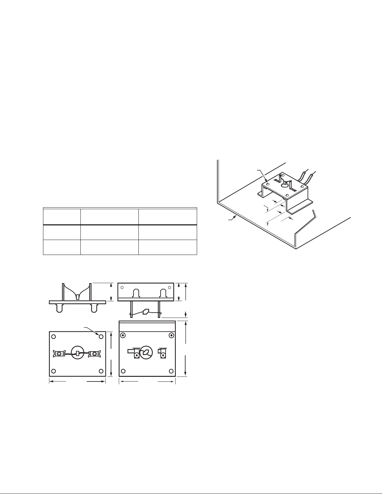
Dimensions: See Fig. 5.
Mounting Arrangement:
Integral mounting flange that requires No. 8 screws.
NOTE: The C7150B1004 requires four No. 8 screws;
the C7150B1046 requires two No. 8 screws.
Ambient Temperature Ratings:
Maximum: 250°F (121°C).
Operating Range: -40 to 110°F (-40 to 43°C).
Shipping Range: -30 to 150°F (-34 to 66°C).
Wiring Connection: 1/4 in. (6 mm) quick-connects.
NOTE: The C7150B1046 includes 4 in. lead wires with
connector for W7340 compatibility.
Table 1. C7150B Models.
Nominal Resistance
Model
at 77°F (25°C)
C7150B1004 3000 ohms 70 ohms per °F
C7150B1046 10K ohms 234 ohms per °F
a
Negative Temperature Coefficient (NTC).
Nominal Sensitivity
at midrange
(124 ohms per °C)
(415 ohms per °C)
Installation
1. Install on a mounting bracket (not included) inside the
2. Wire using 1/4 in. (6 mm) female quick-connect
a
DUCT
mixed air or discharge air duct using No. 8 mounting
screws and nuts. (See Fig. 6).
NOTE: When mounting, ensure that terminals do not
touch metallic conductive surfaces.
terminated wires from C7150B to control inputs.
NOTE: For C7150B1046, splice additional wiring as
needed between sensor and connector.
NO. 8
MOUNTING
SCREW
2 (51)
3/8
(9)
TO APPROPRIATE
SYSTEM SENSOR
1/2 (13)
INPUT
M17938A
Fig. 6. Mounting C7150B [C7150B1004 shown].
/16 (5) DIAMETE
2-1/2 (64
Fig. 5. C7150B approximate dimensions in in. (mm).
NOTE: Fig. 6 displays bracket (not included) and suggested
bracket dimensions in in. (mm).
Operation
The C7150B Air Temperature Sensor consists of a thermistor
sensing element mounted on a phenolic board. It is applied in
ventilation duct systems. The thermistor element negative
temperature coefficient (NTC) characteristic causes its
resistance to decrease as the sampled air temperature
increases. This resistance change is used as a control system
sensor to regulate discharge air temperature in a W973 Single
Zone System or damper position of the M7215A Motor (either
directly, or through the Economizer Logic Module).
Checkout
Allow the C7150B Sensor to soak in the air moving through
the duct for a minimum of 5 minutes before taking a resistance
measurement:
1. Disconnect sensor leadwires from associated system
components.
2. Connect an ohmmeter across the leadwires.
3. Nominal resistance measurements should be in
accordance with the resistance/temperature curves
shown in Fig. 7 and Fig. 8.
4. Reconnect sensor leadwires to associated system
components.
5. Check operation of the M7215A Motor, W973 System,
or the Economizer Logic Module.
5 63-2576—02
SOLID STATE ECONOMIZER SYSTEM
17000
16000
15000
14000
13000
12000
11000
10000
9000
8000
7000
6000
RESISTANCE (OHMS)
5000
4000
3000
2000
1000
605040 70
0-10
5
TEMPERATURE (DEGREES)
15
2010
3,000 OHMS
AT 77 F (25 C)
8010 20 30 90 100
30 35
25-5
F
C
M17969
Fig. 7. C7150B1004 Sensor resistance temperature.
50000
45000
40000
35000
30000
25000
RESISTANCE (OHMS)
20000
15000
10000
5000
605040 70
0
15
5
TEMPERATURE (DEGREES)
2010
10,000 OHMS
AT 77 F (25 C)
8020 30 90 100
30 35
25-5
F
C
M20071
Fig. 8. C7150B1046 Sensor resistance temperature.
63-2576—02 6
C7232 DCV SENSORS
CAUTION
CAUTION
CAUTION
SOLID STATE ECONOMIZER SYSTEM
Specifications
Models: C7232 Sensor and Controller. A stand-alone carbon
dioxide (CO
(one analog and one spst relay).
C7232A: Wall mount model.
C7232B: Duct mount model.
NOTE: Models are available with or without a 4-digit LCD
Dimensions:
C7232A: See Fig. 9.
C7232B: See Fig. 10.
Sensor Performance Ratings:
Response Time: 2 min.
Carbon Dioxide Sensor:
Operation: Non-dispersive infrared (NDIR).
Sampling: Diffusion.
Range: 0 to 2000 ppm ±5% and ±50 ppm.
Annual Drift: 20 ppm (nominal).
Electrical Ratings:
Power Supply: 24 Vac ±20%, 50/60 Hz (Class 2).
Maximum Power Consumption: 3W.
Peak Current (at 20 ms): 600 mA.
Relay:
Configuration: Shipped N.O. (reconfigure with software.)
Contact Rating: 1A at 50 Vac/24 Vdc.
Minimum Permissible Load: 1 mA at 5 Vdc.
Linear Analog Output:
Voltage: 0/2-10 Vdc (resistive load greater than
5000 ohms).
Current: 0/4-20 mA (resistive load less than 500 ohms).
Outputs (Jumper Adjustable, see Table 3):
Analog: 0-10 Vdc (Default: 2-10 Vdc, 500 to 1500 ppm).
Relay: Normally Open Spst (Default: Close at 800 ppm).
) sensor with two jumper-adjustable outputs
2
that indicates the current CO
concentration.
2
Underwriters Laboratories Inc. Listed, File No. E4436.
cUL.
C7232B: Flammability Rating, UL94-5V.
C7232A: NEMA1.
C7232B: NEMA3.
1
(25)
5-1/16
(128)
3-5/32 (80)
KNOCKOUTS
FOR
EUROPEAN
APPLICATIONS
2-3/8 (60)
STANDARD
2-3/8
(60)
MOUNTING
CONDUIT
Fig. 9. C7232A dimensions in in. (mm).
3-5/16 (84)
M17592
5-5/8
(142)
1-13/16
(46)
1-5/8
(41)
8 (203)
Fig. 10. C7232B dimensions in in. (mm).
Installation
UTILITY
BOX
(2X4)
HOLES
M17540
Ambient Ratings:
Temperature:
Operating: +32°F to +122°F (0°C to +50°C).
Storage: -4°F to +158°F (-20°C to +70°C).
Relative Humidity (non-condensing): 0 to 95 percent.
CO
Pressure Dependence: 1.4% change in reading per
2
1 kPa deviation from 100 kPa.
Connections:
Wiring:
C7232A: 20-gauge cable with six 8 in. leadwires.
C7232B: 20-gauge cable with six 6 in. leadwires.
Mounting:
C7232A: Vertical surface with standard single-gang junction
box.
C7232B: Sheet metal duct with a sampling tube.
Automatic Background Calibration (ABC) default: On.
Approvals:
CE.
Health Hazard.
Improper use can create dangerous situations.
Use in application for sensing carbon dioxide only.
For life-safety applications, this device can function
only as a secondary or lesser device.
Electrical Shock or Equipment Damage Hazard.
Can shock individuals or short equipment
circuitry.
Disconnect power supply before installation.
Equipment Damage Hazard.
Electrostatic discharge can short equipment
circuitry.
Ensure that you are properly grounded before
handling the unit.
7 63-2576—02
SOLID STATE ECONOMIZER SYSTEM
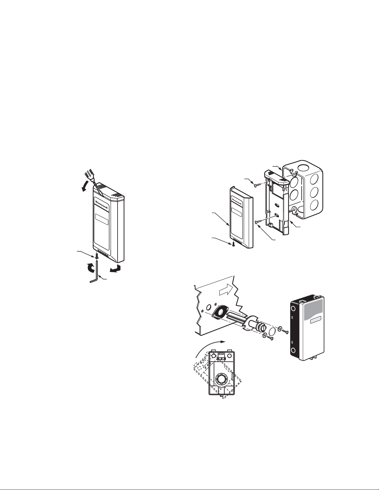
C7232A Cover Removal/Replacement
C7232A COVER REMOVAL (SEE FIG. 11)
1. Remove button head socket cap screw and set it aside.
2. Insert the head of a small screwdriver into the slot at the
center and near the top of the cover.
3. Gently pull the handle down toward the bottom of the
device until a small gap between the subbase and the
cover appears.
4. Remove the screwdriver and pull the cover straight
down until it meets a stop.
5. Pull the cover straight off the subbase.
C7232A COVER REPLACEMENT
1. Feed the wires through the opening in the subbase.
2. Place the cover, with a small gap at the top, flat on top
of the subbase.
3. When the cover rests flat on the subbase, slide it
straight up until it latches in place.
B
NOTE: When mounting on a junction box, see Fig. 12.
3. Replace the cover.
DUCT MOUNTING (SEE FIG. 13)
1. Place gasket on aspiration tube.
IMPORTANT
Ensure largest tab at tube control end is at the top.
2. Insert tube into duct; attach using screws and washers.
IMPORTANT
Leakage into the duct or the C7232 box cover from
the room will skew the sensor readings. Ensure the
box cover and duct seal completely.
3. Place o-ring on tube end; mount the control to the tube.
STANDARD UTILITY CONDUIT BOX
NO. 6 SCREW
FRONT
COVER
BUTTON HEAD
SOCKET CAP
SCREW
A
M17541
C
ALLEN TOOL
Fig. 11. C7232A cover removal.
Location and Mounting
C7232 Sensors mount directly on the wall, sheet metal duct,
or a panel. When planning the installation, allow enough
clearance for maintenance and service. Mount the sensor in a
well-ventilated area.
NOTES: Do not install the sensor where it can be affected by:
WALL MOUNTING
The C7232 Wall Mount models can be mounted using two or
four screws:
— drafts or dead spots behind doors and in corners.
— air from ducts.
1. Remove C7232 cover.
2. Mount the subbase to the wall using washers and two or
four screws (not supplied) appropriate for the wall
material.
BUTTON HEAD
SOCKET CAP
SCREW
NO. 6 SCREW
Fig. 12. Junction box mounting (C7232A).
FLOW
Fig. 13. Duct mounting (C7232B).
SUBBASE
M17542
M17591
63-2576—02 8
SOLID STATE ECONOMIZER SYSTEM
CAUTION
CAUTION
L1
(HOT)
L2
M17543
1
1 POWER SUPPLY. PROVIDE
DISCONNECT MEANS AND
OVERLOAD PROTECTION
AS REQUIRED.
C7232
24V
YELLOW
BLACK
RED
BROWN
ORANGE
GREEN
ANALOG
OUT
+
–
Wiring
The factory ships the device with the output default settings
shown in Table 3 and Table 4. Set the jumpers and wire the
device (see Table 2 and Fig. 14).
Electrical Shock or Equipment Damage Hazard.
Can shock individuals or short equipment
circuitry.
Disconnect power supply before installation.
Equipment Damage Hazard.
Electrostatic Discharge Can Short Equipment
Circuitry.
Ensure that you are properly grounded before
handling the unit.
IMPORTANT
1. All low voltage connections to this device must be
24 Vac Class 2.
2. All wiring must comply with applicable local codes,
ordinances and regulations.
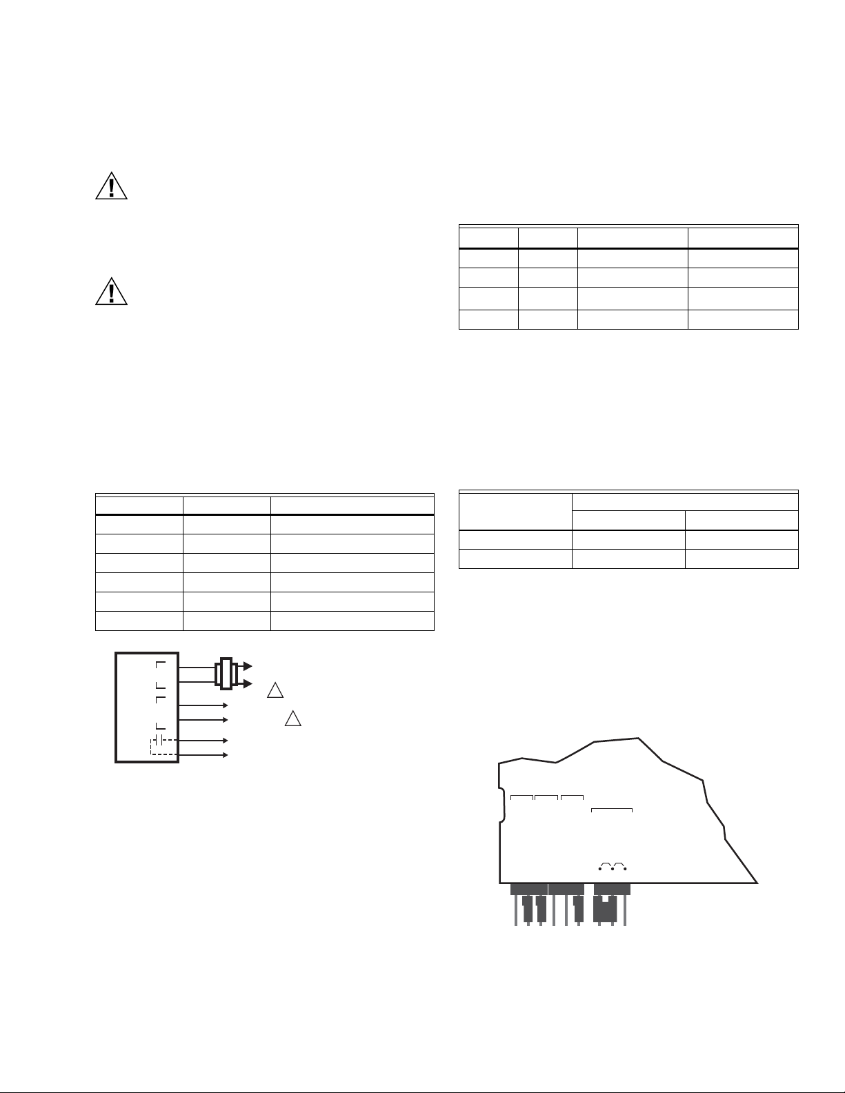
Table 2. C7232 Wiring Connections (see Fig. 14).
Wire Color Designation Function
Red G+ 24 Vac Hot
Black G0 24 Vac Common
Yellow OUT1 Analog Output Signal
Brown M Analog Output Common
Orange NO Relay Output Normally Open
Green COM Relay Output Common
Operation
Input Signal
The C7232 Sensors have an adjustable range. These ranges
are determined by the SW1 and SW2 jumper settings
(see Table 3).
Tab l e 3 . C O
SW1 SW2 AN (ppm) Relaya (ppm)
On On 0 to 1000 1000
On Off 0 to 2000 1200
Off
b
On
b
Off Off 500 to 2000 1200
a
When the level reaches this value, the contacts close;
when the level drops 100 ppm below this value, the contacts open.
b
Setting when shipped from the factory.
Output Signal
The output signal can be adjusted for 0/2-10Vdc or 0/4-20mA
(see Table 4).
Table 4. Output Signal Jumper Settings
AN
Voltage 0-10Vdc 2-10Vdc
Current 0-20 mA 4-20 mA
NOTES:
— On duct models, remove the screw holding the
board in place to view jumper settings on reverse.
(See Fig. 15.)
— The CO
are independent of each other. 0-100% and
20-100% are simply markings for the OUT jumper
settings on the sensor (to differentiate between
the two voltage and the two current ranges) and
do not refer to or alter the ppm range chosen.
Range Jumper Settings
2
500 to 1500 800
OUT
0-100% 20-100%
settings and the output signal settings
2
Fig. 14. Wiring the C7232.
SW2SW1 OUT
ON
OFF
ON
OFF
AN
20 – 100%
0 – 100%
Current
Voltage
M19424
Fig. 15. C7232 default jumper settings.
9 63-2576—02

SOLID STATE ECONOMIZER SYSTEM
Example
For a CO2 setting of 0-2000 ppm and a voltage output of 0-10 Vdc, the output would be as shown in Table 5 (arbitrary points
along the analog curve).
Table 5. 0-10 Vdc Output Example.
CO
Level (ppm)
2
0 200 400 600 800 1000 1200 1400 1600 1800 2000
Voltage Output (Vdc)012345678910
For a CO
along the analog curve).
setting of 0-2000 ppm and a voltage output of 2-10 Vdc, the output would be as shown in Table 6 (arbitrary points
2
Table 6. 2-10 Vdc Output Example.
CO
Level (ppm)
2
0 250 500 750 1000 1250 1500 1750 2000
Voltage Output (Vdc) 2 3 4 5 6 7 8 9 10
Calibration
Typically, calibration is unnecessary. No calibration kits are
available. However, if CO
chamber using a general gas purge device, the sensor can be
rezeroed:
gas can be purged from the sensor
2
Checkout
Perform a quick test of the unit with the unit powered:
1. Stand close to the unit and breathe air into the sensor.
2. Check the CO2 level registered by the controller to
ensure a strong rise.
3. When connected to a damper in a ventilation system,
IMPORTANT
Any CO
zero level resulting in incorrect CO
present during calibration skews the sensor
2
level reports.
2
the controller typically signals an increase in air flow.
1. Once the sensor stabilizes, use a screwdriver to
connect the two MENU soldering pads.
2. The display should indicate CAL.
3. Execute the zero calibration by connecting the two
ENTER soldering pads.
4. The display should return to providing the measured
CO
level.
2
63-2576—02 10

SOLID STATE ECONOMIZER SYSTEM
9096
S
9/16
(14)
)
5/16
(8)
3-5/3
(80)
(70)
)
/32
(6)
C7400A AND C7400C SOLID STATE ENTHALPY SENSORS
Specifications
Dimensions: See Fig. 16.
Output Signal: 4 to 20 mA current signal increases from
4 mA to 20 mA as enthalpy decreases.
Ambient Temperature Ranges:
Operating: 32°F to +125°F (0°C to +52°C).
Shipping: -40°F to +150°F (-40°C to +66°C).
Maximum Power Consumption: 0.50 VA at 24 Vdc.
Supply Voltage: 12 to 40 Vdc.
Electrical Connections:
Two 1/4 in. (6 mm) quick connect terminals.
Approvals:
Underwriters Laboratories Inc. Flammability Rating: UL94-5V.
2
2-3/4
— Use the C7400A sensor with economizer logic
modules with A, B, C, and D set points and use
the C7400C sensor with economizer logic modules with A, B, C, D, and E set points.
Operation
The C7400 Solid State Enthalpy Sensor is used with a solid
state economizer logic module and damper actuator to
proportion an outdoor air damper in a ventilation system.
Each enthalpy control setpoint (A, B, C, and D for C7400A
and A, B, C, D, and E for C7400C) combines temperature and
humidity conditions, resulting in the control curve shown in
Fig. 35. When the enthalpy of the outdoor air is below (left of)
the appropriate curve, the outdoor air damper can proportion
open on a call for cooling. If the outdoor enthalpy rises above
(right of) the control curve, the outdoor air damper closes to
the minimum position.
NOTE: Curves illustrate reset in temperature control point
due to changes in relative humidity.
For differential enthalpy, turn the control setpoint to D for
C7400A and to E for C7400C (fully clockwise ):
— If outdoor air enthalpy is lower than return air enthalpy, the
outdoor air damper proportions open on a call for cooling.
— If outdoor air enthalpy is higher than return air enthalpy, the
outdoor air damper closes to minimum position. Differential
enthalpy control provides energy savings and increased
comfort by using the air with the lowest enthalpy.
— If outdoor air enthalpy and return air enthalpy are equal, the
outdoor air damper proportions open on a call for cooling.
7
1 (25
3-7/8 (96
M
Fig. 16. Approximate dimensions of C7400 Solid State
Enthalpy Sensor in in. (mm).
Installation
Location
IMPORTANT
When selecting the location, make sure the C7400
Solid State Enthalpy Sensor is not exposed to rain,
snow or direct sunlight.
NOTES:
— The C7400 Sensor can be mounted in any
position. However, the sensor must be installed
where it is exposed to freely circulating air, but
protected from rain, snow and direct sunlight.
— Differential enthalpy control requires two C7400
Sensors. Mount one sensor in the outdoor intake
duct, the other in the return air duct.
— The C7400 Sensor is designed to operate in
500 ft/min. minimum airflow.
NOTE: The relationship between the C7400A Sensor output
current and relative humidity is shown in Fig. 17.
100
90
80
70
60
50
PERCENT RF
40
30
20
10
40
(4)
C7400A OUTPUT CURRENT
20 mA
1
18 mA
50
(10)
60
(16)
TEMPERATURE F ( C)
12 mA
6 mA
14 mA
70
(21)80(27)
10 mA
8
mA
6
mA
4 mA
90
(32)
100
(38)
M22117
Fig. 17. C7400A Sensor output current vs. RH.
11 63-2576—02

SOLID STATE ECONOMIZER SYSTEM
10
20
30
40
50
60
70
80
90
100
40
(4)
50
(10)
TEMPERATURE ºF ( ºC)
M27816
C7400C SENSOR OUTPUT CURRENT
PERCENT RF
60
(16)70(21)80(27)90(32)
100
(38)
20 mA
18 mA
16 mA
14 mA
12 mA
10 mA
8 mA
6 mA
4 mA
NOTE: The relationship between the C7400C Sensor output
current and relative humidity is shown in Fig. 18.
Fig. 18. C7400C Sensor output vs. RH.
63-2576—02 12

C7632A DCV SENSORS
CAUTION
CAUTION
CAUTION
Specifications
Models: C7632 Sensor and Controller. A stand-alone carbon
dioxide (CO
C7632A: Wall mount model.
C7632B: Duct mount model.
Dimensions:
C7632A: See Fig. 9.
C7632B: See Fig. 10.
) sensor with one 0-10 Vdc analog output.
2
4-1/8
(104)
3-3/8
(86)
SOLID STATE ECONOMIZER SYSTEM
Ambient Ratings:
Temperature:
Operating: +32°F to +122°F (0°C to +50°C).
Storage: -4°F to +158°F (-20°C to +70°C).
Relative Humidity (non-condensing): 0 to 95 percent.
Automatic Background Calibration (ABC) default: On.
Electrical Ratings:
Power Supply: 24 Vac ±20%, 50/60 Hz (Class 2).
Maximum Power Consumption:
Average: 1W.
Peak: 2W.
Peak Current (at 20 ms): 300 mA.
Linear Analog Output: 0-10 Vdc.
Mounting:
C7632A: Vertical surface with standard single-gang junction
box.
C7632B: Sheet metal duct with a sampling tube.
CO
Pressure Dependence: 1.6% change in reading per
2
1 kPa deviation from 100 kPa.
Output: Analog: 0-10 Vdc, 0-2000 ppm (fixed).
Sensor Performance Ratings:
Response Time: 2 min.
Carbon Dioxide Sensor:
Operation: Non-dispersive infrared (NDIR).
Sampling: Diffusion.
Range: 0 to 2000 ppm (fixed).
Annual Drift: ±10 ppm (nominal).
Accuracy: ±(30 ppm+2%) at normal temperature/pressure.
Wiring Connections:
C7632A: Terminal block.
C7632B: 20-gauge cable with three 6 in. leadwires.
2-11/16 (68)
Fig. 19. C7632A dimensions in in. (mm).
3-5/16 (84)
5-5/8
(142)
1-13/16
(46)
1-5/8
(41)
8 (203)
Fig. 20. C7632B dimensions in in. (mm).
Installation
Health Hazard.
Improper use can create dangerous situations.
Use in application for sensing carbon dioxide only.
For life-safety applications, this device can function
only as a secondary or lesser device.
Electrical Shock or Equipment Damage Hazard.
Can shock individuals or short equipment
circuitry.
Disconnect power supply before installation.
1-1/16
(27)3-7/8 (99)
M19794
M19795
Approvals:
CE.
Underwriters Laboratories Inc. Listed, File No. E4436.
cUL.
C7632B: Flammability Rating, UL94-5V.
C7632A: NEMA1.
C7632B: NEMA3.
Equipment Damage Hazard.
Electrostatic discharge can short equipment
circuitry.
Ensure that you are properly grounded before
handling the unit.
13 63-2576—02

SOLID STATE ECONOMIZER SYSTEM
M19796
C7632A Cover Removal/Replacement
The cover of the C7632A is fixed by a latch on the underside
of the unit.
C7632A COVER REMOVAL (SEE FIG. 11)
1. Unless the device is mounted, hold the base using the
wiring hole and/or the perforated vent.
2. Depress the tab on the underside of the device.
3. Swing the cover away from the base.
4. Lift cover from base.
C7632A COVER REPLACEMENT
1. Place top cover tab over the ridge along the base top.
2. Swing the cover down.
3. Press the lower edge of the case to latch.
Location and Mounting
C7632 Sensors mount directly on the wall, sheet metal duct,
or a panel. When planning the installation, allow enough
clearance for maintenance and service. Mount the sensor in a
well-ventilated area.
NOTES: Do not install the sensor where it can be affected by:
— drafts or dead spots behind doors and in corners.
— air from ducts.
4. Mount the subbase and wallplate to the junction box
using the lower screw.
5. Replace the cover.
DUCT MOUNTING (SEE FIG. 13)
1. Place gasket on aspiration tube.
IMPORTANT
Ensure largest tab at tube control end is at the top.
2. Insert tube into duct; attach using screws and washers.
IMPORTANT
Leakage into the duct or the C7632 box cover from
the room will skew the sensor readings. Ensure the
box cover and duct seal completely.
3. Place o-ring on tube end; mount the control to the tube.
Fig. 21. C7632A cover removal.
WALL MOUNTING (C7632A)
Mount the C7632A to the wall as follows:
1. Remove the C7632 cover.
2. Mount the device in a vertical position.
3. Mount the subbase directly on a wall using the type of
screws (not supplied) appropriate for the wall material.
4. Replace the cover.
JUNCTION BOX MOUNTING (FIG. 12)
Mount the C7632A to a junction box as follows:
1. Attach the wallplate using only the top screw.
2. Remove the C7632 cover.
3. Place the subbase on the wallplate hook.
M19797
Fig. 22. Junction box mounting (C7632A).
FLOW
M19798
Fig. 23. Duct mounting (C7632B).
63-2576—02 14

SOLID STATE ECONOMIZER SYSTEM
CAUTION
CAUTION
Wiring (Fig. 14)
Electrical Shock or Equipment Damage Hazard.
Can shock individuals or short equipment
circuitry.
Disconnect power supply before installation.
Equipment Damage Hazard.
Electrostatic Discharge Can Short Equipment
Circuitry.
Ensure that you are properly grounded before
handling the unit.
IMPORTANT
1. All low voltage connections to this device must be
24 Vac Class 2.
2. All wiring must comply with applicable local codes,
ordinances and regulations.
Table 7. C7632 Wiring Connections (see Fig. 14).
Designation C7632B Wire Color Function
G+ Red 24 Vac
G0 Black Common
CO
2
C7632
G0 CO
Brown Analog Output Signal
L1
(HOT)
L2
G+
2
1
Calibration
Typically, calibration is unnecessary. No calibration kits are
available. However, if CO
desirable level, the sensor can be reset using either zero or
background calibration:
IMPORTANT
• With zero calibration, all CO
calibration skews the sensor zero level.
• Using background calibration, practical operation
(with a higher than zero level set) can be obtained.
Zero Calibration
1. Remove the sensor cover and set it aside.
2. Apply a steady flow of CO
minute into the gas inlet tube located on the gold sensor.
3. Execute calibration by shorting the proper two soldering
pads (see Fig. 25).
NOTE: The device should now provide accurate out-
put.
4. Check the output signal. (See “Checkout” on page 16.)
5. Reinstall the device.
Background Calibration
1. Remove the sensor cover and set it aside.
2. Ventilate the area and reduce occupancy to lower the
CO
levels.
2
3. Maintain a reasonable proximity from the sensor to
avoid breathing on it, thus skewing calibration accuracy.
4. Keep the sensor in this environment for three to four
minutes.
5. Execute calibration by shorting the proper two soldering
pads (see Fig. 25).
levels can be brought to a
2
present during
2
-free gas at 0.1 to 0.5 liter per
2
0-10 Vdc
1 POWER SUPPLY. PROVIDE DISCONNECT MEANS AND
OVERLOAD PROTECTION AS REQUIRED.
Fig. 24. Wiring the C7632.
Output (Table 5)
Table 8. 0-10 Vdc Output Signal.
CO
2
0 200 400 600 800 1000 1200 1400 1600 1800 2000
Level
(ppm)
Voltage
Output
012345678910
(Vdc)
M19799
NOTE: The device should now provide accurate out-
put.
6. Check the output signal. (See “Checkout” on page 16.)
7. Reinstall the device.
ZERO
CALIBRATION
BACKGROUND
CALIBRATION
M19856
Fig. 25. C7632 calibration pads.
15 63-2576—02

SOLID STATE ECONOMIZER SYSTEM
Checkout
Perform a quick test of the unit with the unit powered:
1. After calibration:
a. Check output signal immediately following proper
calibration (with minimum environmental change):
(1) Proper zero calibration: 0 Vdc.
(2) Typical background calibration: 2 Vdc. Depending
on ambient CO
level, range: 1.75 to 2.5 Vdc.
2
b. If the output is incorrect, repeat calibration
procedure.
c. Otherwise, continue with checkout.
2. Stand close to the unit and breathe air into the sensor.
NOTE: When connected to a damper in a ventilation
system, breathing on the sensor typically
signals an increase in air flow.
3. Check the output to ensure a strong rise in CO2 level.
63-2576—02 16

C7660 SOLID STATE TEMPERATURE SENSOR
9096
S
9/16
(14)
)
5/16
(8)
3-5/3
(80)
(70)
)
/32
(6)
Specifications
Dimensions: See Fig. 26.
Case: Duct mount.
Temperature Sensing Element: Thermistor.
Output Signal:
4 mA not OK to economize or 20 mA OK to economize.
Operating Ambient Temperature Range:
+40°F to +100°F (+4°C to +38°C).
Shipping Temperature Range:
-40°F to +150°F (-40°C to +66°C).
Maximum Power Consumption: 0.45 VA.
Supply Voltage: 15 to 23 Vdc.
Electrical Connections:
Two 1/4 in. (6.5 mm) quick connect terminals.
Approval:
Underwriters Laboratories Inc. Flammability Rating: UL94-5V.
Installation
Location
The C7660 Temperature Sensor can be mounted in any
position as long as the air flow through the device is linear and
is in the air intake of the unit. However, the sensor must be
installed where it is exposed to freely circulating air, but
protected from rain and direct sunlight.
SOLID STATE ECONOMIZER SYSTEM
2
2-3/4
7
1 (25
3-7/8 (96
M
Fig. 26. C7660 Thermistor Temperature Sensor
Dimensions in in. (mm).
The C7660 is designed to operate in 500 ft/min minimum
airflow.
Control Dial Setting
Control setpoint scale is located on the cover of the logic
module. Control point is selected by selecting one of the 8
change over temperatures. Adjust the dip switch on the device
to match the temperature setting required for change over.
The economizer will economize 1°F below the setpoint and
will not economize 1°F above the setpoint providing a 2
degree total hysteresis.
17 63-2576—02

SOLID STATE ECONOMIZER SYSTEM
M7215 DAMPER MOTORS
Specifications
25 lb-in. (2.8 N•m) torque, foot-mounted spring-return damper
motor with 2-10 Vdc feedback signal. Accepts 2-10 Vdc
control signal.
Dimensions: See Fig. 27.
Electrical Ratings:
Supply Voltage: 24 ±6 Vac 50/60 Hz.
Power Consumption:
24 Vac, 60 Hz: 8.7 VA.
24 Vac, 50 Hz: 8.4 VA.
Torque:
Lift and Hold: 25 lb-in. (2.8 N•m).
Spring Return: 25 lb-in. (2.8 N•m).
Breakaway: 40 lb-in (4.5 N•m).
IMPORTANT
Never use motor continuously at the breakaway
torque rating.
NOTE: NOTE:Breakaway torque available to overcome
occasional large loads such as a seized damper.
Stroke:
Travel: 90°.
Timing:
Driving: 86 ±5 seconds.
Spring Return: 13 ±5 seconds.
Motor Rotation (Viewed From Shaft End):
Closed Position: Limit of clockwise rotation.
Open Position: Limit of counterclockwise rotation.
Crank Arm Rotation Limits: See Fig. 28.
Shipped with shaft in closed position.
Ambient Ratings:
Temperature:
Operating: -25°F to +125°F (-32°C to +52°C).
Storage: -30°F to +150°F (-34°C to +66°C).
Humidity: 5 to 95 percent relative humidity, noncondensing.
Terminal Connections: 1/4 in. (6 mm) quick-connect
terminals mounted on motor.
Shaft: Single-ended drive shaft with crank arm supplied.
Reliability:
Full-Stroke Cycles: 60,000.
Repositions: 1,500,000.
Approvals:
Underwriters Laboratory Inc.:
Flammability Rating: UL94-5V.
Component Recognized: File No. E4436, Guide No.
XAPX2, Vol. 9, Section 1, 7-25-83.
7/16
(11)
4-1/2 (114)
4-1/32
(102)
4-1/2
(114)
2-1/4 (57)
3-1/2 (89)
5-3/16 (132)
TOP VIEW SIDE VIEW POWER END VIEW
1-1/4
(32)
5
(127)
4-1/2
(114)
Fig. 27. M7215 Damper Motor dimensions in in. (mm).
1/4 (6)
1-3/8 (35)
3-1/8 (79)
M3851
63-2576—02 18

Fig. 28. Limits of crank arm rotation.
CAUTION
CAUTION
CAUTION
1
1
CRANK ARM FIELD ADJUSTABLE IN 7.5 DEGREE INCREMENTS.
MOTOR MOUNTING SURFACE
M3850
MAXIMUM
OPEN
POSITION
MAXIMUM
CLOSED
POSITION
Installation
Electrical Shock or Equipment Damage Hazard.
Can shock individuals or short equipment
circuitry.
Disconnect power supply before installation.
Personal Injury Hazard.
Spring-return assembly can release.
Leave end covers attached to the motor.
Location and Mounting
Locate motor as close as possible to the equipment to be
controlled. Refer to Fig. 27 for mounting dimensions.
1. Mount motor with the shaft horizontal to ensure
maximum life.
NOTE: Operation in other positions is possible when
required by the application.
2. Remove crank arm (secured with two screws) from the
motor hub.
IMPORTANT
Position crank arm on hub so it does not strike motor
mounting surface during any portion of full stroke.
See Fig. 28.
3. Reposition the crank arm to accommodate specific
damper requirements.
NOTE: Crank arm position is adjustable in eight
degree increments.
SOLID STATE ECONOMIZER SYSTEM
4. Reconnect crank arm to the motor hub.
5. If there is an excess length of linkage rod, cut it to size.
Make necessary minor adjustments until desired
operation is obtained.
6. Tighten all nuts and set screws.
Wiring
Electrical Shock or Equipment Damage Hazard.
Can shock individuals or short equipment
circuitry.
Disconnect power supply before installation.
The M7215 Damper Motor accepts input from a 2-10 Vdc
controller. The motor can be checked out either directly or by
using a controller.
IMPORTANT
1. If necessary, release one of the previously tightened
linkage connections to prevent damage.
2. Check for proper operation, making sure that the linkage does not bind and that the motor travels smoothly
throughout its cycle from fully open to fully closed.
NOTES: This motor checkout assures that:
1. The motor operates the load.
2. The motor responds properly to the controller.
3. There is no linkage binding or motor stalling at
any point of travel.
4. If questions arise regarding this product, contact
your distributor or local Honeywell representative.
Direct Checkout
1. Mount the motor for the required application.
2. Check the damper position and make sure 24 Vac is
present across TR and TR1.
3. Apply 10 Vdc to IN+ and IN- to move damper to the
opposite position. The motor should drive the damper.
4. If the motor does not run, verify that the motor and crank
arm are properly installed for either clockwise or
counterclockwise rotation.
5. If installation is correct, but the motor does not run,
replace the motor.
Controller Checkout
1. Adjust controller setpoint to call for cooling. Observe the
motor.
2. If the damper is closed, it should begin to open.
3. If the damper remains closed, move controller setpoint
farther below room temperature.
4. If the damper still does not move, check for the
presence of 24 Vac in the input.
5. If 24 Vac is present and motor does not operate, reverse
controller leadwires to determine if device was miswired.
6. If the wiring is correct and 24 Vac is present on the input
terminals but the motor does not run, replace the motor.
19 63-2576—02

SOLID STATE ECONOMIZER SYSTEM
CAUTION
W7212, W7213, W7214 LOGIC MODULES
Specifications
For use with any Honeywell 2-10 Vdc actuator; includes DCV
input; adjustable exhaust fan setpoint.
4-3/8 (112)
NOTES:
— All models include a minimum damper position
potentiometer, and setpoints for: enthalpy or
dry-bulb, occupied/unoccupied control, DCV
operation, and DCV maximum.
— Occupied/Unoccupied overrides minimum
damper position setting when building is
unoccupied.
Dimensions: See Fig. 29.
Electrical Ratings:
Input Voltage: 24 Vac ±20%; 50/60 Hz (Class 2).
Nominal Power Consumption (at 24 Vac, 60 Hz): 11.5 VA.
Relay Contact Rating at 30 Vac (maximum power from class 2
input only): 1.5A run, 3.5A inrush.
IMPORTANT
All inputs and outputs must be 24 Vac Class 2.
Ambient Ratings:
Temperature: -40°F to +149°F (-40°C to +65°C).
Humidity: 5 to 95 percent rh (noncondensing).
Inputs:
Enthalpy (C7400): 2-wire (18,20,22 AWG) connection.
Dry Bulb Temperature (C7660): 2-wire (18,20,22 AWG)
connection.
Discharge Air (C7046): 2-wire (18,20,22 AWG) connection.
Mixed Air (C7150): 2-wire (18,20,22 AWG) connection.
DCV Sensor (C7232): 0/2-10 Vdc control signal;
100K ohm input impedance.
Outputs:
Actuator Signal: 2-10 Vdc.
Minimum Actuator Impedance: 1K ohm.
Exhaust Fan: Contact closure.
24 Vac Out: 25 VA maximum.
1-5/8
(41)
2-1/16
(53)
1-15/16
(49)
4-1/8
(104)
1/8 (4)
2-5/8 (66)
M20578A
Fig. 29. Logic module dimensions in in. (mm).
Installation
Location and Mounting
The logic modules mount on a sheet metal duct or panel.
When planning the installation, allow enough clearance for
maintenance and service (see Fig. 29 for dimensions). Mount
device in a location protected from rain, snow, and direct
sunlight. Secure device to sheet metal using the two supplied
mounting screws, see Fig. 31.
Approvals:
Underwriters Laboratories Inc.: UL873 listed.
Flammability Rating: UL94-5VB.
Plenum Rated.
CE.
C-tick.
63-2576—02 20
Equipment Damage Hazard.
Mounting screws longer than 5/8 in. can damage
internal motor components.
When mounting the module to an M7215 use only the
included #6 5/8 in. thread-forming screw.
NOTE: See Fig. 32 for representative locations of connected
system devices.

CAUTION
M7215 DAMPER MOTOR
5/8
.
M20601
W7212
ECONOMIZER
LOGIC MODULE
Fig. 30. Direct mounting of module.
INCH SCREW INCLUDED WITH LOGIC MODULE
M20717A
SOLID STATE ECONOMIZER SYSTEM
Wiring
Electrical Shock or Equipment Damage Hazard.
Can shock individuals or short equipment
circuitry.
Disconnect power supply before installation.
IMPORTANT
1. All wiring must comply with applicable local codes,
ordinances and regulations.
2. All device inputs and outputs must be 24 Vac Class 2.
3. Ensure proper polarity of sensor connections.
Incorrect polarity negates the sensor signal.
C7400 Enthalpy Sensor and C7660 Dry
Bulb Temperature Sensor
W7212, W7213, W7214 Logic Modules accept signals from
either the C7400 Enthalpy Sensor or the C7660 Dry Bulb
Temperature Sensor. The wiring is the same for either sensor.
IMPORTANT
When using differential sensing, both sensors must
be of the same type (enthalpy or dry bulb).
Fig. 31. Mounting the module on sheet metal.
Only use enthalpy with differential enthalpy, the
C7660 is not designed for differential dry bulb and
the system will not work.
Outdoor Air Sensing
1. Mount sensor in any orientation exposing it to freely
circulating air while protecting it from rain, snow, and
direct sunlight.
2. Connect it to the SO and SO+ terminals of the device.
Return Air Sensing
1. Ensure differential enthalpy control has a second
sensor in the return air duct. Differential dry bulb cannot
be used with the C7660 sensor.
2. Connect this sensor to the SR and SR+ terminals.
Demand Control Ventilation
The DCV can be any sensor that provides a 0/2-10 Vdc
output. The DCV modulates the outdoor damper to provide
ventilation based on occupancy. The designer determines
contaminants to monitor, selects appropriate sensor,
determines the sensor threshold, and adjusts the DCV
potentiometer accordingly. The DCV LED lights when the
DCV signal is above setpoint. Mount the sensor according to
the manufacturer specifications. If not available, use the
following guidelines:
1. Mount sensor in an area with unobstructed air
circulation.
2. Connect it to the AQ
(see “Wiring” on page 21 for details).
3. Adjust the DCV potentiometer setpoint to correspond to
DCV voltage output at the threshold.
and AQ1 terminals of the W7212
21 63-2576—02

SOLID STATE ECONOMIZER SYSTEM
DISCHARGE
AIR SENSOR
C7046A
DIRECT
EXPANSION
COIL
C7400
ENTHALPY
SENSOR
C7400
C7232
ENTHALPY
SENSOR
RETURN AIR
OUTDOOR
AIR
C7150B
MIXED AIR
SENSOR
SPACE
THERMOSTAT
FOR DIFFERENTIAL ENTHALPY, THE TWO C7400
ENTHALPY SENSORS ARE CONNECTED TO THE
ECONOMIZER LOGIC MODULE —ONE
IS MOUNTED IN RETURN AIR, AND THE OTHER IS
MOUNTED IN OUTDOOR AIR.
USE EITHER MIXED AIR SENSOR OR DISCHARGE
AIR SENSOR, NOT BOTH.
M19547A
1
1
1
2
2
2
HONEYWELL
ACTUATOR
W7212,
W7213,
W7214
DCV
SENSOR
EXHAUST AIR
DISCHARGE
AIR
INDOOR
FAN
EXHAUST
FAN
Fig. 32. Representative locations of connected economizer system devices.
Optional Applications
HEAT PUMP CHANGEOVER (W7213, W7214 ONLY)
In heat pump applications, the controller must have control of
the changeover valve. To provide the logic module with the
information necessary for proper information, there must be a
connection to the logic module O/B terminal. This terminal
alerts the logic module as to when the system operates in
cooling (the only time the economizer is used).
W7213 (Changeover Terminal B)
Connect the B terminal according to the following details:
— 24V power to B: System is in heating mode, free cool
disabled.
— No power to B: System is in cooling mode, free cool
available. Actuator operates according to W7213
Economizer logic. (See Table 9 for logic details.)
W7214 (Changeover Terminal O)
Connect the O terminal according to the following details:
— No power to O: System is in heating mode, free cool
disabled.
— 24V power to O: System is in cooling mode, free cool
available. Actuator operates according to W7214
Economizer logic. (See Table 9 for logic details.)
REMOTE MINIMUM POSITION CONTROL
Remote control of outdoor air dampers is desirable when
requiring temporary additional ventilation. The addition of a
S963B1128 Remote Potentiometer allows occupants to open
or close the dampers beyond minimum position for modified
ventilation. Connect the potentiometer as shown in Fig. 33.
63-2576—02 22
IMPORTANT
— The minimum position signal takes priority over the
DCV maximum position signal. With DCV maximum
set below the minimum, the logic module signals the
actuator to maintain the minimum position.
— Freeze protection logic takes priority over all signals.
For details, see the notes in the “Adjusting Minimum
and Maximum Positions” on page 24.
NOTE: For additional wiring applications, refer to the Design
and Application Guide for Honeywell Economizers
(form 63-8594).
The purpose of the economizer is to use outdoor air for
cooling, whenever possible, to reduce compressor operation.
When wired as shown in Fig. 37, the logic module responds to
the cooling thermostat signal. This system uses C7400 Solid
State Enthalpy Changeover Sensor(s) or C7660 Dry Bulb
Temperature Sensor. The C7400 responds to both dry bulb
temperature and humidity, allowing use of outdoor air at
higher temperatures for free cooling when humidity is low. The
C7660 responds only to dry bulb temperature; use only in dry,
arid climates for single dry bulb changeover only.
The logic module functions as a true first stage of cooling
providing maximum energy economy during the cooling cycle.
It automatically locks out free cooling during heating; holding
the outdoor air damper at the minimum position setting.
NOTE: When module is operating in Occupied mode, the
minimum position is defined by the potentiometer.
When the module is operating in Unoccupied mode,
the minimum position is fully closed.

The logic module can operate as either a basic free cooling
controller, or it can incorporate additional functions. Table 9
details the input/output (I/O) logic of the module.
S963B1128 REMOTE
POTENTIOMETER
R
CW
CLOSE
W
SOLID STATE ECONOMIZER SYSTEM
MINIMUM
P
POSITION
ADJUSTMENT
CW
P1
B
ECONOMIZER
Fig. 33. S963B1128 Remote Potentiometer used with
logic module for remote damper control.
Table 9. W7212 Economizer I/O Logic.
INPUTS OUTPUTS
DCV
Below set
(DCV LED Off)
Enthalpy
Outdoor Return 1 2 Occupied
High
(Free Cooling LED Off)
Low
(Free Cooling LED On)
a
Y1bY2
Low On On On On Minimum position Closed
On Off On Off
High On On On Off
On Off Off Off
Compressor Damper
b
c
Modulatingd
(between min. position
and full-open)
Above set
(DCV LED On)
High
(Free Cooling LED Off)
Low On On On On
On Off On Off
Modulating
(between min. position
e
and DCV maximum)
Low
(Free Cooling LED On)
a
For single enthalpy control, the module compares outdoor enthalpy to the ABCD setpoint.
b
If both stages of cooling are off, the system is off and the damper is at:
High On On On Off
On Off Off Off
Modulating
f
• Minimum position if DCV is below setpoint and system is Occupied.
• Closed if DCV is below setpoint and system is Unoccupied.
• Modulating if DCV is above setpoint.
c
Power at N terminal (relative to TR1) determines Occupied/Unoccupied setting:
• W7212: 24 Vac (Occupied), no power (Unoccupied).
• W7213,W7214: No power (Occupied), 24 Vac (Unoccupied).
d
Modulation is based on the mixed air sensor signal.
e
Modulation is based on the DCV signal.
f
Modulation, based on the greater of DCV and mixed air sensor signals, between minimum position and either
maximum position (DCV) or fully open (mixed air signal).
g
Modulation, based on the greater of DCV and mixed air sensor signals, between closed and either
maximum position (DCV) or fully open (mixed air signal).
M20603A
Unoccupied
c
Modulatingd
(between closed and
full-open)
Modulatinge
(between closed and
DCV maximum)
Modulating
g
NOTES:
— DCV and Free Cooling have setpoints and LED indications.
— For models with a B terminal (W7213):
No power to B: cooling mode, free cool enabled. Module follows logic detailed above.
24V power to B: heating mode, free cool disabled. Actuator drives to minimum position (closed when Unoccupied).
— For models with an O terminal (W7214):
24V power to O: cooling mode, free cool available. Module follows logic detailed above.
No power to O: heating mode, free cool disabled. Actuator drives to minimum position (closed when Unoccupied).
23 63-2576—02

SOLID STATE ECONOMIZER SYSTEM
TOOA×()TRRA×()+ TM=
0.1 60°F×()0.9 75°F×()+ 6.0°F 67.5°F+ 73.5°F==
Settings and Adjustments
Potentiometers with screwdriver adjustment slots, located on
device face, provide adjustments for several parameters
(see Fig. 34 for locations on device):
— DCV setpoint.
— Minimum damper position.
— Maximum damper position.
— Enthalpy changeover.
— Exhaust setpoint.
Demand Control Ventilation Setpoint
The logic module modulates the outdoor damper to provide
ventilation based on the 0/2-10 Vdc DCV. With no cooling
signal, the DCV overrides the outdoor air damper when
ventilation requires outdoor air.
EXHAUST
FAN SETPOINT
LED LIGHTS
WHEN EXHAUST
CONTACT IS MADE
MINIMUM DAMPER
POSITION SETTING
MAXIMUM DAMPER
DEMAND CONTROL
VENTILATION SETPOINT
LED LIGHTS WHEN
DEMAND CONTROL
VENTILAION INPUT
IS ABOVE SETPOINT
DEMAND CONTROL
VENTILAION SETPOINT
LED LIGHTS WHEN
OUTDOOR AIR IS
SUITABLE FOR
FREE COOLING
CHANGEOVER SETPOINT
ENTHALPY
AQ1
SO+
SR+
N1
N
P1
P
T1
T
AQ
SO
SR
Fig. 34. Potentiometer and LED locations.
Adjusting Minimum and Maximum
Positions
The minimum position potentiometer maintains the minimum
outdoor air flow into the building during occupied period. The
DCV maximum position potentiometer allows the installer to
limit the amount of outdoor air flow into the building when the
DCV overrides the mixed air sensor. Setting the DCV
maximum position of the damper prevents the introduction of
large amounts of hot or cold air into the space.
EXH
DCV
Free
Cool
EXH
Set
10V
2V
Min
Pos
Open
DCV
Max
10V
2V
DCV
Set
2V
10V
C
B
D
A
M20604
MINIMUM POSITION ADJUSTMENT
For detailed assistance in minimum position selection
reference the Economizer Application Guide (form 63-8594)
Ventilation section. The following provides basic guidelines for
minimum position selection and adjustment:
IMPORTANT
Adjust the minimum position potentiometer to allow
the minimum amount of outdoor air, as required by
local codes, to enter the building.
NOTE: Make minimum position adjustments with at least a
10°F [6°C] temperature difference between outdoor
and return air.
1. Calculate the appropriate mixed air temperature, see
Equation 1. Formula to aid minimum position adjustment.
2. Disconnect mixed air sensor from terminals T and T1.
3. Ensure that either the factory-installed jumper is in place
across terminals P and P1 or, of remote damper position is required, that it is wired according to Fig. 33 and
turned fully clockwise.
4. Connect 24 Vac across terminals TR and TR1.
5. Carefully adjust the potentiometer on the face of the
device with a small screwdriver until the mixed air
temperature reaches the calculated value.
NOTE: Ensure that the sensed air is well mixed.
Equation 1. Formula to aid minimum position adjustment.
Where:
T
= Outdoor air temperature
O
OA = Percent of outdoor air
T
= Return air temperature
R
RA = Percent of return air
TM = Resulting mixed air temperature
IMPORTANT
This procedure requires use of a quality thermometer
capable of reading to 0.5°F [0.25°C].
NOTE: The following sample calculation uses only
Fahrenheit temperature.
EXAMPLE: Assume local codes require 10% outdoor air
during occupied conditions, outdoor air is 60°F
and return air is 75°F. Under these conditions,
what is the temperature of the mixed air?
IMPORTANT
With the DCV maximum position set below the
minimum position, the minimum position overrides
the maximum position (negating most DCV functions
of the logic module, as the damper cannot move).
NOTES:
— When the mixed air sensor takes control, it
overrides the DCV maximum position
potentiometer.
— If the mixed air temperature drops to 45°F, the
mixed air sensor overrides the DCV and fully
closes the damper to protect from freezing the hot
or chilled water coils. Control returns to normal
once the mixed air temperature rises to 48°F.
63-2576—02 24
Mixed air will be 73.5°F when OA is 60°F and RA is 75°F with
10 percent outdoor air entering the building.
DCV MAXIMUM POSITION ADJUSTMENT
1. Disconnect mixed air sensor from terminals T and T1
and short terminals T and T1.
2. Connect a jumper between terminals AQ and SO+.
3. Connect 24 Vac across terminals TR and TR1.
4. Adjust the potentiometer on the face of the device with a
screwdriver for desired maximum position.

SOLID STATE ECONOMIZER SYSTEM
Enthalpy Changeover
OUTDOOR ENTHALPY CHANGEOVER SETPOINT
(SINGLE ENTHALPY)
The outdoor enthalpy changeover setpoint returns the outdoor
air damper to minimum position when enthalpy rises above its
setpoint. Enthalpy setpoint scale markings, located in the
device, are A, B, C, and D. See Fig. 35 for the corresponding
control point. The factory-installed 620-ohm jumper must be in
place across terminals SR and SR+.
DIFFERENTIAL ENTHALPY CHANGEOVER SETTING
Differential enthalpy control uses two C7400 Enthalpy
Sensors connected to one logic module. The logic module
compares outdoor air to return air instead of to a setpoint as it
does for single enthalpy.
NOTE: Turn the setpoint potentiometer fully clockwise to the
D or E setting.
CONTROL
CURVE
A
B
C
D
CONTROL POINT
APPROX. °F (°C)
AT 50% RH
73 (23)
70 (21)
67 (19)
63 (17)
The logic module selects the lower enthalpy air (return or
outdoor) for cooling. For example, when outdoor air has lower
enthalpy than return air, the outdoor air damper opens to bring
in outdoor air for free cooling.
Exhaust Setpoint
The exhaust setpoint determines when the exhaust fan runs
based on damper position. When the exhaust fan call is
made, the module provides a 60 ±30 second delay before
exhaust fan activation. This delay allows the damper to reach
the appropriate position to avoid unnecessary fan overload.
NOTE: EF and EF1 are dry contacts only. An external line
voltage contactor is required to operate the exhaust
fan.
Adjustable Exhaust Setpoint
These logic modules have an adjustable setpoint. This
potentiometer allows the installer to set the exhaust setpoint
at an actual damper position percentage open from fully
closed.
75
(24)
80
(27)
85
(29)90(32)95(35)
100
(38)
105
(41)
110
(43)
70
(21)
100
90
65
55
C
55
(13)
60
(16)
B
60
(16)
(18)
A
(18)
ENTHALPY—BTU PER POUND DRY AIR
(13)
50
(10)
45
12 14 16 18 20 22 24 26 28 30 32 34 36 38 40 42 44 46
40
(4)
35
(2)
35
40
(2)
(4)
D
(7)
45
50
(7)
(10)
80
70
60
50
A
B
C
D
65
70
75
(24)
80
(27)
(21)
APPROXIMATE DRY BULB TEMPERATURE— °F (°C)
1
HIGH LIMIT CURVE FOR W6210D, W7210D, W7212, W7213, W7214.
RELATIVE HUMIDITY (%)
40
30
1
85
(29)90(32)95(35)
20
100
(38)
105
(41)
M11160B
10
110
(43)
Fig. 35. Partial psychrometric chart with single C7400A Solid State Enthalpy Sensor and
W7212 Solid State Economizer Logic Module performance curves.
25 63-2576—02

SOLID STATE ECONOMIZER SYSTEM
85
(29)
90
(32)
95
(35)
100
(38)
105
(41)
110
(43)
CONTROL
12 14 16 18 20 22 24 26 28 30 32 34 36 38 40 42
CURVE
A
B
C
D
E
CONTROL POINT
APPROX. °F (°C)
AT 50% RH
73 (23)
70 (21)
67 (19)
63 (17)
55 (13)
ENTHALPY—BTU PER POUND DRY AIR
45
(7)
40
E
(4)
40
(4)
45
(7)
35
(2)
35
(2)
50
(10)
50
(10)
44 46
75
(24)
70
(21)
100
90
55
(13)
60
(16)
B
A
65
(18)
80
C
D
D
E
55
60
65
(13)
(16)
(18)
70
(21)
APPROXIMATE DRY BULB TEMPERATURE— °F (°C)
1
HIGH LIMIT CURVE FOR W7210D, W7212, W7213, W7214, W7340C.
75
(24)
70
C
80
(27)
60
B
(27)
80
50
A
85
(29)
40
1
RELATIVE HUMIDITY (%)
30
90
95
(32)
(35)
20
100
(38)
105
(41)
M23879A
10
110
(43)
Fig. 36. Partial psychrometric chart with single C7400C Solid State Enthalpy Sensor and W7212 Solid State Economizer
Logic Module performance curves.
63-2576—02 26

C7400
OUTDOOR
AIR
ENTHALPY
SENSOR
+
S
C7150B MIXED
AIR OR C7046A
DISCHARGE
AIR SENSOR
0/2-10 VDC
INDOOR AIR
SENSOR
SOLID STATE ECONOMIZER SYSTEM
TR1
HOT
TR
24
24 Vac
Vac
COM
ñ+
24 VAC HOT
24 VAC COM
2-10 VDC CONTROL
SIGNAL INPUT
21
5
4
3
EF
EF1
M7215
5
L1
(HOT)
L2
EXHAUST
FAN
N1
N
P1
P
T1
T
ñ
+
AQ1
SO+
SR+
AQ
SO
SR
3
620 OHM
RESISTOR
MINIMUM POSITION
ADJUSTMENT
W7212
W2
W1
RH
Y1
Y2
A3
A2
4
G
Y1
Y2
W2
W1
A3
A2
C
COOL 1
COOL 2
HEAT 2
HEAT 1
G
FAN
RC
X
T7300/Q7300
THERMOSTAT
1
POWER SUPPLY. PROVIDE DISCONNECT MEANS AND OVERLOAD PROTECTION AS REQUIRED.
2
ENSURE THAT TRANSFORMER IS SIZED TO HANDLE THE EXTRA LOAD OF THE ECONOMIZER AND ACTUATOR.
3
FACTORY INSTALLED 620 OHM, 1 WATT, 5% RESISTOR SHOULD NOT BE REMOVED. DIFFERENTIAL ENTHALPY NOT RECOMMENDED FOR USE
WITH SINGLE-STAGE COOLING SYSTEMS OR SINGLE-STAGE COOLING THERMOSTATS.
T7300 TERMINALS A1 AND A3 ARE CONNECTED WHEN THERMOSTAT IS IN THE UNOCCUPIED MODE.
4
EF AND EF1 ARE DRY CONTACTS IN THE LOGIC MODULE.
5
R
HVAC EQUIPMENT
TERMINAL STRIP
Fig. 37. W7212 used with M7215 Damper Motor.
2
L2
L1
(HOT)
M20716B
1
27 63-2576—02

SOLID STATE ECONOMIZER SYSTEM
CAUTION
Checkout and Troubleshooting
Checkout requires a 9V battery, 620 ohm, 1.2K ohm,
5.6K ohm, and 6.8K ohm resistors. Use Table 10 and Fig. 38
for checkout.
Equipment Damage Hazard.
Excessive force can damage potentiometer
controls.
Use a small screwdriver when adjusting enthalpy
changeover and minimum damper position controls.
1
DC VOLTMETER
+
–
S
C7400
+
1
INSERT DC VOLTMETER BETWEEN AQ AND AQ1 FOR
CHECKOUT AND TROUBLESHOOTING.
2
JUMPER USED FOR SINGLE ENTHALPY CONTROL.
W7212
N1
N
P1
P
T1
T
AQ1
AQ
SO+
SO
SR+
SR
2
620 OHM RESISTOR
Free
Cool
2V
EXH
2V
DCV
2V
B
A
Fig. 38. Meter location for checkout and troubleshooting.
Table 10. Checkout for W7212 Economizers Connected to Honeywell Actuator.
Step Checkout Procedure Proper Response
1. CHECKOUT PREPARATION
Disconnect power at TR and TR1. All LED are off; Exhaust Fan contacts are open.
Disconnect devices at P and P1.
Jumper P to P1.
Place 5.6K ohm resistor across T and T1.
Jumper TR to 1.
W7212 only: Jumper TR to N.
If connected, remove C7400 Enthalpy Sensor from terminals S
Connect 1.2K ohm 4074EJM Checkout Resistor across terminals S
Put 620 ohm resistor across S
and +.
R
and +.
O
and +.
O
Set minimum position, DCV, and Exhaust potentiometers fully CCW.
Turn DCV maximum position potentiometer fully CW.
Set enthalpy potentiometer to D.
W7214 only: Jumper TR to O.
Apply power (24 Vac) to terminals TR and TR1.
2. DIFFERENTIAL ENTHALPY
Execute step one, Checkout Preparation. —
Place 620 ohm resistor across S
and +. —
O
Place 1.2K ohm resistor across SR and +. Free cool LED turns on.
Remove 620 ohm resistor from S
and +. Free cool LED turns off.
O
3. SINGLE ENTHALPY
Execute step one, Checkout Preparation. —
Set enthalpy potentiometer to A (fully CCW). Free cool LED turns on.
Set enthalpy potentiometer to D (fully CW). Free cool LED turns off.
Open
EXH
10V
DCV
10V
DCV
10V
Set
Min
Pos
Max
Set
C
D
M20612
63-2576—02 28

SOLID STATE ECONOMIZER SYSTEM
Table 10. Checkout for W7212 Economizers Connected to Honeywell Actuator. (Continued)
Step Checkout Procedure Proper Response
4. DCV AND EXHAUST
Execute step one, Checkout Preparation. —
Ensure terminals AQ and AQ1 are open. LED for both DCV and Exhaust should be off.
Actuator drives fully closed.
Connect 9V battery positive to AQ and negative to AQ1. LED for both DCV and Exhaust turn on.
Actuator drives 90 to 95 percent open.
Turn Exhaust potentiometer CW until Exhaust LED turns off. Exhaust LED turns off with potentiometer at approximately 90 percent.
Actuator remains in position.
Turn DCV potentiometer CW. DCV LED turns off with potentiometer at approximately 9V.
Actuator drives fully closed.
Turn DCV and Exhaust potentiometers CCW until Exhaust LED turns on. Exhaust contacts close 30-120 seconds after Exhaust LED turns on.
5. MINIMUM AND MAXIMUM POSITION
Execute step one, Checkout Preparation. —
Connect 9V battery positive to AQ and negative to AQ1. DCV LED turns on. Actuator drives 90 to 95 percent open.
Turn DCV maximum position potentiometer to midpoint. Actuator drives to between 20 and 80 percent open.
Turn DCV maximum position potentiometer to fully CCW. Actuator drives fully closed.
Turn minimum position potentiometer to midpoint. Actuator drives to between 20 and 80 percent open.
Turn minimum position potentiometer fully CW. Actuator drives fully open.
W7212: Remove jumper from TR and N. Actuator drives fully closed.
W7213, W7214: Jumper TR to N.
6. MIXED AIR INPUT
Execute step one, Checkout Preparation. —
Set enthalpy potentiometer to A. Free cool LED turns on.
Actuator drives to between 20 and 80 percent open.
Remove 5.6K ohm resistor and jumper from T and T1. Actuator drives fully open.
Remove jumper from T and T1 and leave open. Actuator drives fully closed.
7. HEAT PUMP INPUT - W7213, W7214 ONLY
Execute step one, Checkout Preparation. —
Set enthalpy potentiometer to A. Free cool LED turns on.
Actuator drives to between 20 and 80 percent open.
W7213: Jumper TR to B.
W7214: Remove jumper from TR and O.
Free cool LED turns off.
Actuator drives fully closed.
29 63-2576—02

SOLID STATE ECONOMIZER SYSTEM
Appendix
IMPORTANT
This page is only for C7232 models with date code prior to 0309.
Pre 0309 Date Code Jumper Settings
INPUT SIGNAL
The C7232 Sensors have an adjustable range. These ranges
are determined by the SW2 and OUT1 jumper settings
(see Table 11).
NOTE: When choosing analog output, be sure to set the
SW1 jumper to the On position.
Table 11. CO
Jumper Setting
b
OUT1
AN1 X
AN2
Relay Switching
a
Setting when shipped from the factory.
b
OUT1 jumper setting does not affect the Relay Switching.
c
The analog output will not work properly when SW1 is Off.
d
When the level reaches this value, the contacts close; when the
level drops 100 ppm below this value, the contacts open.
Range Jumper Settings for models
2
with date code prior to 0309.
Jumper SW1 Jumper SW2
a
On
a
X
b
X
Off On
c
—
c
—
X
a
0 to 1000 0 to 2000
500 to 1500 500 to 2000
d
800
d
1000
1200
Off
d
SW2SW1 OUT
ON
OFF
ON
OFF
AN2 AN1
20 – 100%
0 – 100%
Current
Voltage
Current
Voltage
OUT1
Select
AN1
AN2
M20494
Fig. 39. C7232 default jumper settings for models
with date code prior to 0309.
OUTPUT SIGNAL
The output signal can be adjusted for 0/2-10Vdc or 0/4-20mA
(see Table 12).
Table 12. Output Signal Jumper Settings for models
with date code prior to 0309.
AN1 and AN2 (set
both the same)
0-100% 20-100%
OUT
Voltage 0-10Vdc 2-10Vdc
Current 0-20 mA 4-20 mA
NOTES:
— On duct models with date code prior to 0309, remove
the screw holding the board in place to view jumper
settings on reverse. (See Fig. 39.)
— The CO
independent of each other. 0-100% and 20-100% are
simply markings for the OUT jumper settings on the
sensor (to differentiate between the two voltage and the
two current ranges) and do not refer to or alter the ppm
range chosen.
settings and the output signal settings are
2
63-2576—02 30

SOLID STATE ECONOMIZER SYSTEM
31 63-2576—02

SOLID STATE ECONOMIZER SYSTEM
Automation and Control Solutions
Honeywell International Inc. Honeywell Limited-Honeywell Limitée
1985 Douglas Drive North 35 Dynamic Drive
Golden Valley, MN 55422 Toronto, Ontario M1V 4Z9
customer.honeywell.com
® U.S. Registered Trademark
© 2008 Honeywell International Inc.
63-2576—02 W.C. Rev. 01-09
 Loading...