

Honeywell SNG-Q Installation Instructions Manual
Installation Instructions for the
Quadrature Speed and Direction Sensors
SNG-Q Series
General Information
Honeywell’s SNG-Q Series Quadrature Speed and Direction
Sensors are designed to provide both speed and direction
information. Speed information is provided from digital square
wave outputs; direction is provided using a quadrature output
with signals 90° phase shifted from each other. With the
quadrature output, target direction is determined by output
lead/lag phase shifting.
Table 1. Electrical Specifications
Characteristic Parameter Comment
Supply voltage 4.5 V to 26 V —
Output signal:
type
duty cycle
phase shift
high
low:
SNG-QPLA/QPCA/
QPMB/QPDB
load current
rise time
fall time
frequency
Short circuit protection 50 mA max. —
Supply current:
normal
max.
Reverse voltage -26 V max. 10 min duration
1
Duty cycle = Time high/time total.
1
square wave
50% ±10%
90° ±45°
>Vs - 0.5 V
<0.5 V
<1.75 V
40 mA max.
10 us max.
5 us max.
3 Hz to 20 kHz
12 mA
18 mA
Two channel, phase shifted by 90° either channel, may lead or lag.
Dependent on target geometry and sensor-to-target orientation; see Figures 2, 3, 4,
5, 6, 7, 8, 9 for recommended orientation.
Dependent on target geometry and sensor-to-target orientation; see Figures 2, 3, 4,
5, 6, 7, 8, 9 for recommended orientation.
—
—
Applies to each output at all conditions.
1 kOhm pull-up resistor, dependent on load resistor.
1 kOhm pull-up resistor, dependent on load resistor.
Frequencies >10 kHz may be dependent on target geometry and air gap.
all conditions
The product is designed for applications where enhanced
accuracy is required to detect small target features. This
accuracy is enabled by dual differential Hall-effect sensor IC
technology. The SNG-Q Series is designed for a wide operating
temperature range, robust electrical noise immunity and
industry leading environmental sealing capability.
This product includes an O-ring seal for pressure applications,
and a fixed mounting flange for simple installation using one
fastener.
32309314
Issue C
Sensing and Internet of Things
Quadrature Speed and Direction Sensors
Issue C
SNG-Q Series
Table 2. Mechanical Specifications
Characteristic Parameter
Sensing air gap 0,0 mm to 2,0 mm [0.0 in to 0.08 in]
Target:
1
width
slot width
tooth width
tooth height
Materials:
housing
bushing
O-ring
cable
Mounting:
bore size
torque
1
Narrower targets may limit axial offsets.
2
Other geometry may be suitable.
3
Shorter tooth heights may limit maximum air gap performance.
4
Applies to SNG-QPLA-001, SNG-QPCA-001, SNG-QPMB-000, SNG-QPDB-000, and SNG-QPDB-002.
5
Application dependent.
2
4
5
>5,0 mm [0.20 in] recommended; 12,7 mm [0.5 in] typ.
2,0 mm [0.08 in] min.
2
2,0 mm [0.08 in] min.
3
>3,0 mm [0.12 in] recommended; 5,0 mm [0.20 in] typ.
PBT
brass
fluorocarbon with PTFE coating,
EVA, four conductor, 36 AWG, 28 strand,
ø11,8 mm [ø0.47 in] OD x ø1,80 mm [ø0.07 in] CS
ø5,2 mm [ø0.20 in] jacket
ø15,15 mm to ø15,40 mm [ø0.60 in to ø0.61 in]
10 N m [88.5 in-lb] max. with M6 X 1.0 bolt
32309314
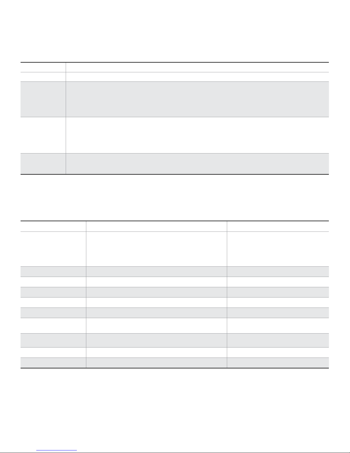
Table 3. Environmental Specifications
Characteristic Condition Parameter
EMI:
radiated immunity
bulk current injection
ESD
Operating temperature — -40°C to 150°C [-40°F to 302°F]
Thermal shock, air to air -40°C to 150°C [-40°F to 302°F], 60 min. soak, <3 s transfer 500 cycles
Humidity 95% humidity at 38 °C [100 °F] 240 hr
Salt fog 5% salt solution by mass at 35 °C [95 °F] 96 hr
Thermal saline dunk 100°C to 25°C [212°F to 77°F] air to liquid, 5% saline 10 cycles
High temperature exposure with power
Vibration 3 perpendicular axes, 48 hr per axis
Degree of protection — IP69K
Resistance to fluids — general under-the-hood automotive fluids
ISO 11452-2, 400 MHz to 1 GHz
ISO 11452-4, 1 MHz to 400 MHz
ISO 10605, Section 9 conforms to CE Mark standards
EN60947-5-2:2007 and EN 60947-5-2/A1:2012
150°C [302°F], 13.5 Vdc, 1 kOhm load 500 hr
100 V/m
100 mA
±8 kV contact, ±15 kV air
29.28 GMS, 50 Hz to 2000 Hz
MIL-STD-202-214
NS
2 Sensing and Internet of Things
Quadrature Speed and Direction Sensors
Vs: Yellow wire
Ground: Black wire
Channel A: White wire
Channel B: Blue wire
SNG-QPLA-000
Load A
Load B
Power
Supply
(4.5 V to 26 V)
T
rel
channel
Vsupply
Vsupply
56.0 Max.
6]
Issue C
SNG-Q Series
32309314
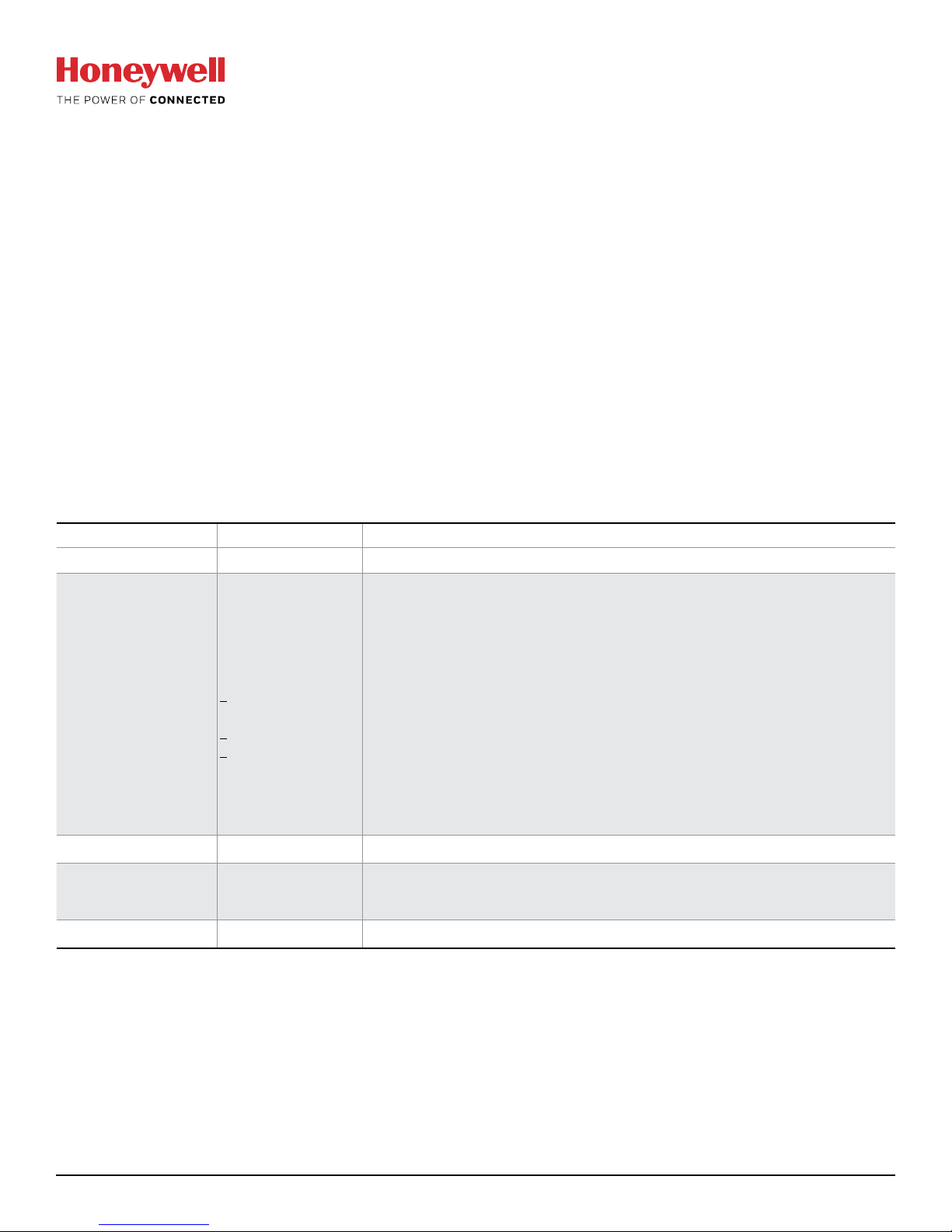
Figure 1. Sensor Output (All catalog listings) Figure 2. Possible Mounting Orientations
Output
channel A
(leading)
Phase shift
Output
channel B
(lagging)
arget cross section
ative to output
A
0° 0°
90°
Tooth
180°
270°
Slot
360°
Radial
Axial
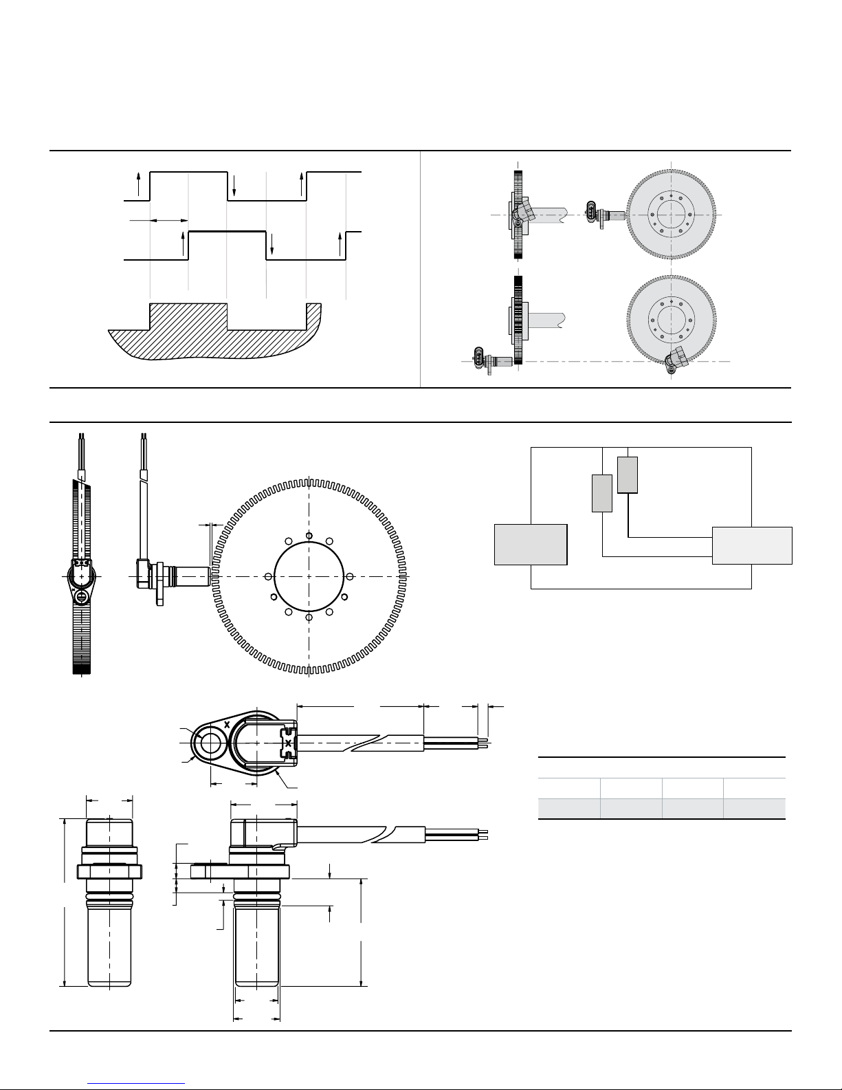
Figure 3. SNG-QPLA-000 Mounting Dimensions (For reference only: mm/[in].)
Circuit Diagram
[2.20]
15,0
[0.59]
2,0
[0.08]
Note: The load resistor values should be such
that the output current does not exceed the
maximum load current of 40 mA.
Use Ohm's Law to calculate the load resistor
based on the supply/load voltage used:
R = V / 0.04 A
500
ø6,20
[0.24]
ø13,00
[0.51]
[0.20]
4,50
[0.18]
5,00
2,50
[0.10]
15,0
[0.59]
21,5
[0.85]
ø21,00
[0.83]
8,50 - 9,00
[0.33 - 0.35]
[19.69]
34,95
[1.38]
23
[0.91]
4
[0.1
Leadwire Assignment
Yellow Black White Blue
Vsupply Ground Channel A Channel B
ø13,90
[0.55]
ø14,95
[0.59]
Sensing and Internet of Things 3
 Loading...