

Page 1
SMV800 SmartLine Multivariable Transmitter
Quick Start Installation Guide
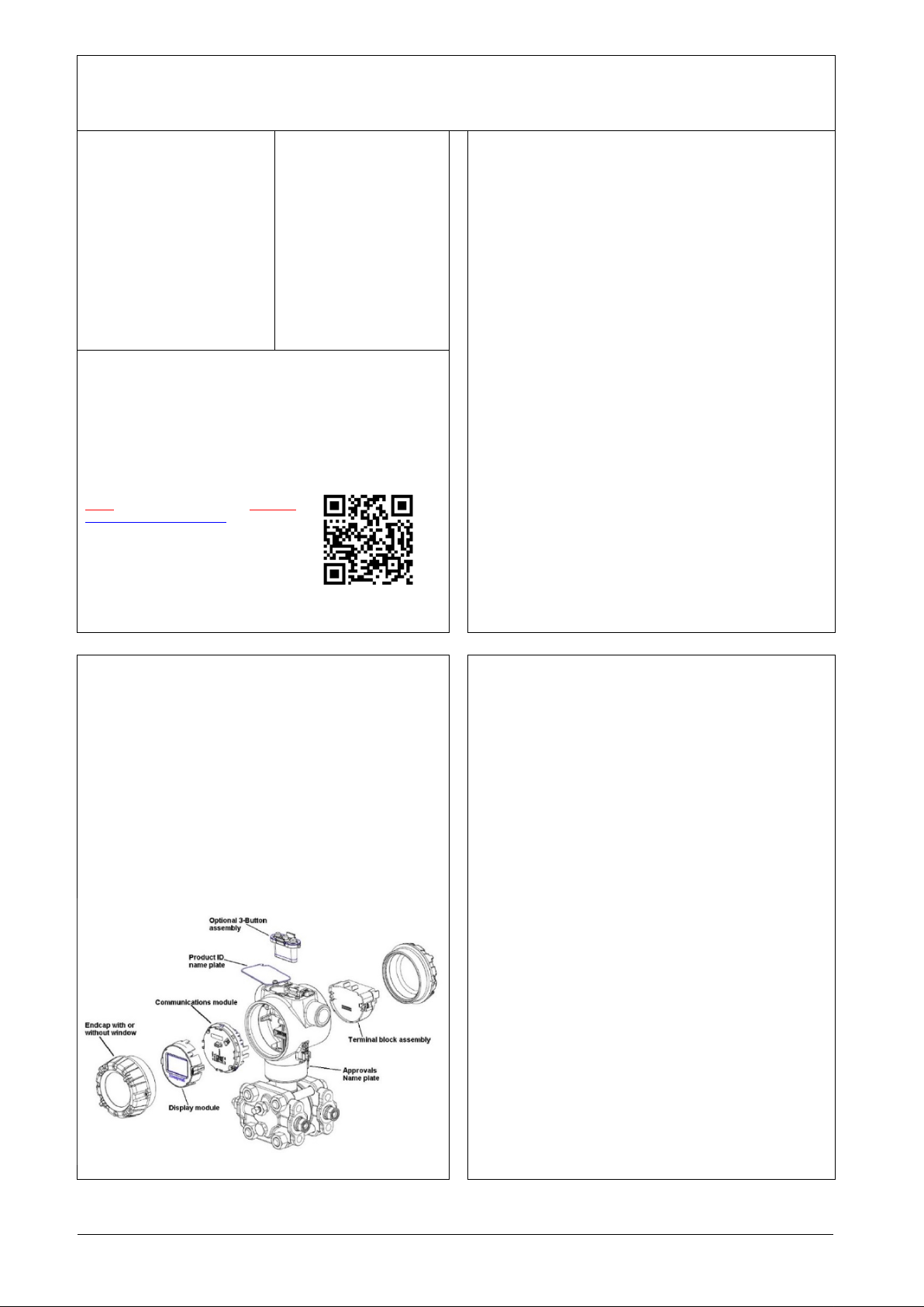
Figure 1: Electronic housing components
34-SM-25-04, Revision 8, November 2020
This document provides descriptions
and procedures for the quick
installation of Honeywell’s family of
SmartLine transmitters.
The SmartLine Multivariable
transmitter is available in a variety of
models for measuring differential
pressure, static press ur e, pro ces s
temperature, volume and mass flow
and Totalizer.
For full details refer to the man ual s
listed below for protocols , us er
Interface (HMI) operation, Install atio n,
configuration, calib ra ti on ,
maintenance, parts, and safety and
approvals etc. including options
Copyrights, Notices and
Trademarks.
Copyright 2020 by Honeywell
Revision 8, November 2020
Trademarks
SmartLine, SMV800 are U.S.
registered trademarks of
Honeywell Inc.
HART® is Trademarks of
FieldComm Group™
Documentation
To access complete documentation, including language variants, scan
the QR code below using your smart phone/device or QR code scanner.
Go to the APP store for your free Smartphone QR scanner
Or you can follow the URL to access the online SmartLine HUB page.
The HUB page will contain direct links to open SmartLine product
documentation.
URL QR Code
https://hwll.co/SmartLineHUB
Installation ................................................................................................................... 1
Features and Options ................................................................................................. 1
Mounting the Transmitter ............................................................................................ 2
Bracket mounting ................................................................................................. 2
Mounting bracket ................................................................................................. 2
Rotating Transmitter Housing .............................................................................. 2
Leveling Transmitters with Small Absolute or Differential Pressure Spans .......... 2
Conduit Entry Connectors, Plugs and Adapters .......................................................... 3
Wiring Connections and Power Up ............................................................................. 3
Wiring Variations .................................................................................................. 4
Explosion-Proof Conduit Seal ..................................................................................... 5
Tri m the Transmitter .................................................................................................... 5
Set of Jumpers for Modbus ......................................................................................... 6
Configuration Guide .................................................................................................... 6
Appendix A. PRODUCT CERTIFICATIONS ............................................................... 7
A3. Hazardous Locations Certifications (MSG Code from Table V) .................... 8
MODBUS Communications ........................................................................................ 9
WARNING: FOR CONNECTION IN AMBIENTS ABOVE 60oC USE WIRE
RATED 105oC ...................................................................................................... 9
Control Drawing ........................................................................................................ 10
Table 1: Conduit entry connectors and plugs .............................................................. 3
Table 2 - Conduit Adapters ......................................................................................... 3
Table 3: Wiring details for SMV Modbus Terminal block ............................................. 4
Table 4: AC Termination and Write Protect Jumpers for Modbus ............................... 6
Figure 1: Electronic housing components ................................................................... 1
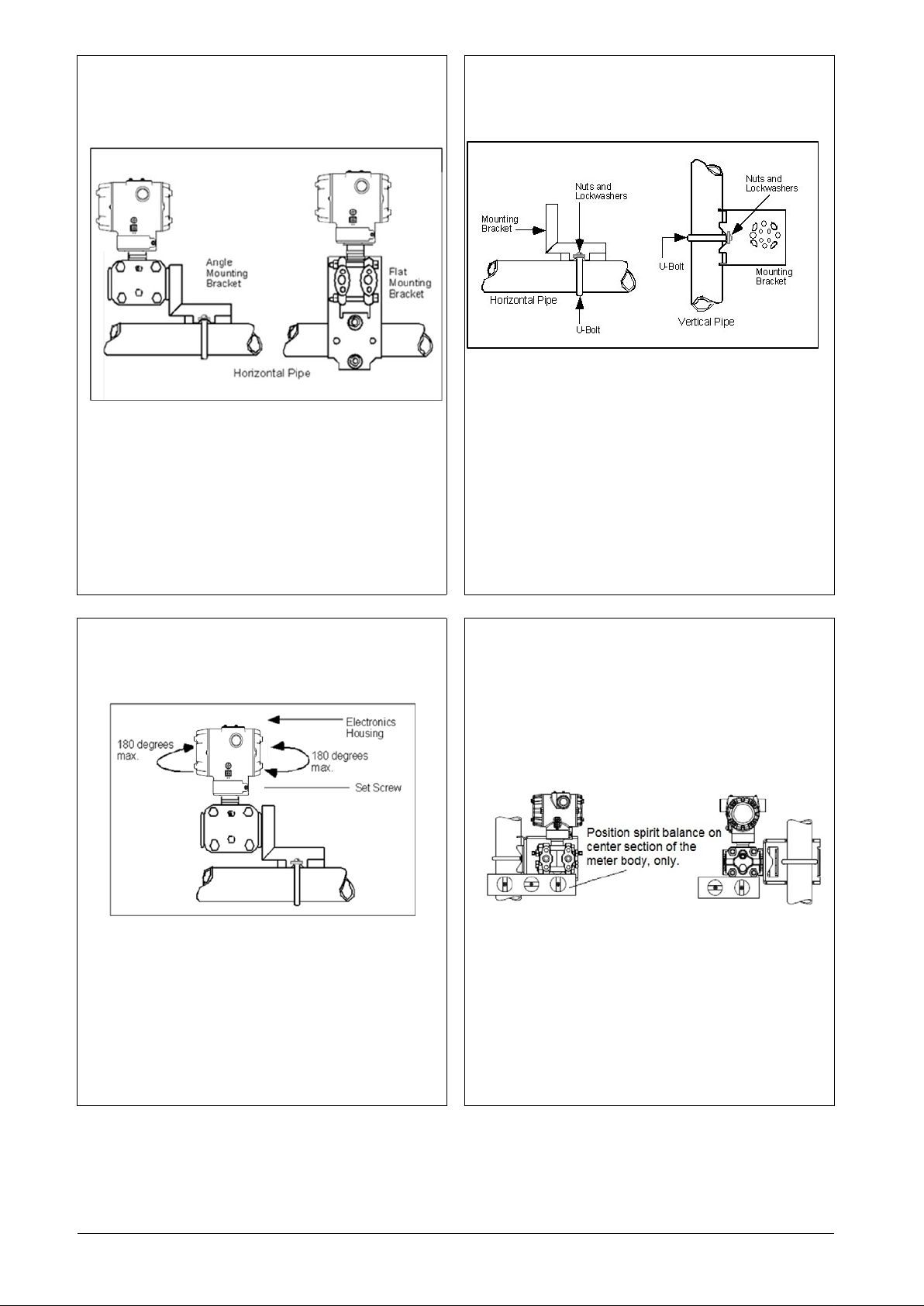
Figure 2: Mounting brackets ....................................................................................... 2
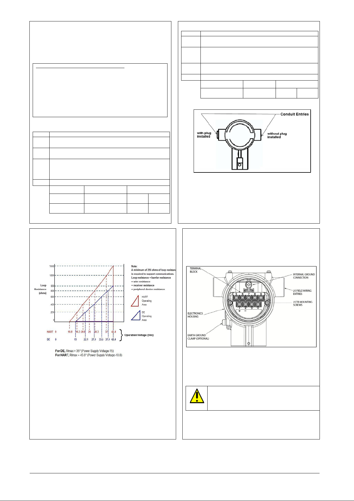
Figure 3: Angle mounting bracket ............................................................................... 2
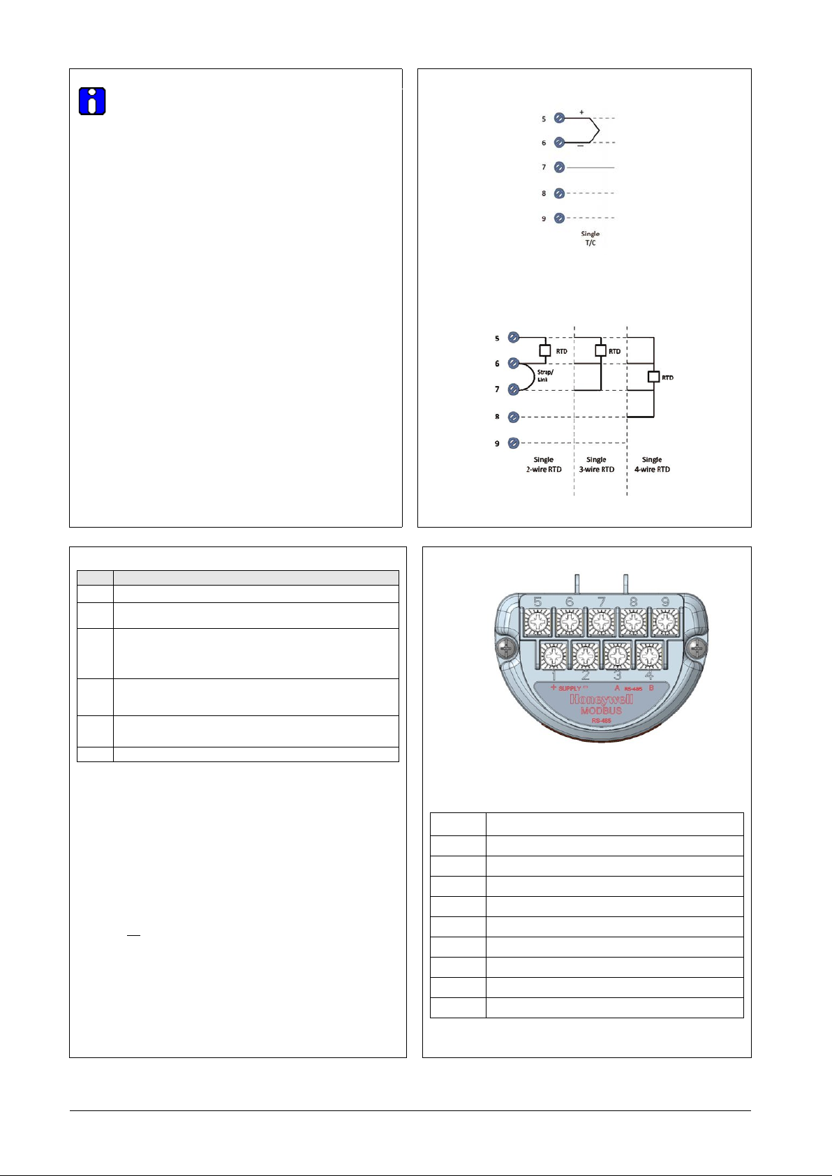
Figure 4: Rotating Transmitter Housing ...................................................................... 2
Figure 5: Using level to mount transmitter .................................................................. 2
Figure 6: Electronic Housing Conduit Entries ............................................................. 3
Figure 7: Two-wire power/current loop ........................................................................ 3
Figure 8: Terminal Block and Grounding Screw location ............................................ 3
Figure 9: Thermocouple connections .......................................................................... 4
Figure 10: RTD connections ....................................................................................... 4
Figure 11: Wiring details for SMV Modbus Terminal block ......................................... 4
Figure 12: Transmitter configuration via Modbus (RS-485) network port .................... 5
Figure 13: Jumper location HART ............................................................................... 6
Figure 14: Jumper settings HART ............................................................................... 6
Figure 15: Loading AC termination enable and write protect jumper for Modbus (RS-
485) ............................................................................................................................. 6
Table of Contents
Tables
Figures
Installation
Evaluate the site selected for the transmitter installation with respect to
the process system design specifications and Honeywell’s published
performance characteristics for your model.
Temperature extremes can affect display quality. The display can become
unreadable at temperature extremes; however, this is only a temporary
condition. The display will again be readable when temperatures return to
within operable limits.
Features and Options
The SMV800 is packaged in two major assemblies: the electronics
housing and the meter body. The elements in the electronic housing
respond to setup commands and execute the software and protocol for
the different pressure m eas urem e nt t ypes. Figure 1 shows the
assemblies in the electronics housing with available options.
The meter body provides connection to a process system. Several
physical interface configurations are available, as determined by the
mounting and mechanical connections.
The SMV800 SmartLine multivariable transmitter measures differential
pressure, static pressure (absolute or gauge), and process temperature.
These measurements are used to calculate volumetric or mass flow
rates. The measured values and calculated flow can be read by a
connected Host.
Available communication protocols are Honeywell Digitally Enhanced
(DE), HART and Modbus RTU. Digi tal or analog (4-20ma) output modes
are available. The SMV800 measures process temperature from an
external RTD or thermocouple.
Universal temperature input is available as a selectable feature with the
device or as license enabled, field upgradable option.
With Modbus protocol, Flow calculation capability also is available as
selectable feature with the device or as license enabled, field upgradable
option while this is a standard feature with HART and DE protocols
Device Variables
SMV800 supports 6 device variables:
1. Differential Pressure
2. Static Pressure
3. Process Temperature
4. Calculated Flow Rate
5. Totalizer
6. Meter Body Temperature.
For DE transmitters, Differential Pressure, Static Pressure, Process
Temperature or Flow ma y be assig ne d to analog output. In HART
transmitters, Differential Pressure, Static Pressure, Process
Temperature, Flow and Totalizer may be mapped to device variables PV
(analog output), SV, TV or QV and Meter Body temperature may be
mapped to SV, TV or QV. All six variables are Modbus process
variables.
SMV800 Quick Start Installation Guide 1
Page 2
Mounting the Transmitter
Mounting bracket
Transmitter models can be attached to a two-inch (50 millimeter) vertical
or horizontal pipe using Honeywell’s optional angle or flat mounting
bracket; alternately you can use your own bracket.
Typical bracket mount ed in st alla tions
Figure 2: Mounting brackets
Bracket mounting
Mounting bracket, see Figure 3
Rotate the transmitter housing, see Figure 4
Level a transmitter with small abs ol ut e or diff e re ntial pr ess ure sp ans , se e
Figure 5
Position bracket on 2-inch (50.8 mm) and install “U” bolt around pipe and
through holes in bracket. Secure with nuts and lock washers provided.
Figure 3 Example - Angle mounting bracket secured to horizontal or
vertical pipe.
Figure 3: Angle mounting bracket
Rotating Transmitter Housing
Use a 2mm hex wrench to loosen the set screw on outside neck of
transmitter one full turn. Rotate the transmitter housing to a maximum of
180 degree increment in left or right direction from center to position you
require and tighten set scre w (1. 46 to 1 .68 Nm / 13 to 15 lb-in).
Leveling Transmitters with Small Absolute or Differential Pressure Spans
Mounting position of these transmitters is critical due to the smaller
transmitter spans.
To minimize these positional effects on calibration (zero shift), take the
appropriate mounting precautions that follow for the given transmitter
model.
See figure below for suggestions on how to level the transmitter using a
spirit balance.
To perform a Zero Trim after leveling, refer to Trim the Transmitter.
Figure 4: Rotating Transmitter Housing
For a model SMA810 or SMA845 transmitters, you must ensure that the
transmitter is vertical when mounting it. You do this by leveling the
transmitter side-to-side and front-to-back.
Mount transmitter vertically to assure best accuracy. Position a spirit
balance on pressure connection surface of AP body.
Figure 5: Using level to mount transmitter
SMV800 Quick Start Installation Guide 2
Page 3
Conduit Entry Connectors, Plugs and Adapters
CONDUIT ENTRY PRECAUTIONARY NOTICE
AUTHORITIES AS APPLICABLE.
Step
Action
1
Remove the protective plastic cap from the threaded conduit
entry.
3
Thread the appropriate size conduit connector or plug (M20
adapters or reducers will be used .
4
Tighten plugs per the following table.
M20 Conduit
Entry
½” NPT
Conduit Entry
Step
Action
1
Remove the protective plastic cap from the threaded conduit
entry.
2
To ensure the environmental ingress rating on taper ed
used.
3
Thread the appropriate size adapter (M20 or ½ NPT) into
the conduit entry opening
½ to ¾ NPT
Adapter
power supply end.
Procedures
It is the user/installer’s responsibility to install the transmitters in
accordance with national and local code requirements. Conduit entry
plugs and adapters shall be suitable for the environment, shall be
certified for the hazardous location when required and acceptable to the
authority having jurisdiction for the plant.
THE CONDUIT/CABLE GLAND ENTRIES OF THIS PRODUCT ARE
SUPPLIED WITH PLASTIC DUST CAPS WHICH ARE NOT TO BE
USED IN SERVICE.
IT IS THE USER’S RESPONSIBILITY TO REPLACE THE DUST
CAPS WITH CABLE GLANDS, ADAPTORS AND/OR BLANKING
PLUGS WHICH ARE SUITABLE FOR THE ENVIRONMENT INTO
WHICH THIS PRODUCT WILL BE INSTALLED. THIS INCLUDES
ENSURING COMPLIANCE WITH HAZARDOUS LOCATION
REQUIREMENTS AND REQUIREMENTS OF OTHER GOVERNING
Use the following procedures for installation.
Wiring Connections and Power Up
Summary
The transmitter (HART/DE) is designed to operate in a two-wire
power/current loop with loop resistance and power supply voltage within the
HART/DE operating range shown below.
Table 1: Conduit entry connectors and plugs
2 To ensure the environmental ingress protection rating on
tapered (NPT), a non-hardening thread sealant may be used.
or ½” NPT) into the conduit entry opening. Do not install
conduit entry connectors or plugs in conduit entry openings if
Description Tool Torque
10mm Hex Wrench 32 Nm 24 Lb-ft
10mm Hex Wrench 32 Nm 24 Lb-ft
Table 2 - Conduit Adapters
threads (NPT), a non-hardening thread sealant may be
4 Tighten adapters as per the following table.
Description Tool Torque
1 ¼” Wrench 32Nm 24Lb-ft
Figure 6: Electronic Housing Conduit Entries
Note. No conduit connectors or plugs come installed in the housings. All
housings come with temporary plastic dust protectors (red) installed and
are not certified for use in any installation.
After wiring the Transmitter as outline in the next sections, torque the screws to
1.1 Nm (10 lb-in)
Supply Voltage for SMV Modbus
Modbus (RS-485) Mod els : 9.5 V to 30 Vdc at terminals.
Power Consumption: Average power consumption is 70 mW at 9.5 V
Supply. This includes RS-485 communication at 9600 baud rate at a
rate of once per second without termination at room temperature.
Figure 7: Two-wire power/current loop
A minimum of 250 ohms of loop resistance is required to support
communications. Loop resistance = barrier resistance., + wire resistance,
=receiver resistance, +peripheral device
resistance
Loop wiring is connected to the tr ans m i tt er b y attaching the positive (+) and
negative (–) loop wires to the positive (+) and negative (–) terminals on th e
transmitter terminal block in the electronics housing shown in Figure 8.
Connect the loop power wirin g s hield to earth ground only at the power
supply end.
Figure 8: Terminal Block and Grounding Screw location
As shown above, each transmitter has an internal terminal to connect it
to earth ground. Optionally, a ground terminal can be added to the
outside of the Electronics Housing.
Screw terminals 1, 2, 3, 5, 6, 7 & 8 only required for single input,
terminals 4 and 9 are only used for a Modbus dev ic e
CAUTION: For proper operation of the transmitter,
grounding of the transmitter is mandatory. This minimizes
the possible effects of noise on the output signal and
affords protection against lighting and static discharge
An optional lightning terminal block can be installed in place of the nonlightning terminal block for transmitters that will be installed in areas
that are highly susceptible to lightning strikes. As noted above, the loop
power wiring shield shoul d onl y be co n nect ed to earth ground at the
SMV800 Quick Start Installation Guide 3
Page 4
Input Sensor Wiring
Loop Wiring (H ART/DE)
Step
Action
1
Remove the end cap cover from the terminal block end of the
3
Feed loop power leads through one end of the conduit
4
Connect the positive loop power lead to the positive (+)
5
6
Replace the end cap, and secure it in place.
Terminal
Number
Description
Wiring must comply with local co des, regulations and
ordinances. Grounding may be required to meet various
approval body certification, for example CE conformity. Refer
to Appendix A of this document for details.
The HART/DE transmitter is designed to operate in a 2-wire
power/current loop with loop resistance and power supply voltage within
the operating range; see Figure 7.
With an optional remote meter (for HART/DE), the voltage drop for this
must be added to the basic power supply voltage requirements to
determine the required transmitter voltage and maximum loop resistance.
Additional consideration is required when selecting intrinsic safety
barriers to ensure that they will supply at least minimum transmitter
voltage, including the re qui r ed 250 ohms of resistance (typically within
the barriers) needed for digital communications.
Wiring Variations
The above procedures are used to connect power to a transmitter. For
loop wiring and external wi rin g, det ai le d drawings are provided for
transmitter installation in
non-intrinsically safe areas and for intrinsically safe loops in hazardous
area locations.
The screw terminals suitable for wirings up to (16AWG)
- Shielded, twisted-pair cable such as Belden 9318 or equivalent must
be used for all signal/power wi rin g.
Note: If solid core wire is used strip insulation 1/4 in (6 mm). Once
inserted under the square washer the stripped portion should be
contained under the squa re was he r. If m ult i-str an de d wir e is use d, a
ferrule is to be used and the stripped wire should be in the insulated
portion of the ferrule. The ferrule can be also used on the solid core
wire.
- The cable shield must be connected at only one end of the cable.
Connect it to the power supply side and leave the shield insulated at the
transmitter side.
After wiring the Transmitter as outline in the next sections, torque the
screws to 1.1 Nm (10 lb-in).
Connect the input sensors as shown in Figure 9 below:
RTD Connections
o Resistance temperature detector (RTD) measurements use the 3 or
4 wire approach. The transmitter determines by itself if a 3 or 4 wire
RTD is connected when powered up.
Figure 9: Thermocouple connections
Figure 10: RTD connections
2
Power Supply Wiring (Modbus) Procedure
1. See Figure 8, for parts locations. Loosen the end cap lock
2. Remove the end cap cover from the terminal block end of the
3. Feed twisted pair shielded power supply leads through one
4. Connect the positive power supply lead to the positive (+)
5. Modbus communication wires can be fed through the sam e
6. Feed input sensor wires through the 2nd conduit entrance and
7. Replace the end cap, and secure it in place.
See Figure 8, for parts locations.
electronics housing.
entrances on either side of the electronics housing. The
transmitter accepts up to 16 AWG wire. Shield of the cable to
be grounded on the supply/host side.
terminal and the negative loop power lead to the negative (-)
terminal. Note that the transmitter is not polarity-sensitive.
Feed input sensor wires through the 2nd conduit entrance and
connect wire.
using a 1.5 mm Allen wrench.
electronics housing.
end of the conduit entrances on either side of the electronics
housing. The transmitter accepts up to 16 AWG wire. Shield of
the cable to be grounded on the Supply/Host side.
terminal (Terminal #1) and negative power supply lead to the
negative (-) terminal (Terminal #2). Note that the transmitter is
not polarity-sensitive.
conduit that is being used for feeding power supply inputs. For
details related to Modbus connection refer to Table 3 and the
section on SMV Modbus Half-Duple x Modb us (R S-485) Wiring
Procedure.
connect wire.
Figure 11: Wiring details for SMV Modbus Terminal block
Table 3: Wiring de ta i ls for SM V Modbus Termina l bl ock
1 Power Supply input +ve
2 Power Supply input -ve (Return)
3 Modbus (RS-485) A
4 Modbus (RS-485) B
5 Temperature Sensor Input
6 Temperature Sensor Input
7 Temperature Sensor Input
8 Temperature Sensor Input
9 Modbus (RS-485) Common
SMV800 Quick Start Installation Guide 4
Page 5

SMV Modbus Transmitter Connection to a PC based Modbus
the integrated circuits in the Transmitter PWAs are vulnerable to damage by
Step
Action
1
Attach the transmitter to the mounting bracket but do not
completely tighten the mounting bolts
2
3
Connect 24 Vdc power to the transmitter. For HART/DE,
connect a digital voltmeter to monitor the PV output.
4
Use applicable communicator to establish communications with
PC application
5
While reading the transmitter’s output on a communication
mounting bolts.
6
The local display or applicable communicator can be used to
tightened.
7
If a SMV Modbus transmitter is directly hooked up to DC
distributed lines, it is mandatory to use transmitters with lightening
protection option.
A wire from the earth ground clamp (ref. Figure 8) of transmitter must
be connected to earth ground to make the lightening protection
effective. Use a size 8 AWG or (8.37mm
for this connection.
SMV Modbus Half-Duplex Modbus (RS-485) Wiring Procedure
The Modbus A, Modbus B & Modbus Common inputs are applied to
terminals Terminal #3, Terminal #4 & Terminal #9 respectively.
A 3-wire approach for Modbus communication is recommended to
avoid potential difference related issues and to ensure error-free
communication bet we en driv ers and receivers. For Modbus
communication, minimum 24 AWG shielded twisted pair cable with
nominal characteristic impedance of 120 ohms is recommended. Shield
of the communication cable must be connected to chassis ground on
host side.
Modbus RS-485 network recommends to use Termination on either
side of the network. Typically, 120ohm DC termination on eit h er en ds
(Host side & at last device) are provi ded.
Alternately “AC Termination” feature can be enabled internal to the
device (refer Figure 12, Table 3), when transmitter is the last device in
the network. In this case, external termination (if any) at the transmitter
end needs to be removed.
Multiple termination (apart from both ends of the network), can cause
communication failure. For improved performance, DC termination is
recommended.
Ensure Power lines & Modbus Communication lines are not
swapped during installation/maintenance
2
) bare or green covered wire
.
After wiring the Transmit ter as o utli n e in the next sect io ns, tor q ue
the screws to 1.1 Nm (10 lb-in)
(RS-485) Host
For configuration of the Transmitter using Laptop/PC bas e d application
following wiring recommendation are to be followed:
• Supply voltage (9.5V to 30V DC) is to be fed between
Terminal #1 & Terminal #2.
• Sensor inputs can be connected on Terminal #5 to Terminal
#8 as per the Sensor type
• Isolated USB to RS-485 adaptor is recommended for
connecting between PC based Host and Transmitter
• Default configuration of Modbus communication parameters
unless otherwise changed is: Baud rate – 9600 bps, Parity –
None and Device address - 247.
Before connectin g t o the PC bas ed H os t the device needs to be
disconnected from external host (if any).
Isolated RS-485 USB adaptor is recommended when connecting
the transmitter to PC.
Figure 12: Transm it ter co nfi g urat io n via M od bus (RS-485) network
port
(Refer to Table 3: Wiring details for SMV Modbus Terminal block)
ATTENTION: Please take appropriate steps to avoid ESD damage;
stray static discharges.
Explosion-Proof Conduit Seal
When installed as explosion proof in a Division 1 Hazardous
Location, keep covers tight while the transmitter is energized.
Disconnect power to the transmitter in the non-ha zard ous area prior to
removing end caps for service.
When installed as non-incendive equipment in a Division 2 hazardous
location, disconnect power to the transmitter in the non-hazardous ar ea,
or determine that the location is non-hazardous befo re disconnecting or
connecting the transmit t er wi re s.
Transmitters installed as explosionproof in Class I, Division 1, Group A
Hazardous (classified) locations in accordance with ANSI/NFPA 70, the
US National Electrical Code, with ½ inch conduit do not require an
explosionproof seal for installation.
If ¾ inch conduit is used, a LISTED explosionproof seal to be installed in
the conduit, within 18 inches (457.2 mm) of the transmitter.
Trim the Transmitter
Procedure to trim the transmitter
For a transmitte r wit h a small differential pressure spa n, you must ensure
that the transmitter is vertical when mounting it. You do this by leveling the
transmitter side-to-side and front-to-back. See Figure 5 for suggestions on
how to level the transmitter using a spirit balance. You must also zero the
transmitter by following the steps in this table.
Connect a tube between the input connections in the high
pressure (HP) and low pressure (LP) heads to eliminate the
effects of any surrounding air currents.
the transmitter. For DE transmitter use the SmartLine
Configuration Toolkit (SCT3000).
For HART, use MCT404-FDC applic a tion or oth er HA R T
Communicator with ap plic a ble H on e yw ell DD's.
For MODBUS, use Honeywell’s SmartLine Modbus manager
tool or a voltmeter, position the transmitter so the output
reading is at or near zero, and then completely tighten the
perform the zero corrects. This corrects the transmitter for
any minor error that may occur after the mounting bolts are
Remove the tube from between the input connections, the
power, and the digital voltmeter or communication tool.
SMV800 Quick Start Installation Guide 5
Page 6

SET JUMPERS FOR HART/DE
Step
Action
1
Turn OFF transmitter power.
2
Loosen the end-cap lock, and unscrew the end cap from the
electronics side of the transmitter housing.
3
If applicable, carefully depress the tabs on the sides of the
preferred orientation of the display module in the window.
4
5
Screw on the end cap and tighten the end-cap lock.
6
Turn ON transmitter power.
Jumper Settings
Description
Write Protect = ON (Protected)
Figure 14: Jumper settings HART
Step
Action
1
Turn OFF transmitter power.
2
Loosen the end-cap lock, and unscrew the end cap from the
electronics side of the transmitter housing.
3
If applicable, carefully depress the tabs on the sides of the
preferred orientation of the display module in the window.
4
Set the AC Termination jumper to the desired action and the
jumper positioning.
5
Screw on the end cap and tighten the end-cap lock.
6
Turn ON transmitter power.
AC termination = OFF
Protected)
AC termination = ON
Protected)
AC termination = ON
(Protected)
AC termination = OFF
(Protected)
Setting failsafe direction and write protect jumpers
The SmartLine Multivariable transmitter (DE or HART) provides two
jumpers to set the desired failsafe action and write protect option. See
Figure 13.
The top jumper on the electronics module sets the failsafe direction. The
default setting is up-scale failsafe.
Upscale drives the loop to a value greater than 21mA while down scale
drives the loop to a value less than 3.8mA.
You can change the failsafe direction by moving the failsafe jumper (top
jumper) to the desired position (UP or DOWN).
The bottom jumper sets the write protect.
The default setting is OFF (Un-protected).
When set to the ON (Protected) position, changed configuration
parameters cannot be written to the transmitter.
When set to the OFF (Un-protected) position, changed configuration
parameters can be written to the transmitter.
ATTENTION: Electrostatic Discharge (ESD) hazards. Observe
precautions for handling electrostatic sensitive devices.
display module and pull it off.
If necessary, move the interface connector from the
communication module to the display module to provide the
Set the failsafe jumper (top jumper) to the desired action (UP or
DOWN). And the write protect jumper (Bottom jumper) to the
desired behavior (Protected or Unprotected) See Figure 14 for
jumper positioning.
Figure 13: Jumper location HART
Failsafe = UP (High)
Write Protect = OFF (Not Protected)
Failsafe = DOWN (Low)
Write Protect = OFF (Not Protected)
Failsafe = UP (High)
Write Protect = ON (Protected)
Failsafe = DOWN (Low)
Set of Jumpers for Modbus
The SmartLine Multivariable Modbus transmitter provides two jumpers to
set the desired AC Termination setting and write protect option. See
Figure 15.
ATTENTION: Electrostatic Discharge (ESD) hazards. Observe
precautions for handling electrostatic sensitive devices
display module and pull it off.
If necessary, move the interface connector from the
communication module to the display module to provide the
write protect jumper to the des ir ed be h av ior (Se e Figure 15 for
Table 4: AC Termination and Write Protect Jumpers for Modbus
Jumper Arrang em ents Description
(Disabled)
Write Protect = OFF (Not
(Enabled)
Write Protect = OFF (Not
(Enabled)
Write Protect = ON
(Disabled)
Write Protect = ON
Configuration Guide
This transmitter comes with a standard factory configuration. Consult the
nameplate for basic information.
Reconfiguration for your particular application can be accomplished by
following instructions in the Transmitter User’s manual.
This can be found by following the website URL or QR code on page 1 of
this document.
Figure 15: Load i n g AC ter m i nation enable a nd wr it e protect jumper
for Modbus (RS-485)
SMV800 Quick Start Installation Guide 6
Page 7

Appendix A. PRODUCT CERTIFICATIONS
SIL 2/3
IEC 61508 SIL 2 for non-redundant use and SIL 3 for redundant
use according to EXIDA and TÜV Nord Sys Tec GmbH & Co. KG
2010; IEC61508-3: 2010.
A1. Safety Instrumented Systems (SIS) Installations
For Safety Certified Installations, please refer to SMV800 SmartLine
Multivariable Safety Manual 34-SM-25-05 for installation procedure and
system requirements.
Certification
A2. European Directive Information (CE Mark)
under the following standards: IEC61508-1: 2010; IEC 61508-2:
SMV800 Quick Start Installation Guide 7
Page 8

MSG CODE/
AGENCY
TYPE OF PROTECT ION
Electrical
Parameters
Ambient
Temperature
Explosion proof:
IIIC T 95oC..T 115oC Db
Intrinsically Safe:
T4 Ga
Non-Incendive and
T4 Gc
Enclosure: Type 4X/ IP66/ IP67
Standards: FM 3600:2018; ANSI/ ISA 60079-0: 2013; FM
2003 ; ANSI/ IEC 60529 : 2004
Explosion proof:
T 95oC..T 115oC Db
Intrinsically Safe:
Ex ia IIC T4 Ga
Non-Incendive and
Class I Zone 2 AEx nA IIC T4 Gc
Enclosure: Type 4X/ IP66/ IP67
Standards:
CSA C22.2 No 25:2017; CSA
No 61010
CSA C22.2 No 213: 2017; CSA C22.2 No 60529:2016; CSA C22.2 No
60079
11:2014; CSA C22.2
12.12.01:2017; ANSI/UL 61010
0:2013(R2017); ANSI/ UL 60079
ANSI/ UL 60079
60079
2017; UL 913:2015; UL 916: 2015; FM3615: 2006; FM 3616: 2011; FM
3600: 2011; ANSI/UL 50E: 2015
Flameproof:
T 115oC Db
Intrinsically Safe:
II 1 G Ex ia IIC T4 Ga
Non Sparking and
II 3 G Ex ic IIC T4 Gc
Note 2
Standards: EN 60079-0: 2018; EN 60079-1 :2014; EN 60079-11:
2015/A1: 2018
Enclosure: IP66/ IP67
Intrinsically Safe:
Ex ia IIC T4 Ga
Non Sparking:
Ex ic IIC T4 Gc
Flameproof:
Ex tb IIIC T 95oC.. T 115 oC Db
Enclosure: IP66/ IP67
Standards: IEC 60079-0: 2017; IEC 60079-1:2014; IEC 60079-11:
2011; IEC 60079-7: 2018; IEC 60079-31: 2013; IEC 60079-26: 2014
Intrinsically Safe:
Ex ia IIC T4 Ga
Non Sparking:
Ex ic IIC T4 Gc
Flameproof:
Ex tb IIIC T 95oC..T 115 oC Db
Enclosure: IP66/ IP67
Intrinsically Safe:
Ex ia IIC Ga
Non Sparking:
Ex ic IIC T4 Gc
Flameproof:
Ex tb IIIC T 95oC..T 115 oC Db
Enclosure: IP66/ IP67
Standards: ABNT NBR IEC 60079-0:2013 (IEC 60079-0:2011); ABNT
26:2006);
ABNT NBR IEC 60079-31:2014 (IEC 60079-31:2013).
Intrinsically Safe:
Ex ia IIC T4 Ga
T4: -50oC to 70oC
Non Sparking:
Ex nA IIC T4 Gc
Flameproof:
Db
Enclosure: IP66/ IP67
Flameproof:
Ex tD A21 T 95oC..T 115oC
Intrinsically Safe:
Ex ia IIC Ga
Ex d IIC T6..T5 Ga/Gb
Ex tb IIIC T 95oC..T 115oC Db
T5: -50 ºC to 85ºC
T6: -50 ºC to 65ºC
Intrinsically Safe:
Ex ia IIC T4 Ga
Non Sparking:
2 Ex nA IIC T4 Gc
Enclosure : IP 66/67
II 1/ 2 G Ex db IIC T6..T5
Ga/Gb
T5: -50 ºC to 85ºC
T6: -50 ºC to 65ºC
T4: -50 ºC to 70ºC
FISCO
Enclosure : IP 66/67
1/ ATEX and
IECEx
Combined ATEX and IECEX
See codes C and D
HART and DE
Voltage= 11 to 42 V
Current = 4-20 mA Normal (3.8 – 23 mA Faults)
A3. Hazardous Locations Certifications
(MSG Code from Table V)
Class I, Division 1, Groups
A, B, C, D
Class I, Zone 0/1, AEx db
IIC T6..T5 Ga/Gb
A/
FM
ApprovalsTM
Dust Ignition Proof:
Class II, Division 1, Groups
E, F, G;
Suitable for Division 1,
Class III;
Class II, Zone 21, AEx tb
Class I, II, III, Division 1,
Groups A, B, C,
D, E, F, G
Class I Zone 0 AEx ia IIC
Intrinsically Safe:
Class I, Division 2, Groups
A, B, C, D
Class I Zone 2 AEx nA IIC
T4 Gc
Class I Zone 2 AEx ic IIC
3615:2018; ANSI/ ISA 60079-1 :2015; FM 3616: 2011 ; ANSI/ ISA
60079-31 :2015; FM 3610:2018; ANSI/ ISA 60079-11 :2014; FM
3810 : 2018; ANSI/ ISA 60079-26 :2017; FM 3611:2018; ANSI/
ISA 60079-15 : 2013; ANSI/ ISA 61010-1: 2004;NEMA 250 :
Note 1
Note 2 T4: -50oC to 70oC
Note 1 T4: -50oC to 85oC
T95 oC /T5: -50 ºC
to 85ºC
T6: -50 ºC to 65ºC
B/
CSACanada
Class I, Division 1, Groups A, B,
C, D
Dust Ignition Proof:
Class II, III, Division 1, Groups E,
F, G
Suitable for Division 1, Class III;
Zone 0/1, Ex db IIC T6..T5
Ga/Gb
Class I, Zone 0/1, AEx db IIC
T6..T5 Ga/Gb
Ex tb IIIC T 95oC.. T 115oC Db
Class II, Zone 21, AEx tb IIIC
Class I, II, III, Division 1, Groups
A, B, C,
D, E, F, G;
Intrinsically Safe:
Class I, Division 2, Groups A, B,
C, D
Ex nA IIC T4 Gc
CSA C22.2 No 0: 2010 (R2015); CSA C22.2 No. 0-M91;
-1: 2012 (R2017); CAN/ CSA-C22.2 N o.157: 1992(R20 16);
-0:2015; CSA C22.2 No 60079-1: 2016; CS A C22.2 60079-
-31 :2015; ANSI/ IEC 60529-2004(R2011); ANSI/UL 122701:
60079-15:2016; CSA C22.2 60079-31:2015; ISA
-15:2013(R2017); ANSI/ UL 60079-26 :2017; ANSI/ UL
Note 1
Note 2 T4: -50oC to 70oC
Note 1 T4: -50oC to 85oC
C22.2 No 30M; 1986(R2016);CSA C22.2
-1: 2016; ANSI/ UL 60079-
-1:2015; ANSI/ UL 60079-11:2014;
T5: -50 oC to 85oC
T6: -50 oC to 65 oC
Sira 15ATEX2039X
II 1/2 G Ex db IIC T6..T5
Ga/Gb
II 2 D Ex tb IIIC T 95oC..
Sira 15ATEX2039X
C/
ATEX
IECEx
Intrinsically Safe:
Sira15ATEX4040X
II 3 G Ex ec IIC T4 Gc
2012; EN 60079-31: 2014; EN 60079-26 :2015; ; EN 60079-7:
IECEx SIR 15.0022X
IECEx SIR 15.0022X
Ex ec IIC T4 Gc
D/
Ex db IIC T6..T5 Ga/Gb
E/
SAEx
(South
Africa)
Ex ec IIC Gc
Ex db IIC T6..T5 Ga/Gb
Note 1
Note 2 T4: -50oC to 70oC
Note 1
Note 2
Note 1
Note 2 (ic)
Note 1
Note 2
Note 1
Note 2 (ic)
Note 1
T5/ T95oC: -50 ºC to
85ºC
T6: -50 ºC to 65ºC
T4: -50oC to 85oC
T4: -50oC to 70oC
T4: -50oC to 85oC
T5: -50 ºC to 85ºC
T6: -50 ºC to 65ºC
T4: -50oC to 70oC
T4: -50oC to 85oC
T5: -50 ºC to 85ºC
T6: -50 ºC to 65ºC
G/
NEPSI
(CHINA)
H/
KOSHA
(Korea)
I/
EAC Ex
(Russia,
Belarus and
Kazakhstan)
K/
UATR
(Ukraine)
Notes
1. Operating Parameters:
2. See Control Drawing 50128060, on Page 10. Intrinsically Safe Entity
Parameters
Ex d IIC T6..T5 Ga/Gb
Ex tb IIIC Db T 95oC..T 115 oC
Ex d IIC T6..T5
Intrinsically Safe:
Ex ia IIC T4 Ga
Note 2
Note 1 T4: -50oC to 85oC
Note 1
Note 1
Note 2 T4: -50oC to 70oC
Note 1
Note 2 T4: -50 ºC to 70ºC
Note 1 T4: -50oC to 85oC
Note 1
Note 2
T5: -50 ºC to 85ºC
T6: -50 ºC to 65ºC
T5: -50 ºC to 85ºC
T6: -50 ºC to 65ºC
T4: -50oC to 45oC
Ex ec IIC T4 Gc
F/
INMETRO
(Brazil)
SMV800 Quick Start Installation Guide 8
Ex db IIC T6..T5 Ga/Gb
NBR IEC 60079-1:2009 (IEC 60079-1:2007); ABNT NBR IEC 6007911:2013 (IEC 60079-11:2011); ABNT NBR IEC 60079-15:2012 (IEC
60079-15:2010); ABNT NBR IEC 60079-26:2008 (IEC 60079-
Note 2
Note 1
Note 2 (ic)
Note 1
T4: -50oC to 70oC
T4: -50oC to 85oC
T5: -50 ºC to 85ºC
T6: -50 ºC to 65ºC
Page 9

MODBUS Communications
MSG
AGENCY
TYPE OF PROTECT ION
Ambient Temperature
Explosion proof:
T 95o.. T 115oC Db
C
Non-Incendive
Class I Zone 2 AEx nA IIC T4 Gc
Enclosure: Type 4X/ IP66/ IP67
Standards: FM 3600:2018; FM 3610: 2018; ANSI/ ISA 60079-0:
1: 2004;NEMA 250 : 2003 ; ANSI/ IEC 60529 :
2004
Explosion proof:
T 115oC Db
Non-Incendive
Class I Zone 2 AEx nA IIC T4 Gc
Enclosure: Type 4X/ IP66/ IP67
Standards: CSA C22.2 No 0: 2010(R2015); CSA C22.2 No. 94-M91;
26: 2016;
-
2006; FM 3600: 2011; ANSI/UL 50E: 2015
Flameproof:
Non Sparking
Standards: EN 60079-0: 2018; EN 60079-1 :2014; EN 60079-31:
Enclosure: IP66/ IP67
Non Sparking:
T4: -50oC to 85oC
Flameproof:
Ex tb IIIC T 95oC.. T 115 oC Db
Enclosure: IP66/ IP67
Standards: IEC 60079-0: 2017; IEC 60079-1 :2014;
W/ ATEX
Combined ATEX and IECEX
Voltage= 9 to 32 V
Current= 30 mA
A4. Marking ATEX Directive
Protection type
Temperature Class
T4
Ex ia
Ta = -50°C to 70°C or -50°C to 45°C
Tp = -40 to 125°C
Ex ic
Ta = -50°C to 85°C or -50°C to 45°C
Tp = -40 to 125°C
Protectio
n type
Temperature Class
T4
T5
T6
Ex db
Ta = -50 to 85°C
Tp = -40 to 125°C
Ta = -50 to 85°C
Tp = -40 to 100°C
Ta = -50°C to 65°C
Tp = -40 to 85°C
A.5 continued …
Protection type
Temperature Class
T95°C…115°C/T4
Ex tb and Ex ec
Ta = -50 to 85°C
Tp = -40 to 115°C
CODE/
Class I, Division 1, Groups A, B, C, D
Class I, Zone 0/1, AEx db IIC T6..T5
Ga/Gb
Dust Ignition Proof:
Class II, Division 1, Groups E, F, G;
Suitable for Division 1, Class III;
Class II, Zone 21, AEx tb IIIC
6/
FM
ApprovalsTM
Class I, Division 2, Groups A, B, C, D
2013; FM 3615:2018; ANSI/ ISA 60079-1 :2015; FM 3616 : 2011 ;
ANSI/ ISA 60079-31 :2015; FM 3810 : 2018; ANSI/ ISA 6007926 :2017; FM 3611:2018; ANSI/ ISA 60079-15 : 2013; FM 3810 :
2005; ANSI/ ISA 61010-
T95 oC /T5: -50 ºC to 85º
T6: -50 ºC to 65ºC
T4: -50oC to 85oC
810/
ATEX
9/
IECEx
Sira 15ATEX2039X
II 1/2 G Ex db IIC T6..T5 Ga/Gb
II 2 D Ex tb IIIC T 95oC..T 115oC Db
Sira 15ATEX4040X
II 3 G Ex ec IIC T4 Gc
2014; EN 60079-26 :2015; ; EN 60079-7: 2015/A1: 2018
IECEx SIR 15.0022X
Ex ec IIC T4 Gc
Ex db IIC T6..T5 Ga/Gb
IEC 60079-7: 2018; IEC 60079-31: 2013; IEC 60079-26: 2014
T5/ T95oC: -50 ºC to
85ºC
T6: -50 ºC to 65ºC
T4: -50oC to 85oC
T5: -50 ºC to 85ºC
T6: -50 ºC to 65ºC
Class I, Division 1, Groups A, B, C, D
Dust Ignition Proof:
Class II, III, Division 1, Groups E, F, G
Suitable for Division 1, Class III;
Zone 0/1, Ex db IIC T6..T5 Ga/Gb
Class I, Zone 0/1, AEx db IIC T6..T5
Ga/Gb
Ex tb IIIC T 95oC..T 115oC Db
Class II, Zone 21, AEx tb IIIC T 95oC..
7/
CSACanada
And USA
Class I, Division 2, Groups A, B, C, D
Ex nA IIC T4 Gc
CSA C22.2 No 25:2017; CSA C22.2 No 30M; 1986(R2016);CSA No
61010-1: 2012(R2017); CSA C22.2 No 213: 2017; CSA C22.2 No
60529:2016; CSA C22.2 No 60079-0:2015; CSA C22.2 No 600791:2016;; CSA C22.2 60079-15:2016; CSA C22.2 No 60079CSA C22.2 60079-31:2015; ANSI/UL 12.12.01:2017; ANSI/UL 61010
1: 2016; ANSI/ UL 60079-0:2013(R2017); ANSI/ ISA 60079-1:2015;
ANSI/ UL 60079-15:2013(R2017); ANSI/ UL 60079-26 :2017; ANSI/
UL 60079-31 :2015; ANSI/IEC 60529: 2004(R2011); ANSI/ UL
913:2015; ANSI/ UL 916: 2015; ANSI/ UL 122701: 2017; FM 3615:
General:
The following information is provided as part of the labeling of the transmitter:
A.5 Conditions of Use” for Ex Equipment”, Hazardous Location
Equipment or “Schedule of Limitations”:
Apparatus Marked with Multiple Types of Protection
The user must determine the type of protection required for installation the equipment.
The user shall then check the box [] adjacent to the type of protection used on the
equipment certification nameplate. Once a type of protection has been checked on the
nameplate, the equipment shall not then be reinstalled using any of the other
certification types.
Intrinsically Safe: Must be installed per drawing 50128060
The enclosure is manufactured from low copper, aluminum alloy. In rare cases,
ignition sources due to impact and friction sparks could occur. This shall be considered
during installation, particularly if the equipment is installed in a Zone 0/ Division 1
location.
The applicable temperature class, ambient temperature (Ta) range and process
temperature (Tp) range of the equipment when installed with type protection “Ex ia”
and “Ex ic” are as follows:
Flameproof “db” and Explosionproof - The applicable temperature class, ambient
temperature (Ta) range and process temperature (Tp) range of the equipment when
installed with type protection “Ex db” are as follows:
The Transmitter can be installed in the boundary wall between an area of EPL Ga/
Class I Zone 0/ Category 1 and the less hazardous area, EPL Gb/ Class I Zone 1/
Category 2. In this configuration, the process connection is installed in EPL Ga/ Class I
Zone 0/ Category 1, while the transmitter housing is located in EPL Gb/ Class I Zone
1/ Category 2.
SMV800 Quick Start Installation Guide 9
• Name and Address of the manufacturer
• Notified Body identification: DEKRA Quality B.V., Arnhem, the
Netherlands
and IECEx
T5: -50 oC to 85oC
T6: -50 oC to 65 oC
T4: -50oC to 85oC
Notes
Operating Parameters:
FM Approval: Carbon disulphide is excluded for Ex d installations as the enclosure has
a volume greater than 100 cm3.
• FM Approval: For information on flameproof joint dimensions and repair,
• The installer shall provide transient over-voltage protection external to the
WARNING: DO NOT OPEN WHEN AN EXPLOSIVE ATMOSPHERE MAY BE
PRESENT
Dust ignition “tb” enclosure and non-sparking “ec” - The applicable temperature class,
ambient temperature (Ta) range and process temperature (Tp) range of the equipment when
installed with type prot ection “Ex tb” and “Ex ec” are as follows :
Non-Incendive Equipment:
Division 2: This equipment is suitable for use in a Class I, Division 2, Groups A, B, C,
D; T4 or Non-Hazardous Locations Only
WARNING: DO NOT OPEN WHEN AN EXPLOSIVE ATMOSPHERE MAY BE
PRESENT
WARNING: SUBSTITUTION OF COMPONENTS MAY IMPAIR SUITABILITY FOR
USE IN HAZARDOUS LOCATIONS
ALL PROTECTIVE MEASURES:
WARNING: FOR CONNECTION I N AMBIENTS ABOVE 60oC USE WIRE RA TED 105oC
Maximum permissible working pressure is 207 bar (3,000 psig).
If a charge-generating mechanism is present, the exposed painted metallic part on the
enclosure is capable of storing a level of electrostatic charge that could become
incendive for IIC/ Groups A, B, C or D gases. Therefore, the user/installer shall
implement precautions to prevent the build-up of electrostatic charge, e.g. earthing the
metallic part.
This is particularly important if the equipment is installed in a zone 0/ Division 1
location. Cleaning of the painted surface shall only be done with a damp cloth.
See codes 8 and 9
contact the manufacturer using instructions given in the user’s manual.
equipment such that the voltage at the supply terminal of the equipment
does not exceed 140 % of the voltage rating of the equipment.
Page 10

Control Drawing
SMV800 Quick Start Installation Guide 10
Page 11

For more information
Process Solutions
Honeywell
2101 City West Blvd,
Honeywell Control Systems Ltd
Shanghai City Centre, 100 Jungi Road
www.honeywellprocess.com
ASIA PACIFIC (TAC) hfs-tac-support@honeywell.com
9015
EMEA, Phone: + 80012026455 or +44 (0)1202645583. FAX: +44 (0) 1344 655554
Sales and Service
For application assistance, current specifications, pricing, or name of the nearest
Authorized Distributor, contact one of the offices below.
Australia Honeywell Limited, Phone: +(61) 7-3846 1255, FAX: +(61) 7-3840 6481
Toll Free 1300-36-39-36, Toll Free Fax: 1300-36-04-70
China – PRC – Shanghai, Honeywell China Inc. Phone: (86-21) 5257-4568,
Fax: (86-21) 6237-2826
Singapore, Honeywell Pte Ltd. Phone: +(65) 6580 3278. Fax: +(65) 6445-3033
South Korea, Honeywell Korea Co Ltd. Phone:+(822)799 6114. Fax:+(822) 792
Email: (Sales) sc-cp-apps-salespa62@honeywell.com
or (TAC) hfs-tac-support@honeywell.com
Web: Knowledge Base search engine http://bit.ly/2N5Vldi
AMERICAS, Honeywell Process Solutions, Phone: 1-800-423-9883,
or 1-215/641-3610. (TAC) hfs-tac-support@honeywell.com.
Sales 1-800-343-0228. Email: (Sales) ask-ssc@honeywell.com
Web: Knowledge Base search engine http://bit.ly/2N5Vldi
WARRANTY/REMEDY
Honeywell warrants goods of its manufacture as being free of defective materials and
faulty workmanship. Contact your local sales office for warranty information.
If warranted goods are returned to Honeywell during the period of coverage,
Honeywell will repair or replace without charge those items it finds defective.
The foregoing is Buyer's sole remedy and is in lieu of all other warranties,
expressed or implied, including those of merchantability and fitness for a
particular purpose. Specifications may change without notice.
The information we supply is believed to be accurate and reliable as of this printing.
However, we assume no responsibility for its use.
While we provide application assistance personally, through our literature and the
Honeywell web site, it is up to the customer to determine the suitability of the product
in the application.
To learn more about SmartLine Transmitters,
visit www.honeywellprocess.com
Or contact your Honeywell Account Manager
Houston, USA, TX 77042
Honeywell House, Skimped Hill Lane
Bracknell, England, RG12 1EB
Shanghai, China 20061
34-SM-25-04, Rev.8
November 2020
2020 Honeywell International Inc.
 Loading...