


SMV800 Series
HART/DE Option Manual
Use with SMV800 Multivariable Transmitter
34-SM-25-06
Revision 8.0
October 2020

Copyrights, No tices and Trademarks
© Copyright 2020 by Honeywe ll, Inc.
Revision 8, October 2020
While the information in this document is presented in good faith and believed to be
accurate, Honeywell disclaims any implied warranties of merchantability and fitness for a
particular purpose and makes no express warranties except as may be stated in the written
agreement with and for its customers. In no event is Honeywell liable to anyone for any
indirect, special, or consequential damages. The information and specifications in this
document are subject to change without notice.
Honeywell, TDC 3000, SFC, SmartLine, PlantScape, Experion PKS, MCT202, MCT404
and TotalPlant are registered trademarks of Honeywell International Inc. Other brand or
product names and service mark s are the property of their respective owners.
Honeywell Process Solutions
2101 City West Blvd
Houston, TX 77042
Page ii SMV800 Series HART/DE Option User’s Manual Revision 8.0

About This Manual
This manual provides the details of programming Honeywell SMV800 SmartLine Multivariable
Transmitters for applications involving HART and Digitally Enhanced (DE) communication
protocols. For instal lat ion , w irin g , an d mainten an ce information refer to the SMV800 SmartLine
Multivariable Transmitter User Manu a l, document number 34-SM-25-03.
The configuration of your Transmitter depends on the mode of operation and the options selected
for it with respect to operating controls, displays and mechanical installation. Details for
operations involving the Honeywell Multi-Communication (MC) Tookit (MCT404) and
SmartLine Configuration tool (SCT3000) are provided only to the extent necessary to accomplish
the tasks-at-hand. Refer to the associated
The SMV800 SmartLine Multivariable transmitter can be digitally integrated with one of two
systems:
• Experion PKS: you will need to supplement the information in this document with the data and
procedures in the Experion Knowledge Builder.
• Honeywell’s TotalPlant Solutions (TPS): you will need to supplement the information in this
document with the data in the PM/APM SmartLine Tra nsmitte r Integration Manual, which is
supplied with the TDC 3000 book set. (TPS is the evolution of the TDC 3000).
Release Information
SMV800 Series HART /DE Option User Manual, Document # 34-SM-25-06 (this document)
Rev. 1.0, October 2015 First Release (RQUP)
Rev. 2.0, December 2015 Prod release
Rev. 3.0, September 2016 Algorithm option updates
Rev. 4.0, December 2017 Totalizer functionality added (R120)
Rev. 5.0 March 2019 (R200)
Rev. 6.0 July 2019 DTM /DD structure update
Rev. 7.0 September 2020 SMG890 Added
Rev. 8.0 October 2020 Offline parameter values download configuration updated
References
The following list identifies publications that may contain information relevant to the information
in this document.
SMV800 SmartLine Multivariable Transmitter Quick Start Installation Guide, # 34-SM-25-04
SMV800 SmartLine Multivariable Transmitter Safety Manual w/ HART, 34-SM-25-05
SMV800 SmartLine Multivariable Transmitter User Manual, # 34-SM-25-03
MC Tookit User Manual (MCT404), Document # 34-ST-25-50
SCT3000, SmartLine Configuration Tool guide, Document # 34-ST-10-08
PM/APM SmartLine Transmitter Integration Manual, # PM 12-410
SMV800 Series Multivariable, Analog, HART Communications form, Drawing #50049892
Smart Field Communicator Model STS 103 Operating Guide, Document # 34-ST-11-14
Revision 8.0 SMV800 Series HART/DE Option User’s Manual Page iii
United States and
Canada
1-800-343-0228 Customer Service
1-800-423-9883 Global Technical Support
Global Email
Support
Honeywell Process
Solutions
Patent Notice
The Honeywell SMV800 SmartLine Multivariable Transmitter family is covered by one or more of
the following U. S. Patents: 5,485,753; 5,811,690; 6,041,659; 6,055,633; 7,786,878; 8,073,098; and
other patents pending.
Support and Contact Information
For Europe, Asia Pacific, North and South America contact details, see back page or refer to the
appropriate Honeywell Solution Support web site:
Honeywell Corporate www.honeywellprocess.com
Honeywell Process Solutions https://www.honeywellprocess.com/smart-multivariable-transmitters
Training Classes http://www.honeywellprocess.com/en-US/training
Telephone and Email Contacts
Area Organization Phone Number
Honeywell Inc.
ask-ssc@honeywell.com
Page iv SMV800 Series HART/DE Option User’s Manual Revision 8.0

Contents
1 SMV800 Physical and Functional Characteristics ......................................................................... 1
1.1 Overview ................................................................................................................................ 1
1.2 Features and Options .............................................................................................................. 1
1.2.1 Physical Characteristics .................................................................................................. 2
1.2.2 Functional Characteristics .............................................................................................. 3
1.3 Series, Model Series, Model and Number .............................................................................. 3
1.4 Safety Certification Information ............................................................................................. 4
1.5 Transmitter Adjustments ........................................................................................................ 4
1.6 Local Display Options ............................................................................................................ 5
1.7 Optional 3-Button Assembly .................................................................................................. 5
1.8 Universal Temperature Sensor Option Licensing .................................................................. 6
2 Communication Modes .................................................................................................................. 7
2.1 Overview ................................................................................................................................ 7
2.2 DE Mode Communication ...................................................................................................... 7
2.3 HART Mode Communication ................................................................................................ 9
3 Configuration Tools and Interfaces .............................................................................................. 10
3.1 Overview .............................................................................................................................. 10
3.2 Pre-requisites ........................................................................................................................ 10
3.3 Application Design, Installation, Startup, and Operation ..................................................... 10
3.3.1 Organization ................................................................................................................. 10
3.4 Toolkit Participation ............................................................................................................. 11
3.4.2 Toolkit Software Applications...................................................................................... 11
3.4.3 Configuration Databases .............................................................................................. 11
3.4.4 Configuration ................................................................................................................ 11
3.4.5 MC Toolkit–Transmitter Electrical/Signal Connections .............................................. 12
3.5 SmartLine Configuration Toolkit (SCT 3000) ..................................................................... 13
3.5.6 SmartLine Configuration Toolkit for use with DE models .......................................... 13
3.6 Considerations for SCT 3000 ............................................................................................... 14
3.6.7 SCT 3000 Requirements ............................................................................................... 14
4 Setting up Communications with the SCT3000 ........................................................................... 15
4.1 Establishing Communications .............................................................................................. 15
4.1.1 Off-line Versus On-line SMV Configuration ............................................................... 15
4.1.2 Off-line Configuration Procedures ............................................................................... 15
4.1.3 SCT Hardware Connections ......................................................................................... 15
4.1.4 SCT 3000 On-line Connections to the SMV ................................................................ 16
4.1.5 Establishing On-line Communications with the SMV ................................................. 17
4.1.6 Checking Communication Mode and Firmware Version ............................................. 18
4.1.7 DE Communication ...................................................................................................... 18
4.1.8 Changing Communication Mode.................................................................................. 18
5 DE Transmitter Configuration ...................................................................................................... 19
5.1 Configuration Personnel Requirements ................................................................................ 19
5.2 Configuration using the SCT3000 ........................................................................................ 19
5.2.1 SCT On-line Help and User Manuals ........................................................................... 19
5.3 About Configuration ............................................................................................................. 19
5.3.2 Configuration Summary ............................................................................................... 20
5.4 Using the SCT for SMV800 Configuration .......................................................................... 21
Revision 8.0 SMV800 Series HART/DE Option User’s Manual Page v

5.5 Device Configuration ........................................................................................................... 22
5.5.3 Transmitter Tag Name and PV1 Priority ..................................................................... 22
5.5.4 General Configuration .................................................................................................. 22
5.5.5 DPConf Configuration - PV1 ....................................................................................... 24
5.5.6 SP Conf Configuration - PV2 .................................................................................... 28
5.5.7 TempConf Configuration - PV3 ................................................................................ 30
5.5.8 FlowConf Configuration - PV4 ................................................................................. 35
5.5.9 Using Custom Engineering Units ................................................................................ 39
5.5.10 Flow Compensation Wizard (DE only)........................................................................ 40
5.6 Using the SCT3000 Tool to Configure Local Display Screens on SMV800 ....................... 42
5.6.11 Display Screen Configuration Instructions .................................................................. 42
5.6.12 Display Screen Configuration Parameters: .................................................................. 47
5.6.13 Saving, Downloading and Printing a Configuration File ............................................. 50
5.6.14 Verifying Flow Configuration ..................................................................................... 50
6 HART Transm itte r Co n figuration ................................................................................................ 51
6.1 Overview .............................................................................................................................. 51
6.1.1 Personnel Requirements ............................................................................................... 51
6.2 Overview of FDC Homepage .............................................................................................. 52
6.2.2 Settings ......................................................................................................................... 53
6.2.3 Manage DDs ................................................................................................................ 54
6.2.4 Online configuration .................................................................................................... 56
6.2.5 Offline configuration.................................................................................................... 56
6.2.6 Online Configuration Overview ................................................................................... 56
6.2.7 Overview of Device Homepage ................................................................................... 57
6.2.8 Tabs on the Device Home page ................................................................................... 57
6.2.9 Using FDC for various device operations .................................................................... 59
6.2.10 Procedure to Enter the Transm itter Tag ..................................................................... 116
6.2.11 Selecting Variable units of m easurement ................................................................... 116
6.2.12 Selecting Pressure Units ............................................................................................. 117
6.2.13 Selecting Temperature Units ...................................................................................... 117
6.2.14 Selecting Flow Units .................................................................................................. 118
6.2.15 Setting PV URV, and LRV Range Values (for Differential Pressure values) ........... 118
6.2.16 Setting Range Values for Applied Pressure for DP ................................................... 119
6.2.17 Setting URV, and LRV Range Values (for Static Pressure Values) .......................... 120
6.2.18 Setting Range Values for Applied Static Pressure ..................................................... 120
6.2.19 Setting URV, and LRV Range Values (for Temperature Values) ............................. 121
6.2.20 Setting Range Values for Applied Temperature ........................................................ 121
6.2.21 Entering URV, and LRV Range Values (for Flow Values) ....................................... 122
6.2.22 Saving device history ................................................................................................. 122
6.2.23 Exporting device history records to FDM .................................................................. 123
6.2.24 Exporting device history records to DocuMint .......................................................... 124
6.2.25 Custom Views ............................................................................................................ 124
6.2.26 Offline Configuration ................................................................................................. 126
7 DE Calibration ........................................................................................................................... 129
7.1 Overview ............................................................................................................................ 129
7.2 Calibration Recommendations ........................................................................................... 129
7.3 Test Equipment Required for Calibration .......................................................................... 129
7.4 DE Output Calibration ....................................................................................................... 130
7.4.1 Output Calibration Preparation .................................................................................. 130
7.4.2 Output Calibration using SCT3000 ............................................................................ 131
Page vi SMV800 Series HART/DE Option User’s Manual Revision 8.0

7.5 Calibrating Range Using a Configuration Tool .................................................................. 133
7.5.3 Conditions for Input Calibration................................................................................. 133
7.5.4 Input Calibration Procedures Description .................................................................. 133
7.6 DE Input Calibration Procedure ......................................................................................... 134
7.6.5 DP Input Cal ............................................................................................................... 134
7.6.6 Correct DP Input at the Lower Range Value (LRV) .................................................. 135
7.6.7 Correct DP Input at URV ........................................................................................... 137
7.6.8 AP Input Calibration ................................................................................................... 139
7.6.9 AP Input Cal LRV (Lower Range Value) Correct_ ................................................... 139
7.6.10 AP Input Cal URV (Upper Range Value) Correct ..................................................... 140
7.6.11 Reset Corrects ............................................................................................................. 140
7.6.12 Temperature Input Calibration ................................................................................... 141
7.6.13 Process Temperature LRV (Lower Range Value) Correct_ ....................................... 141
7.6.14 Process Temperature URV (Upper Range Value) Correct ......................................... 142
7.6.15 Reset Corrects ............................................................................................................. 142
8 HART Calibration ...................................................................................................................... 143
8.1 About This Section ............................................................................................................. 143
8.1.1 About Calibration ....................................................................................................... 143
8.1.2 Equipment Required ................................................................................................... 143
8.2 Analog Output Signal Calibration ...................................................................................... 144
8.3 Calibrating Range ............................................................................................................... 145
8.3.3 Correcting the Lower Range Value (LRV) for Differential pressure ......................... 145
8.3.4 Correcting the Upper Range Value (URV) for Differential Pressure ......................... 145
8.3.5 Resetting Calibration for Differential Pressure .......................................................... 147
8.3.6 Correcting the Lower Range Value (LR V) for T emperature ..................................... 147
8.3.7 Correcting the Lower Range Value (URV) for Temperature ..................................... 148
8.3.8 Resetting Calibration for Temperature ....................................................................... 149
8.3.9 Calibration Records .................................................................................................... 149
8.3.10 Dual / Triple Calibration ............................................................................................ 150
9 HART Advanced Diagnostics .................................................................................................... 151
9.1 About This Section ............................................................................................................. 151
9.2 Advanced Diagnostics ........................................................................................................ 151
10 Troubleshooting and Maintenance ......................................................................................... 152
10.1 Troubleshooting Using the SCT ......................................................................................... 152
11 Using DTMs ........................................................................................................................... 153
11.1 Introduction ........................................................................................................................ 153
11.2 Components ........................................................................................................................ 153
11.3 Downloads .......................................................................................................................... 153
11.4 Procedure to Install and Run the DTM ............................................................................... 153
11.5 SMV800 Online Parameterization...................................................................................... 154
11.5.1 Configuration Menu: .................................................................................................. 154
11.5.2 Monitoring Menu: ...................................................................................................... 155
11.5.3 Diagnostics Menu : ..................................................................................................... 155
11.5.4 Maintenance Menu: .................................................................................................... 155
11.6 Advanced Flow Setup (for DTM only) .............................................................................. 156
11.6.5 Engineering Units ....................................................................................................... 156
11.6.6 Flow Calculation Setup .............................................................................................. 159
11.6.7 Fluid Data Screen ....................................................................................................... 168
11.6.8 Coefficients and switches Screen ............................................................................... 176
11.6.9 Element Specific Properties screen ............................................................................ 185
11.7 Saving the current Online Configuration as Offline dataset ............................................... 191
11.8 SMV800 Offline Parameterization ..................................................................................... 192
Revision 8.0 SMV800 Series HART/DE Option User’s Manual Page vii

12 Comparison of configuration options from DD host vs DTM .............................................. 193
13 Flow Engineering Units Configuration for SMV800 HART and DE .................................... 194
13.1 SMV800 HART configuration using Pactware: ................................................................ 194
13.1.1 For Standard Flow Condition (Temperature: 15 °C, Pressure: 1.01325 barA): ......... 194
13.1.2 For Normal Flow Condition (Temperature: 0 °C, Pressure: 1.01325 barA): ............. 196
13.2 SMV800 DE Configuration using SCT3000 ..................................................................... 197
13.2.3 For Standard Flow Condition (Temperature: 15 °C, Pressure: 1.01325 barA): ......... 197
13.2.4 For Normal Flow Condition (Temperature: 0 °C, Pressure: 1.01325 barA): ............. 197
13.3 User defined Custom Units selection on SMV 800 DE Model.......................................... 198
14 Example Configuration of Flow for below specification: ...................................................... 200
15 HART DD binary file format compatibility matrix ............................................................... 208
16 Security .................................................................................................................................. 209
16.1 How to report a security vulnerability ............................................................................... 209
17 Troubleshooting ..................................................................................................................... 210
17.1 Diagnostic Messages for DE transmitters .......................................................................... 210
17.2 HART Diagnostic Message s .............................................................................................. 225
17.3 Flow Configuration Diagnostics, Messages and Values .................................................... 245
Appendix A. ....................................................................................................................................... 250
Glossary ............................................................................................................................................. 282
Page viii SMV800 Series HART/DE Option User’s Manual Revision 8.0

List of Figures
Figure 1 – SMV800 Major Assemblies .................................................................................................. 2
Figure 2 – Electronics Housing Components ......................................................................................... 2
Figure 3 –Typical Name Plate Information ............................................................................................ 3
Figure 4 – DE Communication through SCT ......................................................................................... 7
Figure 5 – DE Mode Value Scaling ....................................................................................................... 8
Figure 6 – HART Point-to-Point and Multi-drop Value Scaling ........................................................... 9
Figure 7 – MC Toolkit-Transmitter Electrical/Signal Connections ..................................................... 12
Figure 8 - SmartLine Configuration Tool ............................................................................................ 13
Figure 9 - SCT Hardware Components ................................................................................................ 16
Figure 10 - SMV On-line Configuration Process ................................................................................. 20
Figure 11 - Square Root Dropout Points for PV 1 ............................................................................... 27
Figure 12 – RTD Range Configuration ................................................................................................ 33
Figure 13 - Current Range Setting s ...................................................................................................... 34
Figure 14 - Typical Volumetric Flow Range Setting Values ............................................................... 37
Figure 15 - Low Flow Cutoff ............................................................................................................... 38
Figure 16 – FDC Homepage................................................................................................................. 52
Figure 17 – Device Homepage ............................................................................................................. 57
Figure 18 – Output Calibration Test Connections .............................................................................. 130
Figure 19 – DE Analog Mode Scaling and Test Connections ............................................................ 131
Figure 20 – Input Calibration Connections ........................................................................................ 134
Figure 21 - Setup to manually set the PV LRV and URV .................................................................. 146
Figure 22 - Typical Volumetric Flow Range Setting Values ............................................................. 189
Figure 23 – Low Flow cutoff action ................................................................................................... 190
Figure 24 - Engineering unitsTab ....................................................................................................... 204
Figure 25- Flow calculation setup tab ................................................................................................ 205
Figure 26 - Coeficients and switches .................................................................................................. 205
Figure 27 - Simulatio n tab .................................................................................................................. 206
Figure 28 - Fluid data ......................................................................................................................... 206
Figure 29 - Flow calculation setup ..................................................................................................... 207
Figure 30- Summary page .................................................................................................................. 207
Revision 8.0 SMV800 Series HART/DE Option User’s Manual Page ix

List of Tables
Table 1 – Features and Options.............................................................................................................. 1
Table 2 – Available Display Characteristics .......................................................................................... 5
Table 3 – User Manual Related Topics ................................................................................................ 10
Table 4 - Making SCT 3000 Hardware Connections ........................................................................... 16
Table 5 - Making SCT 3000 On-line Connections .............................................................................. 17
Table 6 - PV Type Selection for SMV Output ..................................................................................... 22
Table 7 - SMV Analog Output Selection ............................................................................................. 23
Table 8 - Pre-programmed Engineering Units for PV 1 ...................................................................... 24
Table 9 - Pre-programmed Engineering Units for PV2* ..................................................................... 28
Table 10 - Pre-programmed Engineering Units for PV3 ..................................................................... 30
Table 11 - Sensor Types for PV3 Process Temperature Input ............................................................. 31
Table 12- Pre-programmed Volumetric Flow Engineering Units for PV4 .......................................... 35
Table 13 - Pre-programmed Mass Flow Engineering Units for PV4 ................................................... 36
Table 14 - Primary Flow Elements ...................................................................................................... 40
Table 15 – Display Screen Configuration Parameters ......................................................................... 47
Table 16 - Display Screen configuration parameters details ............................................................... 48
Table 17 - FDC homepage elements .................................................................................................... 52
Table 18 - Device health status ............................................................................................................ 57
Table 19 - HART Transmitter Parameters ........................................................................................... 61
Table 20 - Configuration Menu ........................................................................................................... 63
Table 21 - Flow Calculation Setup ...................................................................................................... 78
Table 22 - Monitoring Menu ................................................................................................................ 99
Table 23 – Communication module diagnostics ................................................................................ 101
Table 24 - Meter Body (MB) diagnostics .......................................................................................... 103
Table 25 - Temperature Module diagnos tics ..................................................................................... 105
Table 26 - Write Tx Install date ......................................................................................................... 107
Table 27 - Write TM Install date ....................................................................................................... 107
Table 28 - Config History .................................................................................................................. 107
Table 29 - Fault history ...................................................................................................................... 107
Table 30 - Maintenance Menu ........................................................................................................... 108
Table 31 –Device Status .................................................................................................................... 112
Table 32 – Flow Units ........................................................................................................................ 115
Table 33 – Tamper Reporting Logic Implementation with Write Protect ......................................... 116
Table 34 – Viewing Advanced Diagnostics ....................................................................................... 151
Table 35 - Accessing SMV 800 Diagnostic Information using the SCT ........................................... 152
Table 36 – Unit Configuration ........................................................................................................... 157
Table 37 – Setup Flow Calculation .................................................................................................... 160
Table 38 - Configuration of Materials, Flowing Temperature and Thermal Expansion Coefficients 168
Table 39 – Fluid Data ........................................................................................................................ 169
Table 40 - Coefficients and Switches ................................................................................................ 177
Table 41 - Simulate Process Variables .............................................................................................. 183
Table 42 - Viscosity Coefficients: Dependency to Algorithm option ................................................ 183
Table 43 - Density Coefficients: Dependency to Algorithm option .................................................. 184
Table 44 - Element Specific Properties .............................................................................................. 187
Table 45 – Flow Parameters .............................................................................................................. 193
Table 46 – Flow Configuration parameters ....................................................................................... 200
Table 48 - HART DD binary file format compatibility matrix .......................................................... 208
Table 49 - Critical Status Diagnostic Message Table ........................................................................ 211
Table 50 - Non-Critical Status Diagnostic Message Table ................................................................ 214
Page x SMV800 Series HART/DE Option User’s Manual Revision 8.0

Table 51 - Communication Status Message Table ............................................................................. 220
Table 52 - Information Message Table............................................................................................... 222
Table 53 - SFC Diagnostic Message Table ................................................................................... 223
Table 53 – HART Critical D eta i ls ...................................................................................................... 225
Table 54 - Non-Critical 1 Diagnostic Details ..................................................................................... 232
Table 55 - Non-Critical 2 Diagnostic Details ..................................................................................... 237
Table 56 - Non-Critical 3 Diagnostic Details ..................................................................................... 240
Table 57 - Non-Critical 4 Diagnostic Details ..................................................................................... 244
Table 58 – Extended Device Status Diagnostic Details ..................................................................... 244
Table 59 - Air Through a Venturi Meter Configuration Example...................................................... 269
Table 60 - Superheated Steam using an Averaging Pitot Tube Configuration Example ................... 270
Table 61 - Liquid Propane Configuration Example ........................................................................... 273
Table 62 - Air Configuration Example ............................................................................................... 276
Table 63 - Superheated Steam Configuration Example ..................................................................... 279
Revision 8.0 SMV800 Series HART/DE Option User’s Manual Page xi

This page has been intentionally left blank
Page xii SMV800 Series HART/DE Option User’s Manual Revision 8.0

Communication Protoco ls
HART 7 and Digitally Enhanced (DE)
Human-Machine Interface
Advanced Digital Display
Three-button programming (optional)
Advanced display languages: English, German, French, Italian,
Calibration
Single, Dual and Triple Cal for PV1 (Diff.Pressure) and PV2 (Static
Pressure)
Approvals (See Appendix C
for details.)
ATEX, CSA, FM, IECEx, NEPSI
Mounting Brackets
Angle/flat carbon steel/304 stainless steel, Marine 304 stainless
steel
Integration Tools
Experion
1 SMV800 Physical and Functional Characteri st ics
1.1 Overview
This section is an in t roduction to the physical and functional characteristics of Honeywell’s family of
SMV800 SmartLine Multivariable Transmitters.
1.2 Features and Options
The SMV800 SmartLine M ult ivariable Tran smitter type SMV800 HART supports six device
variables: DP (Diff erential Pressu re ), SP (Static Pressure), PT (Process Tempera tu re), Flow and MBT
(Meter body Temperature), Totalizer and five dynamic variables: PV (Primary Variable), SV
(Secondary Variable), TV (Tertiary Variable) and QV (Quaternary Variable). Primary variable (PV)
can be configured as DP, SP, PT, Flow and Totalizer. Secondary Variable (SV), Tertiary Variable
(TV), Quaternary Variable (QV) can be configured as DP, SP, PT, Flow, MBT and Totalizer.
The dynamic variables can be set to any of the said device variables. Table 1 lists the protocols,
human interface (HMI), materials, approvals, and mounting bracket options for the SMV800
Transmitter.
Note: SMV800 DE model does not support Totalizer. All the other Device variables and dynamic
variables are supported as in HART model.
Table 1 – Features and Options
Feature/Option Standard/Available Options
(HMI)
Spanish, Russian, Turkish, Chinese & Japanese
Revision 8.0 SMV800 Series HART/DE Option User’s Manual Page 1
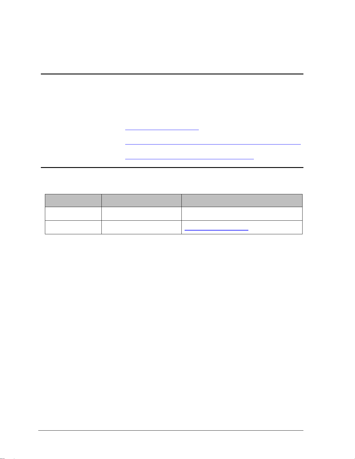
Physical Characteristics
As shown in
Figure 1, the SMV800 is packaged in two major assemblies: the Electronics Housing and the Meter
Body. The elements in the Electronic Housing respond to setup commands and execute the software
and protocol for the different pressure measurement types: DP (Differential Pressure), SP (Static
Pressure), PT (Process Tempera tur e) and MBT (Meter body Temperature).
The Meter Body provides connection to a process system. Several physical interface configurations
are available, as determined by the mounting and mechanical connections. Refer to the SMV800
SmartLine User’s manual, document #34-SM-25-03 for installation and wiring details.
Figure 1 – SMV800 Major Assemblies
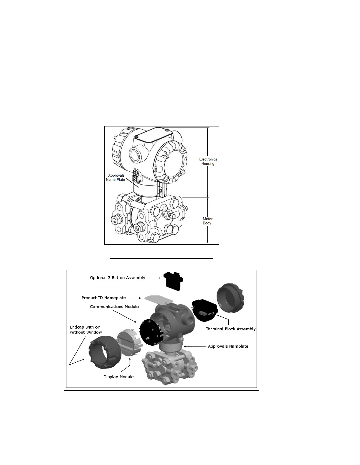
Figure 2 – Electronics Housing Components
Page 2 SMV800 Series HART/DE Option User’s Manual Revision 8.0
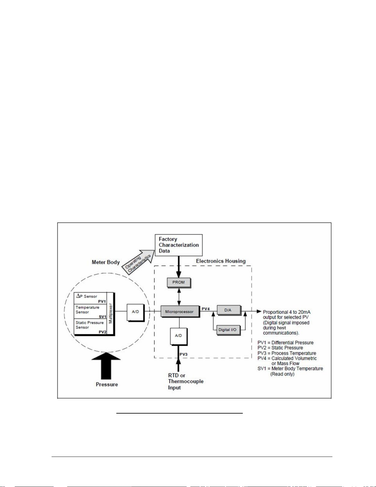
Functional Characteristics
The SMV800 SmartLine Multivariable transmitter measures Differential Pressure, Static Pressure
(Absolute or Gauge), and Process Temperature. These measurements are used to calculate volumetric
or mass flow rates. The measured values and calculated flow may be read by a connected Host.
Available communications protocols include Honeywell Digitally Enhanced (DE) and HART. Output
options include Digital and 4-20 mA Analog.
The SMV800 measures Process Temperature from an external RTD or Thermocouple.
The device may be configured to map any of the five Process Variable to the Analog Output (4-20
mA):
• Differential Pressure PV1
• Static Pressure PV2
• Process Temperature P V3
• Calculated Flow Rate PV4
• Calculated To ta lizer PV6
An optional 3-button assembly is available to set up and configure the transmitter via the Display. In
addition, a Honeywell MCT404/MCT202 Toolkit is available for configuration of HART models.
The SCT SmartLine Configuration Tool (not supplied with the Transmitter) can facilitate setup and
configuration for DE devices.
Certain adjustments can be m ade through an Experion Station or a Universal Station if the
Transmitter is digitally integrated with Honeywell’s Experion or TPS/TDC 3000 control system.
1.3 Series, Model Series, Model and Number
The Transmitter nameplate mounted on the top of the Electronics Housing (see
Figure 2) lists the model number, physical configuration, electronics options, accessories,
certifications, and manufacturing specialties.
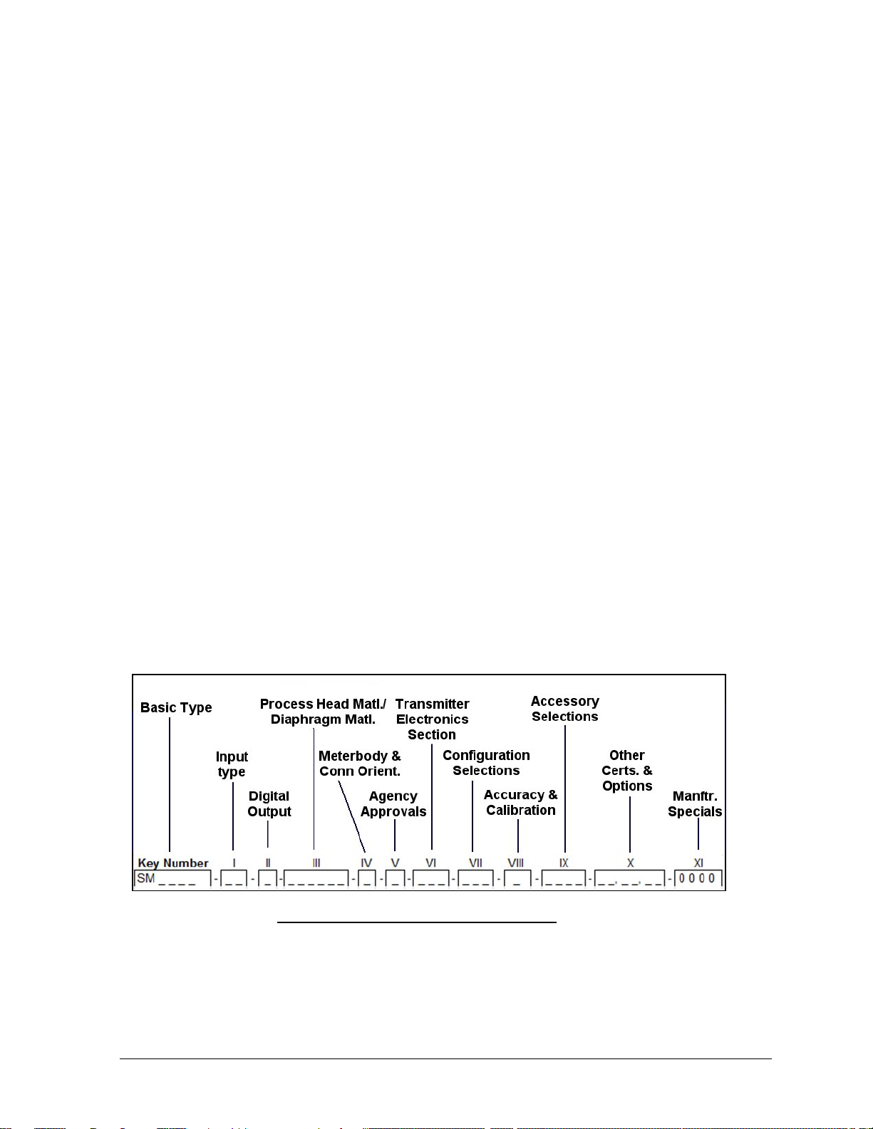
Figure 3 is an example of a typical SMV800 Transmitter name plate.
The model number format consists of a Key Number with several table selections.
Figure 3 –Typical Name Plate Information
Revision 8.0 SMV800 Series HART/DE Option User’s Manual Page 3

• A = Absolute Pressure
• G = Gauge Pressure
You can readily identify the series and basic Transmitter type from the third and fourth digits in the
key number. The letter in the third digit represents one of these basic measurement types for the Static
Pressure:
E.g. SMA810, SMA845, SMG870, SMG890
For a complete selection breakdown, refer to the appropriate Specification and Model Selection
Guide provided as a separate document.
1.4 Safety Certification Information
An “approvals” name plate is located on the bottom of the Electronics Assembly; see
Figure 1 for exact location. The approvals name plate contains information and service marks that
disclose the Transmitter compliance information. Refer to Appendix C of the SMV800 SmartLine
Transmitters User’s manual, document number 34-SM-25-03 for details.
1.5 Transmitter Adjustments
Zero and Span adjustments are poss ible in new generation SMV800 SmartLine Multivariable
Transmitters by using the optional thr ee-button assembly located at the top of the Electronic Housing
(see
Figure 2). However, certain capabilities are limited in the following configurations:
1. Without a display – Zero and Span setting only for HART and DE devices.
o Zero/Span button option works for DP, SP and PT when the same is mapped to
analog output accordingly. For example:
- If DP is mapped to AO, Zero/Span buttons options applied on DP.
- If SP is mapped to AO, Zero/Span buttons options applied on SP.
- If PT is mapped to AO, Zero/Span buttons options applied on PT.
- If Flow is mapped to AO, Zero button will perform DP zero correct operation*.
And for Span button it will not perform any operation
2. With a display – Complete Transmitter configuration is possible for HART and DE
devices.
* This feature is only available in HART R120 device.
You can also use the Honeywell MCT404 Configuration Tool – FDC application to make any
adjustments to an SMV800 Transmitter with HART.
For DE models the SCT3000 PC tool application can be used to configure the device.
Certain adjustments can also be made through the Experion or Universal Station if the Transmitter is
digitally integrated with a H oneywell Experion or TPS system.
SMV800 HART models can be configured using Honeywell tools such as Experion in conjunction
with FDM, using DTMs running in FDM or Pactware, or Emerson 375 or 475.
Page 4 SMV800 Series HART/DE Option User’s Manual Revision 8.0

• Screen Format
1.6 Local Display Options
The SMV800 Multivariable Transmitter has an Advanced display; see Table 2.
Table 2 – Available Display Characteristics
o Large process variable (PV)
o PV with bar graph
o PV with trend (1-24 hours, configurable)
• PV Selection
• Display Units
• Decimals
• PV Scaling
• Scaling Low
Advanced
Display
• Scaling High
• Display Low Limit
• Display High Limit
• Scaling Unit
• Screen Custom Tag
• Trend Duration (h)
• Language
o EN, FR, GE, SP, RU, IT & TU
o EN, CH (Kanji), JP
• PV Rotation,
• Sequence Time (sec)
1.7 Optional 3-Button Assembly
The optional 3-button assembly provides the following features:
• Opportunity for immediate reaction with minimal disruptions
• Improved maintenance time
• Potential savings on hand-held units
• Suitable for all environments: hermetically sealed for long life in harsh environments
• Suitable for use in all electrical classifications (flameproof, dustproof, and intrinsically safe)
The 3-button assembly is externally accessible and provides the following capabilities:
• Menu-driven configuration with optional display:
o Using increment, decrement & enter keys
o A comprehensive on screen menu guides the way
o Configure the transmitter
o Configure the display
o Set zero and span
• Zero and span settings without optional display
Revision 8.0 SMV800 Series HART/DE Option User’s Manual Page 5

1.8 Universal Temperature Sensor Option Licensing
In a standard device, only RTD Temperature sensor types may be used for measuring Process
Temperature.
The Universal Temperature Sensor option can be enabled after the transmitter is shipped by
purchasing and activating a license, to expand the selection of temperature sensor types to include
thermocouples.
For DE models, this option is only available at time of order entry and no license for activation is
supported.
To obtain and activate a license for the Universal Temperature Sensor option:
• Obtain the device's Serial Number from the local display menu or from the host interface.
• Place an order for Universal Temperature Sensor Field Upgrade for SMV 800, part number
#50127216-501 with the Serial Number.
• Based on this information the regional distribution center will generate and return a license
key.
• The license is activated by entering the License Key parameter value from the local display
menu or host interface.
• A restart of the display only will then occur.
• License activation can be confirmed by observing that the Universal Temperature Sensor
option is enabled using the local display menu or host interface.
Page 6 SMV800 Series HART/DE Option User’s Manual Revision 8.0
2 Communication Modes
2.1 Overview
The SMV800 SmartLine Multivariable Transmitter is available with either Honeywell's Digitally
Enhanced (DE) or HART revision 7 communications protocols. This manual address es the proc ess es
to configure and calibrate a Transmitter for DE and HART communication.
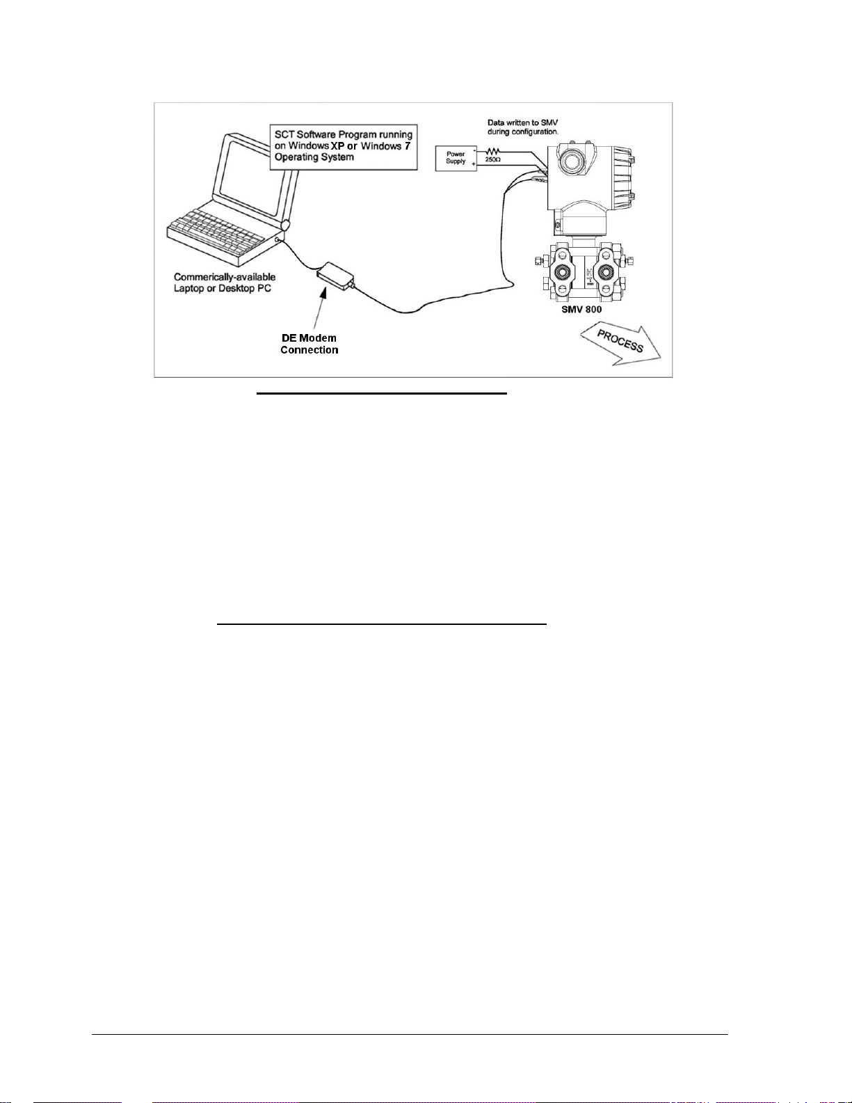
2.2 DE Mode Communication
The SMV800 can transmit its output in either an analog 4 to 20 milliampere format or a Digitally
Enhanced (DE) protocol format for direct digital communications with our TPS/TDC 3000 control
system. In the analog format, only a selected variable is available as an output which can be any one
of the following:
• Differential Pressure PV1,
• Static Pressure PV2,
• Process Temperature PV3, or
• Calculated Flow Rate PV4
Note that the secondary variable is only available as a read only parameter through the SCT shown in
Figure 4.
Figure 4 – DE Communication through SCT
Revision 8.0 SMV800 Series HART/DE Option User’s Manual Page 7
In the digital DE protocol format, all four process variables are available for monitoring and control
purposes; and the meter body temperature is also available as a secondary variable for monitoring
purposes only - See
Figure 4
The SMV800 transmitter has no phy sical adjustm ents. Y ou need an S CT to make any adjustments in
an SMV800 transmitter. Alternately, certain adjustments can be made through the Universal Station if
the transmitter is digitally integrated with our TPS/TDC 3000 control system.
For more information see section 3.5 SmartLine Configuration Toolkit (SCT 3000)
Digitally Enhanced (DE) Mode Communication
Although it is unnecessary to put a control loop in manual mode before communicating
with a Transmitter operating in DE mode, caution is required if there is potential for error in
identifying the operating mode.
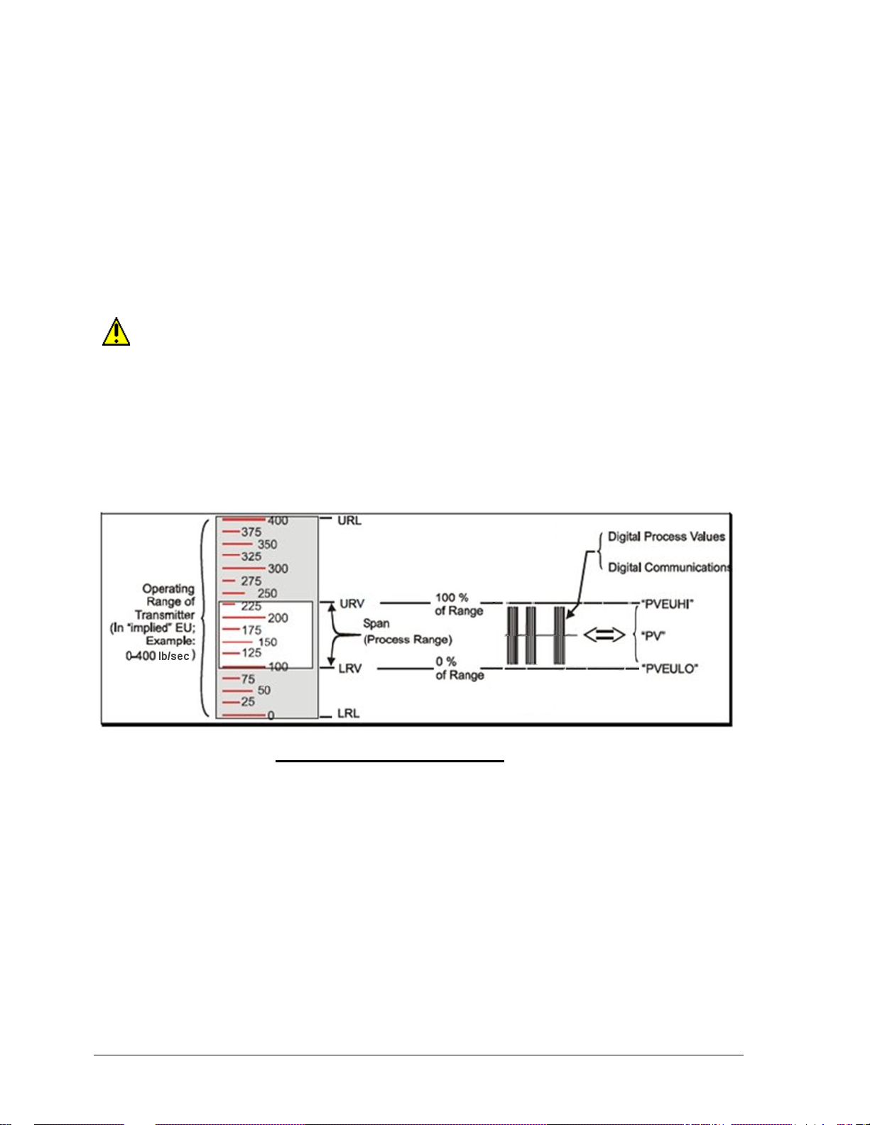
In DE mode, the PV is available for monitoring and control purposes.
Much of the operation in the Digitally Enhanced (DE) mode is similar to that of analog operation.
The essential characteristics of DE transmitter are shown in
Figure 5.
Figure 5 – DE Mode Value Scaling
As indicated at the r ig ht o f
Figure 5, output values of process vari abl es, as well as com munications are transferred to a receiv ing
device digitally. The digital coding is Honeywell proprietary, which requires the use of DE-capable
Honeywell control equipment.
The use of DE mode offers several advantages:
• Process Safety: Unlike analog mode, communications devices do not bump the PV value.
• Accuracy: requires less maintenance.
• Digital com munication: Relatively immune to small variations in circuit resistance or supply
voltage.
• Facilitates Maintenance Tasks: Honeywell control systems include operating displays that
enable direct communication with transmitters operating in DE mode.
Page 8 SMV800 Series HART/DE Option User’s Manual Revision 8.0
2.3 HART Mode Communication
When using MCT404,before connecting to a HART 7 transmitter, verify that the FDC
application is used and not the MC Toolkit application. For DE models use the SCT3000 PC
tool application.
• Transmitters with HART 7 capability have features that vary among manufacturers and with
the characteristics of specific devices. The FDC software application executing on the
MCT404/MCT202 supports the HART Universal, Common Practice and Device Specific
Commands which are implemented in the Honeywell Transmitters.
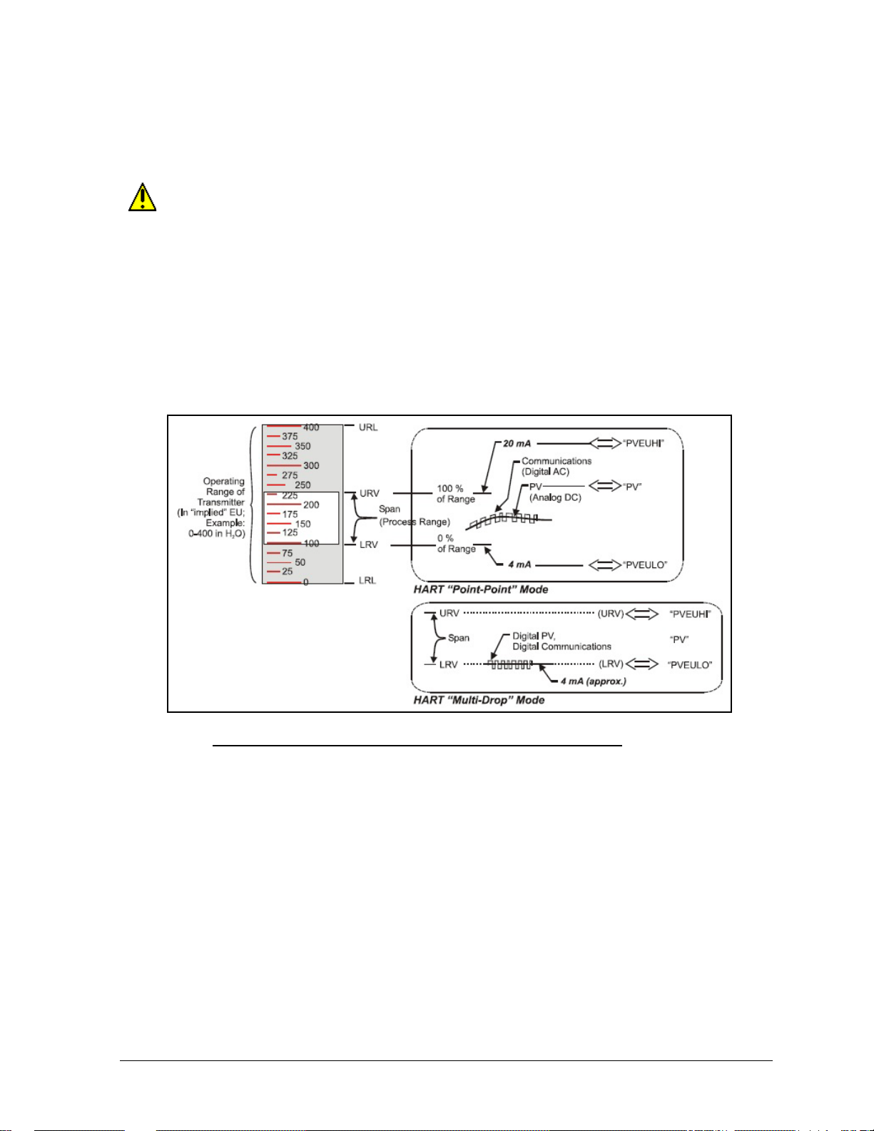
As indicated in
Figure 6, the output of a Transmitter configured for HART protocol includes two primary modes:
Figure 6 – HART Point-to-Point and Multi-drop Value Scaling
• Point-to-Point Mode, in which one Transmitter is connected via a two-conductor, 4-20 mA
current loop to one receiver.
• Multi-Drop Mode, in which several Transmitters ar e connected through a two-conductor
network to a multiplexed receiver device.
In point-to-point mode, the value of the primary Process Variable (PV) is represented by a 4-20 mA
current loop, almost identical to that of a Transmitter operating in analog mode. In this case, however,
the analog signal is modulated by Frequency Shift Keying (FSK), using frequencies and current
amplitude that do not affect analog sensing at the receiver. The accuracy of the analog level must be
precisely controlled for accurate sensing. HART communication will not bump process variables.
In multi-drop mode, up to 16 transmitters in HART 5 (addresses 0-15) and up to 64 transmitters in
HART6/7 (addresses 0-63) can exist on the two-conductor network.
Revision 8.0 SMV800 Series HART/DE Option User’s Manual Page 9

3 Configuration Tools and Interfaces
3.1 Overview
This section describes the tools and interfaces involved in configuring a new SMV800 SmartLine
Multivariable Transmitter for HART or DE communication operation. The information in this section
also applies to adjusting the configuration of a Transmitter that has been in operation and updating
one that is currently in operation.
3.2 Pre-requisites
The information and procedures in this manual are based on the assumption that personnel
performing configuration and calibration tasks are fully qualified and knowledgeable in the use of the
Honeywell MC Toolkit or MCT202/MCT404 and the PC tool SCT3000 application.
Furthermore, we assume that the reader is intimately familiar with the SMV800 family of SmartLine
Multivariable Transmitters and thoroughly experienced in the type of process application targeted for
Transmitter deployment. Therefore, detailed procedures are supplied only in so far as necessary to
ensure satisfactory completion of configuration tasks.
3.3 Application Design, Installation, Startup, and Operation
The SMV800 SmartLine Multivariable Transmitters User’s Manual, document number 34-SM-25-03,
provides the details for application design, installation, and startup; see Table 3 for topics.
Table 3 – User Manual Related Topics
SMV800 SmartLine Multivariable Transmitters User’s Manual, 34-SM-25-03
Section 2. Application Design Section 3. Installation and Startup Section 4. Operation
Safety
Accuracy
Diagnostics messages
Other sections include but not limited to: Section 5. Maintenance, Secti on 6. Cali brat ion, Sec ti on 7
Troubleshooting, Section 8. Parts List, Appendix. Certificates , Sec urity Vulnerability
Organization
This information in this section is arranged in the following sequence:
• MCT404 Toolkit operation in SMV800 Transmitter HART Setup and Configuration:
o Phy sical circu it conne ct ion s
o Application com ponents
o Configuration for Analog and HART operation
• SCT3000 operation in SMV800 Transmitter DE Setup and Configuration:
o Phy sical circu it conne ct ion s
o Application components
o Configuration for DE operation
Site evaluation, Toolkit issues
Display installation concerns,
Transmitter mounting, Piping &
wiring, Startup tasks and procedures
Three-button option
Failsafe direction setup
Monitoring displays
Page 10 SMV800 Series HART/DE Option User’s Manual Revision 8.0

3.4 Toolkit Participation
Before using the MCT404 Toolkit, be sure that you are aware of the potential
consequences of each procedure, and that you use appropriate safeguards to avoid possible
problems. For example, if the Transmitter is an element in a control loop, the loop needs to be
put in manual mode, and alarms and interlocks (i.e., trips) need to be disabled, as appropriate,
before starting a procedure.
Toolkit Software Applications
The MCT404 Toolkit – FDC software applications to work with SMV800 HART Transmitters and the
SCT3000 SmartLine Configuration tool for use configuring DE Transmitters:
• MCT404 Toolkit Field De vice Configurator (FDC). This application is used for configuring,
calibrating, monitoring, and diagnosing HART devices. FDC conforms to the IEC 61804-3
EDDL (Electronic Data Description Lang uag e) standa r d speci fication. The FDC application is
an open solution that supports devices with a reg istered device description (DD) file compatible
with HART Communication Foundation (HCF) requirements.
• SCT3000 tool. This application is used for configuring, calibrating, monitoring, and
diagnosing Honeywell Digitally Enhanced (DE) device s. For m ore info rm ation see section 3.5
SmartLine Configuration Toolkit (SCT 3000)
Details for work in g with the MC Toolkit are provided in the MC Toolkit User Manual, document
#34-ST-25-50 (MCT404). In subsequent sections of this manual, explicit operating instructions are
provided only in so far as necessary to complete required tasks and procedures. For SCT3000
application refer to User manual #34-ST-10-08
Configuration Databases
Both tools can be used to establish and/or change selected operating parameters in a Transm itter
database.
Configuration
Configuration can be accomplished both online and offline with the Transmitter powered up and
connected to the MC Toolkit. Online configuration imm ediately chang es the Tran sm itter ope rating
parameters. For offline configuration, Transmitter operating characteristics are entered into the
Toolkit memory for subsequent downloading to a Transmitter.
When you set up or configure a Transmitter, it can take up to 30 seconds for the value
to be stored in it. If you change a value and Transmitter power is interrupted before the
change is copied to nonvolatile memory, the changed value will not be moved to nonvolatile
memory.
Revision 8.0 SMV800 Series HART/DE Option User’s Manual Page 11
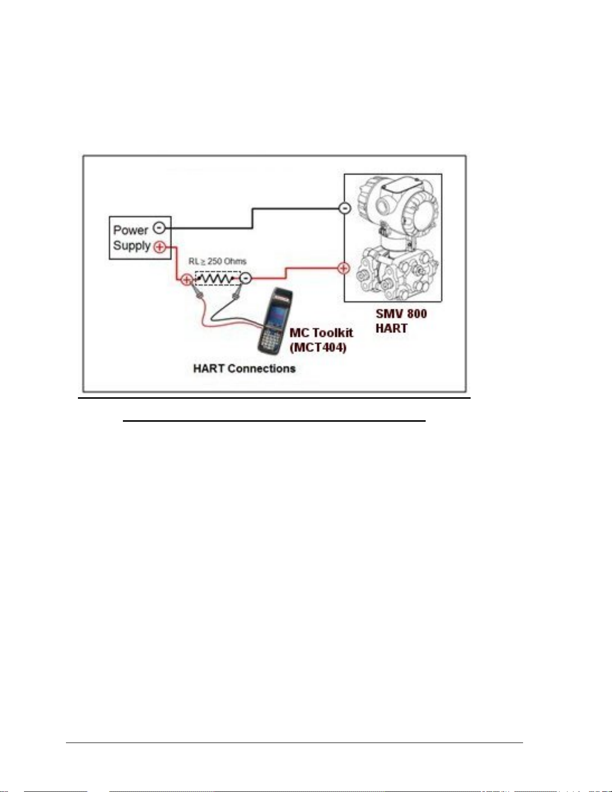
MC Toolkit–Transmitter Electrical/Signal Connections
Figure 7 displays how to connect the MC Toolkit directly to the terminals of a HART-only
Transmitter.
Figure 7 – MC Toolkit-Transmitter Electrical/Signal Connections
Page 12 SMV800 Series HART/DE Option User’s Manual Revision 8.0
3.5 SmartLine Configuration Toolkit (SCT 3000)
SmartLine Configuration Toolkit for use with DE models
Honeywell’s SCT 3000 SmartLine Configuration Toolk it is a cost-effective means to configure,
calibrate, diagnose, and monitor the SMV800 and other smart field devices. The SCT 3000 runs on a
variety of Personal Computer (PC) platforms using Windows XP
Microsoft Windows software and PC-interface hardware solution that allows quick, error-free
configuration of SMV transmitters. Figure 8 shows the major components of the SCT 3000.
Some SCT 3000 features include:
• Preconfigured templates that simplify configuration and allow rapid development of
configuration databases.
• Context-sensitive help and a comprehensive on-line user manual.
• Extensive menus and prompts that minimize the need for prior training or experience.
• The ability to load previously configured databases at time of installation.
• Automatic verification of device identification and database configuration menus and
prompts for bench set up and calibration.
• The ability to save unlimited transmitter databases on the PC.
®
and Window 7®. It is a bundled
Figure 8 - SmartLine Configuration Tool
Revision 8.0 SMV800 Series HART/DE Option User’s Manual Page 13

3.6 Considerations for SCT 3000
SCT 3000 Requirements
The SCT 3000 consists of the PC applicat ion and the H oney w ell DE Modem hard ware int erfac e used
for connecting the host computer to the SMV transmitter.
Be certain that the host computer is loaded with the proper operating system necessary to run the SCT
program.
See the SCT 3000 SmartLine Configuration Toolkit Start-up and Installation Manual #34-ST-10-08
for complete details on the host computer specifications and requirements for using the SCT 3000.
Page 14 SMV800 Series HART/DE Option User’s Manual Revision 8.0

4 Setting up Communications with the SCT3000
If you have never used an SCT to “talk” to an SMV800 transmitter, this section tells you how to
connect the SMV with the SCT, establish on-line communications and make initial checks.
ATTENTION
The SCT 3000 contains on-line help and an on-line user manual providing complete instructions for
using the SCT to setup and configure SMV transmitters.
4.1 Establishing Communications
Off-line Versus On-line SMV Configuration
The SCT 3000 allows you to perform both off-line and on-line configuration of SMV transmitters.
• Off-line configuration does not require connection to the transmitter. By operating the SCT
3000 in the off-line mode, you can configure and save database files of an unlimited number
of transmitters prior to receipt, and then download the database files, save them either to
portable media and then download the database files to the transmitters during
commissioning.
• An on-line session requires that the SCT is connected to the transmitter and allows you to
download previously-configured database files at any time during installation or
commissioning of your field application. Note that you can also upload a transmitter’s
existing configuration and then make changes directly to that database.
Off-line Configuration Procedures
Refer to the SCT User Man ual (on-line) for detailed procedures on how to off-line configure SMV
transmitters using the SCT 3000.
NOTE: The during offline download, it is important to have a valid set of configuration in the file in
order for the download to be successful (for Ex: in SMV800 DE device, when the Temperature
Sensor type is RTD, Internal CJ compensation is not applicable. So, make sure that CJ compensation
is set to External in the offline configuration).
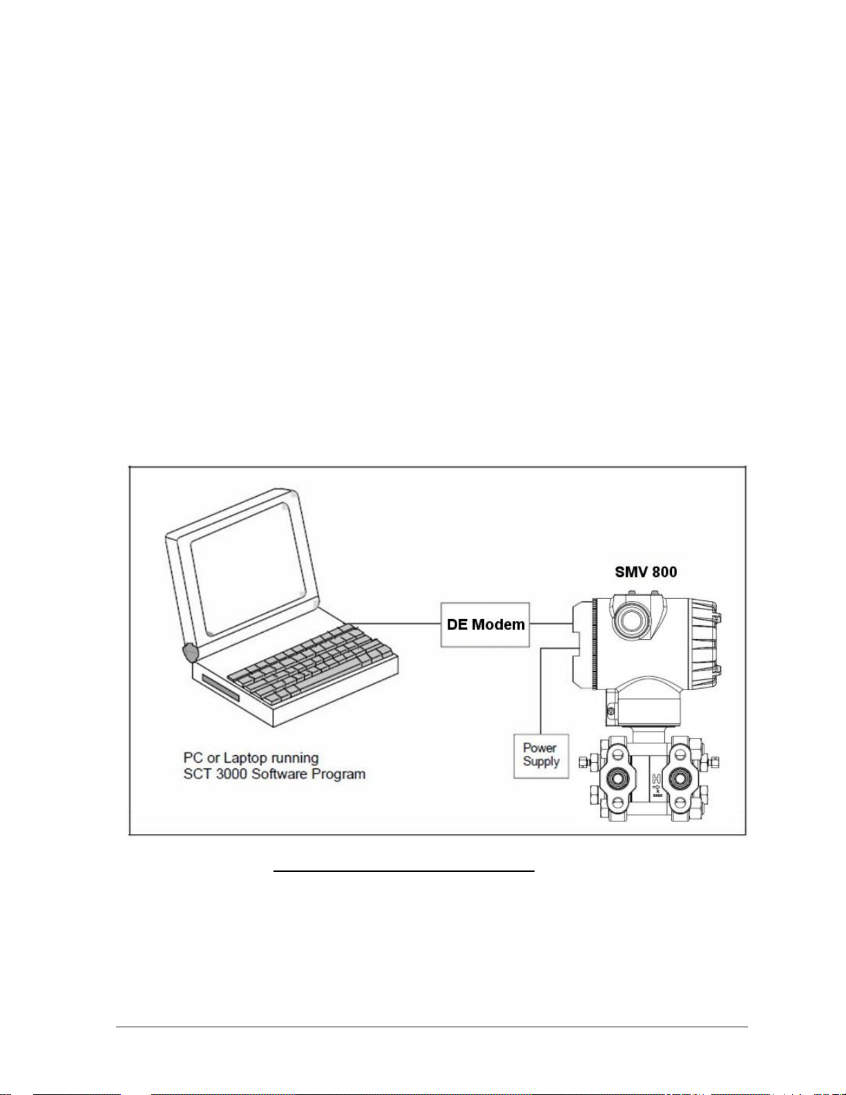
SCT Hardware Connections
A PC or laptop computer (host computer) which contains the SCT application is connected to the
wiring terminals of the SMV transmitter and other smart field devices via the Honeywell DE Modem.
Figure 9 shows the hardware components of the SCT.
Revision 8.0 SMV800 Series HART/DE Option User’s Manual Page 15
-- TMB-240 Single Slot Internal Front Panel Adapter
2
Remove the end-cap at the terminal block side of the SMV and
connect the easy hooks or alligator clips at the end of the adapter
Figure 9 - SCT Hardware Components
ATTENTION Connecting the host computer to an SMV for on-line communications requires
SmartLine Option Module consisting of a DE Modem connection.
SCT 3000 On-line Connections to the SMV
Table 4 provides the steps to connect the assembled SCT 3000 hardware between the host computer
and the SMV for on-line communications.
WARNING
When the transmitter’s end-cap is removed, the housing is not explosion proof.
Table 4 - Making SCT 3000 Hardware Connections
Step Action
1
With the power to the host computer turned off.
-- TM50 Dual Slot Internal Front Panel Adapter
-- GS-120 Greystone Peripherals, Inc.
-- GS-320 Greystone Peripherals, Inc.
cable to the respective terminals on the SMV as follows:
• Connect the red lead to the positive terminal.
• Connect the black lead to the negative terminal.
ATTENTION! The SCT 3000 can be connected to only one SMV at a time.
Page 16 SMV800 Series HART/DE Option User’s Manual Revision 8.0

manual for details (34-SM-25-03).
database configuration from the SMV.
the current
database configuration from the SMV and make the on
box displays prompting you to put the loop in manual and to check that all trips
Establishing On-line Communications with the SMV
Table 5 lists the steps to begin an on-line session with the loop-connected SMV and upload the
database configuration from the transmitter.
Table 5 - Making SCT 3000 On-line Connections
Step Action
1
2
3 Perform either step 4A (recommended) or 4B (but not both) to upload the current
4A • Select Tag ID from the View Menu (or click on the Tag ID toolbar button) to
4B Select Upload from the Device Menu (or click on the Upload toolbar button) to
Make sure that 24V dc power is applied to the proper SMV transmitter
SIGNAL terminals. For wiring details refer to the SMV800 Transmitter User’s
Apply power to the PC or laptop computer and start the SCT 3000 application.
access the View Tag dialog box.
--If the SCT 3000 detects that the transmitter is in analog mode, a dialog box
displays prompting you to put the loop in manual and to check that all trips
are secured (if necessary) before continuing. Click OK to continue.
-- After several seconds, the SCT 3000 reads the device’s tag
ID and displays it in the View Tag dialog box.
• Click on the Upload button in the View Tag dialog box to upload
-line connection.
-- A Communication s Status dialog box displays during the uploading
process.
upload the current database configuration from the SMV and make the on-line
connection.
-- If the SCT 3000 detects that the transmitter is in analog mode, a dialog
are secured (if necessary) before continuing. Click OK to continue.
-- A Communications Status dialog box displays during the uploading
process.
5
6 Refer to the SCT 3000 User Manual (on-line) for a procedure on how to
When the on-line view of the SMV appears on the screen, access the
Status form by clicking on its tab. The Status form is used to verify the status of
the connected field device.
• Separate list boxes for Gross Status and Det ailed Status are presented in
the Status form. Refer to the SCT 3000 User Manual (on-line) for explanations
of each status condition.
download any previously-saved configuration database files.
Revision 8.0 SMV800 Series HART/DE Option User’s Manual Page 17

Checking Communication Mode and Firmware Version
Before doing anything else, it is a good idea to confirm the transmitter’s mode of operation and
identify the version of firmware being used in the transmitter.
• Communication mode (either ANALOG or DE mode) is displayed on the Status Bar at the
bottom SCT application window.
• The transmitter’s firmware version is displayed on the Device configuration form
DE Communication
A transmitter in the digital (DE) mode can communicate in a direct digital
Mode fashion with a Universal Station in Honeywell’s TPS and TDC 3000 control systems. The
digital signal can include all four transmitter process variables and its secondary variable as well as
the configuration database.
Changing Communication Mode
You can select the mode you want the transmitter to communicate with the control system. The
communication mode is selected in the SCT General Configuration form tab card.
Page 18 SMV800 Series HART/DE Option User’s Manual Revision 8.0