

Page 1

SMV 3000
Smart Multivariable Transmitter
User’s Manual
34-SM-25-02
3/04
Page 2

Copyright, Notices, and Trademarks
© Copyright 1999 by Honeywell Inc.
Revision 0 – January 18, 1999
While this information is presented in good faith and believed to be accurate,
Honeywell disclaims the implied warranties of merchantability and fitness for a
particular purpose and makes no express warranties except as may be stated in its
written agreement with and for its customer.
In no event is Honeywell liable to anyone for any indirect, special or consequential
damages. The information and specifications in this document are subject to
change without notice.
This document was prepared using Information Mapping® methodologies and
formatting principles.
TotalPlant, TDC 3000 and SFC are U.S. registered trademarks of Honeywell Inc.
SmartLine is a U.S. trademark of Honeywell Inc.
Information Mapping is a trademark of Information Mapping Inc.
Other brand or product names are trademarks of their respective owners.
Honeywell
Industrial Automation and Control
Automation College
2820 West Kelton Lane
Phoenix, AZ 85023
ii SMV 3000 Transmitter User’s Manual 1/99
Page 3

About This Publication
This manual is intended as a detailed “how to” reference for installing, piping, wiring, configuring,
starting up, operating, maintaining, calibrating, and servicing Honeywell’s SMV 3000 Smart
Multivariable Transmitter. It is based on using the SCT 3000 Smartline
software version 2.0 or greater as the operator interface.
While this manual provides detailed procedures to assist first time users, it also includes
summaries for most procedures as a quick reference for experienced users.
Configuration Toolkit
If you will be digitally integrating the SMV 3000 transmitter with our TPS/TDC 3000
control
system, we recommend that you use the PM/APM Smartline Transmitter Integration Manual
supplied with the TDC 3000X bookset as the main reference manual and supplement it with
detailed transmitter information in Appendix A of this manual.
Note that this manual does not include detailed transmitter specifications. A detailed Specification
Sheet is available separately or as part of the Specifier’s Guide which covers all Smartline
transmitter models.
Conventions and Symbol Definitions
The following naming conventions and symbols are used throughout this manual to alert users of
potential hazards and unusual operating conditions:
ATTENTION
ATTENTION indicates important information, actions or procedures that
may indirectly affect operation or lead to an unexpected transmitter
response.
CAUTION
CAUTION indicates actions or procedures which, if not performed
correctly, may lead to faulty operation or damage to the transmitter.
WARNING
WARNING indicates actions or procedures which, if not performed
correctly, may lead to personal injury or present a safety hazard.
ElectroStatic Discharge (ESD) hazard. Observe precautions for handling
electrostatic sensitive devices.
Protective Earth terminal. Provided for connection of the protective earth
(green or green/yellow) supply system conductor.
1/99 SMV 3000 Transmitter User’s Manual iii
Page 4

iv SMV 3000 Transmitter User’s Manual 1/99
Page 5

Table of Contents
References ....................................................................................................................................xii
Technical Assistance...................................................................................................................xii
SECTION 1
1.1 Introduction.................................................................................................................... 1
1.2 CE Conformity (Europe) ................................................................................................ 3
1.3 SMV 3000 Smart Multivariable Transmitters ................................................................. 4
1.4 Smartline Configuration Toolkit (SCT 3000).................................................................. 7
1.5 Smart Field Communicator (SFC) ................................................................................. 8
1.6 Transmitter Order ........................................................................................................ 11
SECTION 2
2.1 Introduction.................................................................................................................. 13
2.2 Getting SMV 3000 Transmitter On-Line Quickly.......................................................... 14
SECTION 3
3.1 Introduction.................................................................................................................. 16
3.2 Considerations for SMV 3000 Transmitter................................................................... 17
3.3 Considerations for SCT 3000 ...................................................................................... 21
SECTION 4
4.1 Introduction.................................................................................................................. 23
4.2 Mounting SMV 3000 Transmitter................................................................................. 24
4.3 Piping SMV 3000 Transmitter...................................................................................... 29
4.4 Installing RTD or Thermocouple.................................................................................. 35
4.5 Wiring SMV 3000 Transmitter...................................................................................... 36
OVERVIEW - FIRST TIME USERS ONLY ................................................................ 1
QUICK START REFERENCE .................................................................................. 13
PREINSTALLATION CONSIDERATIONS............................................................... 16
INSTALLATION........................................................................................................ 23
SECTION 5
5.1 Introduction.................................................................................................................. 45
5.2 Establishing Communications...................................................................................... 46
5.3 Making Initial Checks................................................................................................... 50
5.4 Write Protect Option .................................................................................................... 51
SECTION 6
6.1 Introduction.................................................................................................................. 45
6.2 Overview...................................................................................................................... 47
6.3 Configuring the SMV 3000 with The SCT.................................................................... 50
6.4 Device Configuration.................................................................................................... 51
6.5 General Configuration.................................................................................................. 52
6.6 DPConf Configuration - PV1....................................................................................... 56
6.7 AP/GPConf Configuration - PV2................................................................................. 61
6.8 TempConf Configuration - PV3................................................................................... 64
6.9 FlowConf Configuration - PV4 ....................................................................................71
6.10 Using Custom Engineering Units................................................................................. 77
6.11 Flow Compensation Wizard......................................................................................... 78
6.12 Saving, Downloading and Printing a Configuration File............................................... 81
6.13 Verifying Flow Configuration........................................................................................ 82
GETTING STARTED ................................................................................................ 45
CONFIGURATION.................................................................................................... 45
1/99 SMV 3000 Transmitter User’s Manual v
Page 6

SECTION 7 STARTUP ................................................................................................................. 79
7.1 Introduction.................................................................................................................. 79
7.2 Startup Tasks............................................................................................................... 80
7.3 Running Output Check ................................................................................................ 81
7.4 Using Transmitter to Simulate PV Input....................................................................... 85
7.5 Starting Up Transmitter................................................................................................ 89
SECTION 8
8.1 Introduction.................................................................................................................. 93
8.2 Accessing Operation Data........................................................................................... 94
8.3 Changing Default Failsafe Direction ............................................................................ 98
8.4 Saving and Restoring a Database............................................................................. 102
SECTION 9
9.1 Introduction................................................................................................................ 103
9.2 Preventive Maintenance ............................................................................................ 104
9.3 Inspecting and Cleaning Barrier Diaphragms............................................................ 105
9.4 Replacing Electronics Module or PROM.................................................................... 108
9.5 Replacing Meter Body Center Section....................................................................... 113
SECTION 10
10.1 Introduction................................................................................................................ 111
10.2 Overview.................................................................................................................... 112
10.3 Calibrating Analog Output Signal............................................................................... 114
10.4 Calibrating PV1 and PV2 Range Values.................................................................... 115
10.5 Resetting Calibration.................................................................................................. 117
SECTION 11
11.1 Introduction................................................................................................................ 119
11.2 Overview.................................................................................................................... 120
11.3 Troubleshooting Using the SCT................................................................................. 121
11.4 Diagnostic Messages................................................................................................. 122
OPERATION............................................................................................................. 93
MAINTENANCE...................................................................................................... 103
CALIBRATION ..................................................................................................... 111
TROUBLESHOOTING.......................................................................................... 119
SECTION 12
12.1 Replacement Parts .................................................................................................... 137
SECTION 13
13.1 Wiring Diagrams and Installation Drawings............................................................... 147
APPENDIX A – PM/APM/HPM SMV 3000 INTEGRATION........................................................... 149
A.1 Overview.................................................................................................................... 149
A.2 Description................................................................................................................. 150
A.3 Data Exchange Functions.......................................................................................... 153
A.4 Installation.................................................................................................................. 160
A.5 Configuration ............................................................................................................. 162
A.6 Operation Notes......................................................................................................... 169
APPENDIX B
APPENDIX C —PV4 FLOW VARIABLE EQUATIONS................................................................. 175
C.1 Overview.................................................................................................................... 175
C.2 Standard Flow Equation............................................................................................ 176
C.3 Dynamic Compensation Flow Equation..................................................................... 181
vi SMV 3000 Transmitter User’s Manual 1/99
PARTS LIST ......................................................................................................... 137
REFERENCE DRAWINGS................................................................................... 147
SMV 3000 CONFIGURATION RECORD SHEET ............................................... 179
Page 7

Figures and Tables
Figure 1 SMV 3000 Transmitter Handles Multiple Process Variable
Measurements and Calculates Flow Rate................................................................ 4
Figure 2 Functional Block Diagram for Transmitter in Analog Mode of Operation.................. 5
Figure 3 Functional Block Diagram for Transmitter in Digital DE Mode of
Operation.................................................................................................................. 6
Figure 4 Smartline Configuration Toolkit................................................................................. 7
Figure 5 Typical SFC Communication Interface ..................................................................... 8
Figure 6 Typical SMV 3000 Transmitter Order Components................................................ 11
Figure 7 Typical Mounting Area Considerations Prior to Installation..................................... 17
Figure 8 Typical Bracket Mounted Installations..................................................................... 24
Figure 9 Leveling a Transmitter with a Small Absolute Pressure Span. ............................... 28
Figure 10 Typical 3-Valve Manifold and Blow-Down Piping Arrangement.............................. 29
Figure 11 Transmitter Location Above Tap for Gas Flow Measurement ................................ 31
Figure 12 Transmitter Location Below the Tap for Liquid or Steam Flow
Measurement.......................................................................................................... 32
Figure 13 Operating Range for SMV 3000 Transmitters......................................................... 36
Figure 14 SMV 3000 Transmitter Terminal Block ...................................................................37
Figure 15 RTD Input Wiring Connections. .............................................................................. 42
Figure 16 Thermocouple Input Wiring Connections................................................................ 42
Figure 17 Ground Connection for Lightning Protection........................................................... 43
Figure 18 SCT Hardware Components................................................................................... 46
Figure 19 Write Protect Jumper Location and Selections with Daughter PCB
Removed................................................................................................................. 51
Figure 20 SMV On-line Configuration Process .......................................................................47
Figure 21 Square Root Dropout Points for PV1...................................................................... 59
Figure 22 Typical Range Setting Values for PV3.................................................................... 68
Figure 23 Example of LRV and URV Interaction..................................................................... 69
Figure 24 Typical Volumetric Flow Range Setting Values ...................................................... 74
Figure 25 Graphic Representation of Sample Low Flow Cutoff Action................................... 76
Figure 26 Typical SCT or SFC and Meter Connections for SMV Start up
Procedure. .............................................................................................................. 92
Figure 27 Location of Failsafe Jumper on main PWA of Electronics Module........................ 101
Figure 28 Typical PV1 or PV2 Range Calibration Hookup.................................................... 116
Figure 29 Major SMV 3000 Smart Multivariable Transmitter Parts Reference. .................... 138
Figure 30 SMV 3000 Electronics Housing............................................................................. 139
Figure 31 SMV 3000 Terminal Block Assembly.................................................................... 142
Figure 32 SMV 3000 Meter Body.......................................................................................... 143
Figure A-1 Typical PM/APM/HPM SMV 3000 Integration Hierarchy. ..................................... 151
Figure A-2 Mapped Parameters are Basis for Data Exchange............................................... 153
Figure A-3 Sixteen AI Points per STIMV IOP ......................................................................... 155
Figure A-4 AI Point for Each Transmitter Input....................................................................... 156
Figure A-5 Connection Rule Example. ................................................................................... 161
Figure A-6 Detail Display with PV Number and Number of PVs Field.................................... 169
Figure A-7 Example of DECONF Download Error Message.................................................. 171
1/99 SMV 3000 Transmitter User’s Manual vii
Page 8

Figures and Tables, Continued
Table 1 Start-up Tasks Reference....................................................................................... 14
Table 2 Operating Temperature Limits................................................................................ 19
Table 3 Transmitter Overpressure Ratings.......................................................................... 19
Table 4 Thermocouple Types for Process Temperature Sensor......................................... 20
Table 5 Mounting SMV 3000 Transmitter to a Bracket........................................................ 26
Table 6 Installing 1/2 inch NPT Flange Adapter .................................................................. 34
Table 7 Wiring the Transmitter............................................................................................. 38
Table 8 Making SCT 3000 Hardware Connections.............................................................. 47
Table 9 Making SCT 3000 On-line Connections.................................................................. 48
Table 10 PV Type Selection for SMV Output......................................................................... 52
Table 11 SMV Analog Output Selection ................................................................................ 54
Table 12 Pre-programmed Engineering Units for PV1 .......................................................... 56
Table 13 Pre-programmed Engineering Units for PV2*......................................................... 61
Table 14 Pre-programmed Engineering Units for PV3 .......................................................... 64
Table 15 Sensor Types for PV3 Process Temperature Input................................................ 66
Table 16 Pre-programmed Volumetric Flow Engineering Units for PV4................................ 71
Table 17 Pre-programmed Mass Flow Engineering Units for PV4 ........................................ 72
Table 18 Primary Flow Elements........................................................................................... 78
Table 19 Analog Output Check Procedure............................................................................ 81
Table 20 Output Check for SMV Transmitters in DE Mode ................................................... 84
Table 21 Using SMV Transmitter in the Input Mode.............................................................. 85
Table 22 Start up Procedure for SMV Transmitter Model SMA125....................................... 87
Table 23 Start up Procedure for SMV Transmitter Model SMG170....................................... 89
Table 24 Start up Procedure for SMV Transmitter Model SMA110....................................... 90
Table 25 Accessing Transmitter Operation Data Using SCT................................................. 94
Table 26 Cutting Failsafe Jumper........................................................................................ 100
Table 27 Inspecting and Cleaning Barrier Diaphragms....................................................... 105
Table 28 Replacing Electronics Module or PROM............................................................... 108
Table 29 Replacing Meter Body Center Section.................................................................. 113
Table 30 Accessing SMV 3000 Diagnostic Information using the SCT ............................... 121
Table 31 Critical Status Diagnostic Message Table............................................................. 123
Table 32 Non-Critical Status Diagnostic Message Table..................................................... 126
Table 33 Communication Status Message Table ................................................................ 132
Table 34 Informational Status Message Table .................................................................... 134
Table 35 SFC Diagnostic Message Table ........................................................................... 135
Table 36 Parts Identification for Callouts in Figure 30 .........................................................140
Table 37 Parts Identification for Callouts in Figure 31 .........................................................142
Table 38 Parts Identification for Callouts in Figure 32 .........................................................143
Table 39 Summary of Recommended Spare Parts............................................................. 146
Table A-1 Summary of SMV 3000 Transmitter PVs Configuration........................................ 158
Table A-2 Typical SMV 3000 Database Size and Broadcast Time ....................................... 159
Table A-3 Base Engineering Units for SMV 3000 Transmitter PVs....................................... 164
Table A-4 Sensor Type Selections for SMV 3000 PVs.......................................................... 165
Table A-5 PV Characterization Selections for SMV 3000 PVs.............................................. 165
Table A-6 DECONF and PV Type Parameter Entry Comparison ......................................... 166
Table A-7 Example URLs for a SMV Transmitter Model SMA125. .......................................166
Table A-8 Damping Range Values for SMV 3000 Transmitter PVs ......................................168
viii SMV 3000 Transmitter User’s Manual 1/99
Page 9

Figures and Tables, Continued
Table A-9 Conversion Values for PV1 and PV2 Pressures................................................... 172
Table A-10 Conversion Values for PV3 Temperature............................................................. 172
Table A-11 Conversion Values for PV4 as Volumetric Flow Rate........................................... 174
Table A-12 Conversion Values for PV4 as Mass Flow Rate................................................... 176
Table A-13 Additional IOP Status Messages........................................................................... 177
Table C-1 Air Through a Venturi Meter Configuration Example ............................................177
Table C-2 Superheated Steam using an Averaging Pitot Tube Configuration
Example................................................................................................................ 179
Table C-3 Liquid Propane Configuration Example ............................................................... 182
Table C-4 Air Configuration Example.................................................................................... 185
Table C-5 Superheated Steam Configuration Example......................................................... 189
1/99 SMV 3000 Transmitter User’s Manual ix
Page 10

Acronyms
A.G.A. ......................................................................................................... American Gas Association
AP ............................................................................................................................Absolute Pressure
APM .........................................................................................................Advanced Process Manager
AWG ..................................................................................................................American Wire Gauge
CJ.....................................................................................................................................Cold Junction
CJT ............................................................................................................Cold Junction Temperature
DE.........................................................................................Digital Enhanced Communications Mode
DP.........................................................................................................................Differential Pressure
ECJT............................................................................................External Cold Junction Temperature
EMI.......................................................................................................... Electromagnetic Interference
FTA...........................................................................................................Field Termination Assembly
GP............................................................................................................................... Gauge Pressure
HP...................................................................................................................................High Pressure
HP...............................................................................................High Pressure Side (DP Transmitter)
Hz..................................................................................................................................................Hertz
inH
O...........................................................................................................................Inches of Water
2
KCM............................................................................................................................Kilo Circular Mils
LCN....................................................................................................................Local Control Network
LGP.................................................................................................................In-Line Gauge Pressure
LP.................................................................................................................................... Low Pressure
LP.................................................................................................Low Pressure Side (DP Transmitter)
LRL ......................................................................................................................... Lower Range Limit
LRV........................................................................................................................Lower Range Value
mAdc..........................................................................................................Milliamperes Direct Current
mmHg ................................................................................................................ Millimeters of Mercury
mV............................................................................................................................................Millivolts
n.m................................................................................................................................Newton.Meters
NPT......................................................................................................................National Pipe Thread
NVM.....................................................................................................................Non-Volatile Memory
PM............................................................................................................................... Process Manger
PROM............................................................................................Programmable Read Only Memory
PSI ..................................................................................................................Pounds per Square Inch
PSIA.................................................................................................Pounds per Square Inch Absolute
PV .............................................................................................................................. Process Variable
PWA............................................................................................................... Printed Wiring Assembly
RFI.........................................................................................................Radio Frequency Interference
RTD................................................................................................. Resistance Temperature Detector
SFC.............................................................................................................Smart Field Communicator
STIM .............................................................................................Smart Transmitter Interface Module
STIMV IOP..................................... Smart Transmitter Interface Multivariable Input/Output Processor
T/C................................................................................................................................. Thermocouple
URL......................................................................................................................... Upper Range Limit
URV .......................................................................................................................Upper Range Value
US.............................................................................................................................. Universal Station
Vac................................................................................................................. Volts Alternating Current
Vdc.........................................................................................................................Volts Direct Current
XMTR..................................................................................................................................Transmitter
x SMV 3000 Transmitter User’s Manual 1/99
Page 11

Parameters
A’d...................................................................................................................................Area of orifice
A’u......................................................................................................................................Area of pipe
C ..................................................................................Flow coefficient or orifice discharge coefficient
d1......................................................................................................................Inside diameter of pipe
d2........................................................................... Orifice plate bore diameter at flowing temperature
do...................................................................................................................Inside diameter of orifice
Ev................................................................................................................Velocity of approach factor
Fpv............................................................................................................ Super compressibility factor
g.........................................................................................................................Acceleration of gravity
Kq........................................................................... Scaling factor for volumetric flow in PV4 algorithm
Kw..................................................................................Scaling factor for mass flow in PV4 algorithm
Nc......................................................................................................................Units conversion factor
P..............................................................................................................................................Pressure
Pa.......................................................................................Measured static pressure in PV4 algorithm
Pc..................................................................................................Absolute critical pressure of the gas
Pd.................................................................................................Static pressure at downstream point
Pdp...........................................................Measured differential pressure in Pascals in PV4 algorithm
Pf....................................................................................................... Absolute pressure of flowing gas
Pr.............................................................................................................................Reduced pressure
Pu......................................................................................................Static pressure at upstream point
Qh.......................................................................................... Volumetric rate of flow in PV4 algorithm
Qs ...................................................................................................................................... Rate of flow
R ......................................................................................................................................Gas constant
T..........................................................................................................................Absolute temperature
Ta...............................................................................Measure process temperature in PV4 algorithm
Tc............................................................................................Absolute critical temperature of the gas
Tf..................................................................................................Absolute temperature of flowing gas
Tr.........................................................................................................................Reduced temperature
T
...............................................................Absolute temperature of reference flow in PV4 algorithm
ref
v ................................................................................................................................... Specific volume
Vd.................................................................................................... Fluid velocity at downstream point
Vu.........................................................................................................Fluid velocity at upstream point
Wh...................................................................................................Mass rate of flow in PV4 algorithm
Y..................................................................................................................................Expansion factor
Z..........................................................................................................................Compressibility factor
γ (gamma)........................................................................................................................... Fluid density
ρ ..............................................................................................................................................................Density
ρ
..................................................................................................................Actual density in PV4 algorithm
act
ρ
...............................................................................................................Design density in PV4 algorithm
des
ρ
........................................................................................ Density of fluid under reference conditions
r
1/99 SMV 3000 Transmitter User’s Manual xi
Page 12

References
Publication
Title
SCT 3000 Smartline Configuration
Toolkit Start-up and Installation Manual
ST 3000 Smart Field Communicator
Model STS103 Operating Guide
For R400 and later:
PM/APM Smartline Transmitter
Integration Manual
Publication
Number
34-ST-10-08
34-ST-11-14
PM12-410 Implementation/
PM/APM Optional Devices
Binder
Title
Binder
Number
TDC 2045
Technical Assistance
If you encounter a problem with your SMV 3000 Smart Multivariable Transmitter, check to see
how your transmitter is currently configured to verify that all selections are consistent with your
application.
If the problem persists, you can call our Solutions Support Center between the hours of 8:00 am
and 4:00 pm EST Monday through Friday for direct factory technical assistance.
1-800-423-9883 (U. S. only)
OR
1-215-641-3410
FAX: 1-215-641-3400
An engineer will discuss your problem with you. Please have your complete model number, serial
number, and software revision number on hand for reference. You can find the model and serial
numbers on the transmitter nameplates. You can also view the software version number using the
SCT or SFC.
If it is determined that a hardware problem exists, a replacement transmitter or part will be shipped
with instructions for returning the defective unit. Please do not return your transmitter without
authorization from Honeywell’s Solutions Support Center or until the replacement has been
received.
xii SMV 3000 Transmitter User’s Manual 1/99
Page 13

Section 1 Overview - First Time Users Only
1.1 Introduction
Section Contents
About This Section
ATTENTION
This section includes these topics.
Topic See Page
1.1 Introduction..............................................................................1
1.2 CE Conformity (Europe)...........................................................3
1.3 SMV 3000 Smart Multivariable Transmitters............................4
1.4 Smartline Configuration Toolkit (SCT 3000).............................7
1.5 Smart Field Communicator (SFC)............................................8
1.6 Transmitter Order...................................................................11
This section is intended for users who have never worked with our
SMV 3000 Smart Multivariable Transmitter and the SCT 3000 Smartline
Configuration Toolkit before. It provides some general information to
acquaint you with the SMV 3000 transmitter and the SCT 3000.
To be sure that you have the SCT software version that is compatible with
your SMV 3000, please note the following table.
STIMV IOP Module
Revision Level
If your SMV 3000 contains
software
version . . .
1.1 through 1.5 3.06.00
2.1 3.11.2 5.3
2.5 or 3.1 3.12.3
2.5, 3.1 or 4.0 4.02.013a
Then use this compatible
SCT software version . . .
* If the SMV 3000 will be integrated with our TPS/TDC control systems,
you must have an STIMV IOP module in your Process Manager,
* Compatible TDC
STIMV IOP module
Advanced Process Manager, or High Performance Process Manager.
The STIMV IOP module must be at least revision level 5.3 or greater to
be compatible with the SMV 3000. Contact your Honeywell
representative for information on upgrading an STIMV IOP.
1/99 SMV 3000 Transmitter User’s Manual 1
Page 14

1.2 CE Conformity (Europe)
About Conformity
ATTENTION
This product is in conformity with the protection requirements of
89/336/EEC, the EMC Directive. Conformity of this product with any
other “CE Mark” Directive(s) shall not be assumed.
Deviation from the installation conditions specified in this manual may
invalidate this product’s conformity with the EMC Directive.
ATTENTION
The emission limits of EN 50081-2 are designed to provide reasonable
protection against harmful interference when this equipment is operated in
an industrial environment. Operation of this equipment in a residential area
may cause harmful interference. This equipment generates, uses, and can
radiate radio frequency energy and may cause interference to radio and
television reception when the equipment is used closer than 30 meters (98
feet) to the antenna(e). In special cases, when highly susceptible apparatus
is used in close proximity, the user may have to employ additional mitigating
measures to further reduce the electromagnetic emissions of this equipment.
2 SMV 3000 Transmitter User’s Manual 1/99
Page 15
1.3 SMV 3000 Smart Multivariable Transmitters
About the Transmitter
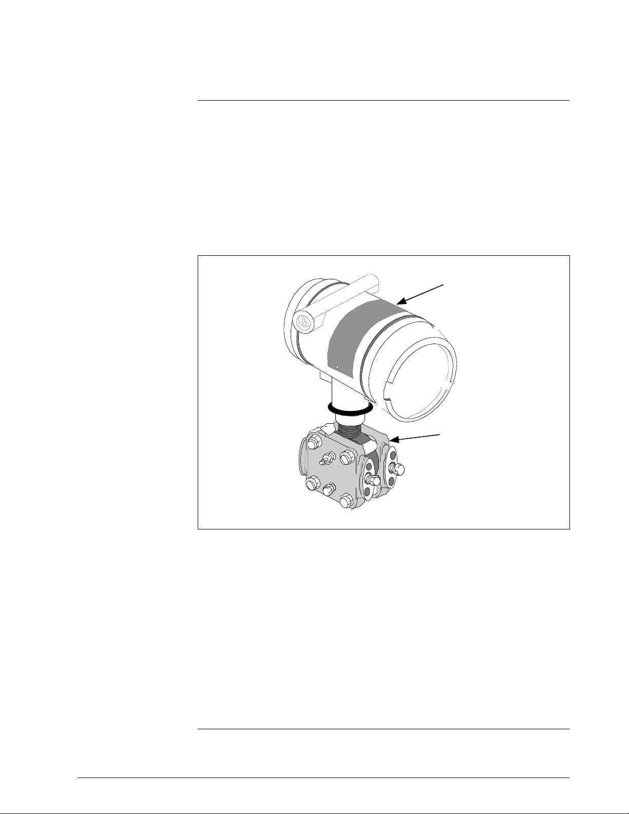
The SMV 3000 Smart Multivariable Transmitter shown in Figure 1
measures three separate process variables and calculates volumetric or
mass flow rate for gases, steam or liquids for output over a 4 to 20
milliampere, two-wire loop. Its general design is based on the field proven
technology of our ST 3000 Smart Pressure Transmitter and meets the
same high performance standards.
Figure 1 SMV 3000 Transmitter Handles Multiple Process Variable
Measurements and Calculates Flow Rate
Electronics
Housing
Meter body
The SMV 3000 transmitter accepts process temperature signals from an
external Resistance Temperature Detector (RTD) or any one of several
common thermocouple types. Its unique measurement sensor
simultaneously handles differential pressure, static pressure, and meter
body temperature signals while a separate circuit processes the process
temperature input. Note that the static pressure (absolute or gauge) is read
from the high pressure side of the meter body.
Using stored equations in conjunction with the multiple process variable
inputs, the SMV 3000 calculates a compensated volumetric or mass flow
rate output for gases, liquids and steam. Its output signal is proportional to
the calculated differential flow rate.
Continued on next page
1/99 SMV 3000 Transmitter User’s Manual 3
Page 16
1.3 SMV 3000 Smart Multivariable Transmitters, Continued
SMV Operating Modes
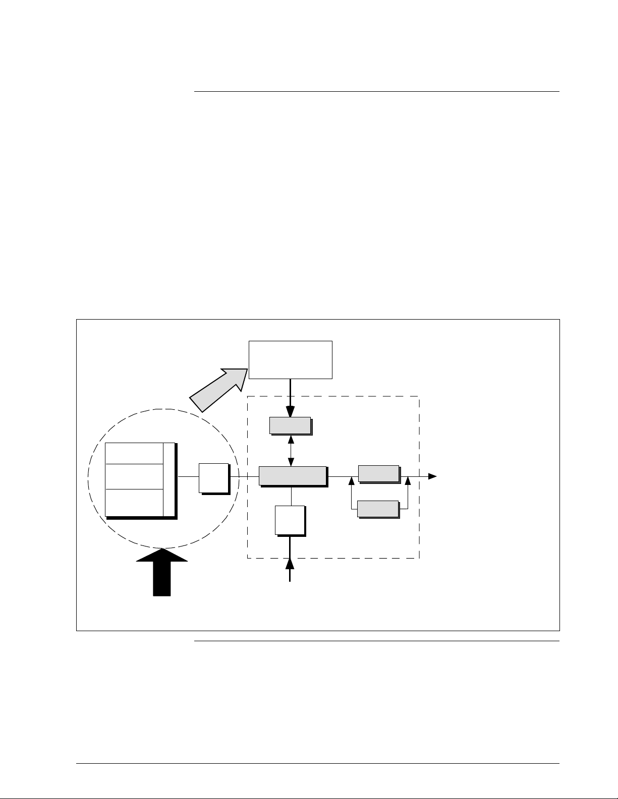
The SMV 3000 can transmit its output in either an analog 4 to 20
milliampere format or a Digitally Enhanced (DE) protocol format for
direct digital communications with our TPS/TDC 3000 control system. In
the analog format, only a selected variable is available as an output which
can be any one of the following:
• Differential Pressure PV1,
• Static Pressure PV2,
• Process Temperature PV3, or
• Calculated Flow Rate PV4
Note that the secondary variable is only available as a read only parameter
through the SCT or SFC. See Figure 2.
Figure 2 Functional Block Diagram for Transmitter in Analog Mode of Operation.
Factory
Characterization
Data
s
c
i
g
t
n
s
i
i
t
Meter Body
r
a
e
r
t
e
c
p
a
r
O
a
h
C
Electronics Housing
∆P Senso r
PV1
Temperature
Sensor
SV1
Static Pre ssure
Sensor
PV2
Pressure
PROM
r
e
x
e
l
p
i
t
l
u
M
A/D
Microprocessor
A/D
PV3
RTD or
PV4
D/A
Digital I/O
Proportional 4 to 20mA
output for selected PV
(Digital signal imposed
during SFC
communications).
PV1 = Differential Pressure
PV2 = Static Pressure
PV3 = Process Tem peratur e
PV4 = Calculated Volumetric
or Mass Flow
SV1 = Meter Body Temperature
(Read only)
Thermocouple
Input
Continued on next page
4 SMV 3000 Transmitter User’s Manual 1/99
Page 17
1.3 SMV 3000 Smart Multivariable Transmitters, Continued
SMV Operating
Modes, continued
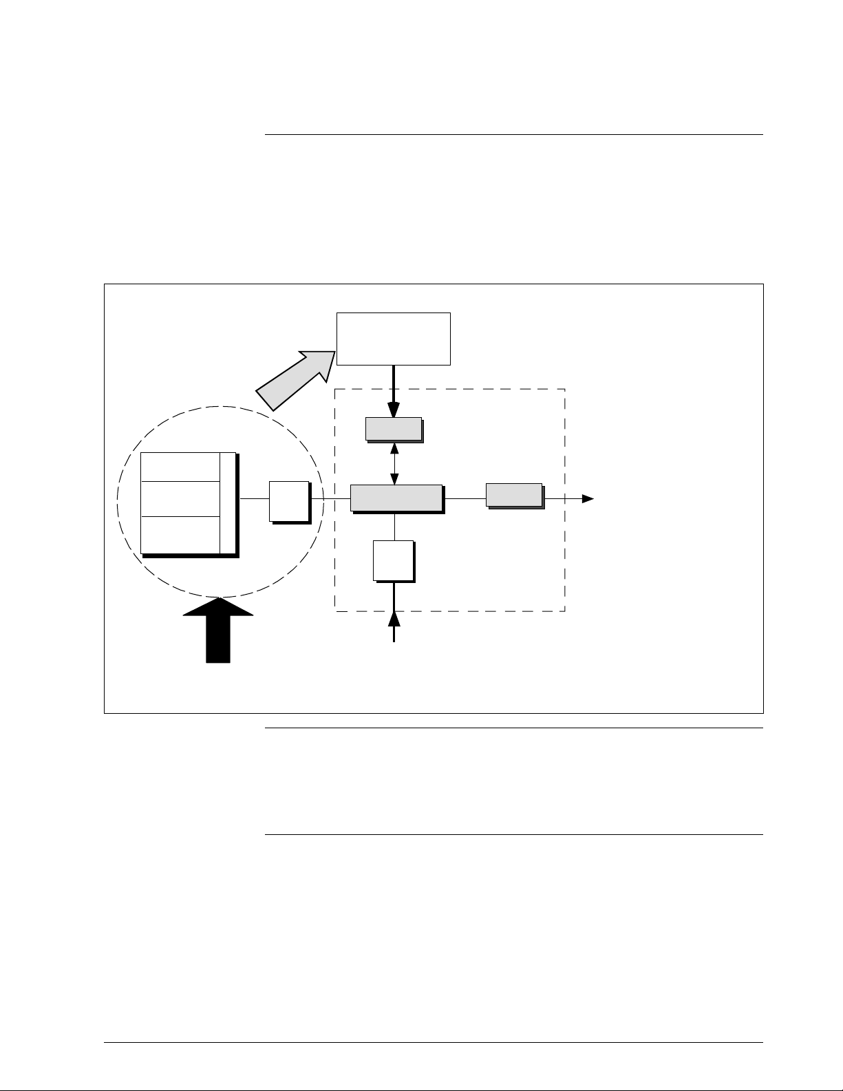
In the digital DE protocol format, all four process variables are available
for monitoring and control purposes; and the meter body temperature is
also available as a secondary variable for monitoring purposes only - See
Figure 3.
Figure 3 Functional Block Diagram for Transmitter in Digital DE Mode of Operation.
Factory
Characterization
Data
s
c
i
g
t
n
s
i
i
t
Meter Body
∆P Sensor
PV1
Temperature
Sensor
SV1
Static Pressure
Sensor
PV2
Pressure
r
a
e
r
t
e
c
p
a
r
O
a
h
C
PROM
r
e
x
e
l
p
i
t
l
u
M
A/D
Microprocessor
A/D
RTD or
Thermocouple
Input
Electr onics Housing
PV4
PV3
Digital I/O
Digital signal broa dcast s
up to 4 PVs plus
secondary variable i n
floating point format over
20mA loop.
PV1 = Differential Pr essure
PV2 = Static Pressure
PV3 = Process Temperature
PV4 = Calculated Volumetric
or Mass Flow
SV1 = Meter Body Temperature
(Monitoring purposes only)
Transmitter
adjustments
The SMV 3000 transmitter has no physical adjustments. You need an SCT
to make any adjustments in an SMV 3000 transmitter. Alternately, certain
adjustments can be made through the Universal Station if the transmitter is
digitally integrated with our TPS/TDC 3000 control system.
1/99 SMV 3000 Transmitter User’s Manual 5
Page 18
1.4 Smartline Configuration Toolkit (SCT 3000)
Smartline
Configuration Toolkit
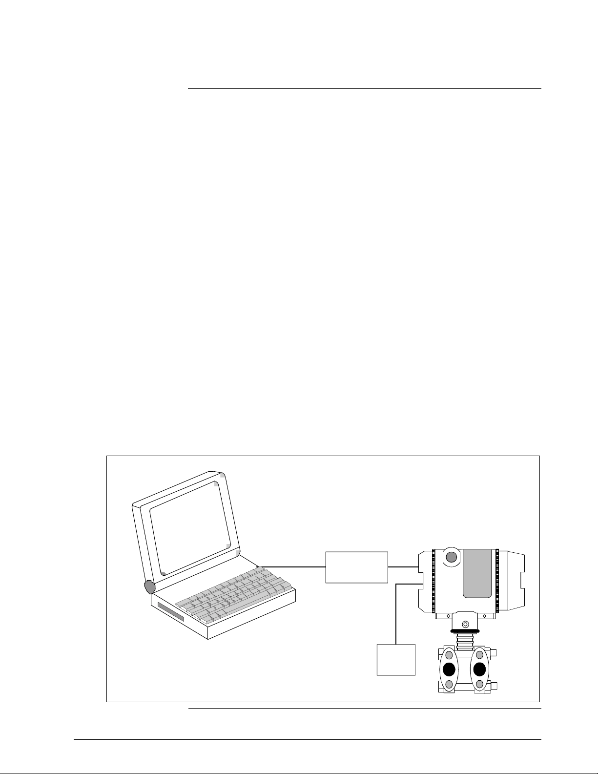
Honeywell’s SCT 3000 Smartline Configuration Toolkit is a cost-effective
means to configure, calibrate, diagnose, and monitor the SMV 3000 and
other smart field devices. The SCT 3000 runs on a variety of Personal
Computer (PC) platforms using Windows 95
. It is a bundled Microsoft Windows software and PC-interface
NT
Window 98 and Windows
hardware solution that allows quick, error-free configuration of SMV
transmitters. Figure 4 shows the major components of the SCT 3000.
Some SCT 3000 features include:
• Preconfigured templates that simplify configuration and allow rapid
development of configuration databases.
• Context-sensitive help and a comprehensive on-line user manual.
• Extensive menus and prompts that minimize the need for prior training
or experience.
• The ability to load previously configured databases at time of
installation.
• Automatic verification of device identification and database
configuration menus and prompts for bench set up and calibration.
• The ability to save unlimited transmitter databases on the PC.
Please refer to the table on Page 1 for SCT software versions that are
compatible with your SMV 3000 transmitter. Contact your Honeywell
representative for more information.
Figure 4 Smartline Configuration Toolkit
PC or Laptop running
SCT 3000 Software Program
SMV 3000
Smartline
Option Module
Power
Supply
6 SMV 3000 Transmitter User’s Manual 1/99
Page 19
1.5 Smart Field Communicator (SFC)
About SFC
Communications
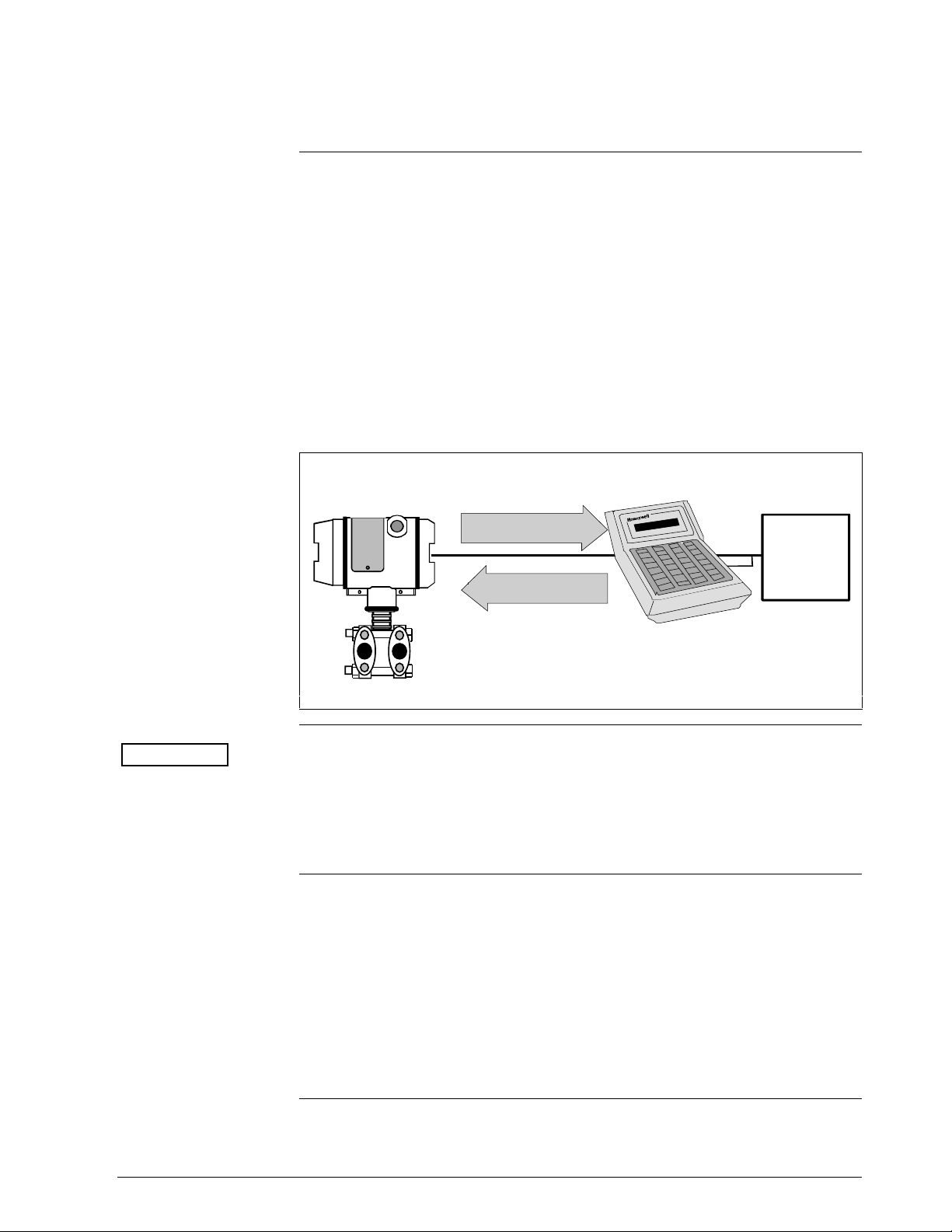
The portable, battery-powered SFC serves as the common communication
interface device for Honeywell’s family of Smartline Transmitters. It
communicates with a transmitter through serial digital signals over the 4 to
20 milliampere line used to power the transmitter. A request/response
format is the basis for the communication operation. The transmitter’s
microprocessor receives a communication signal from the SFC, identifies
the request, and sends a response message.
Figure 5 shows a simplified view of the communication interface provided
by an SFC.
Figure 5 Typical SFC Communication Interface
SMV 3000
Response
4 to 20 mA line
Request
SFC
Power
Supply and
Receiver
ATTENTION
Because of the advanced capabilities built-in to the SMV 3000, we do not
recommend that you use the SFC to configure the SMV transmitter. Some
of the SMV’s advance functions are not supported by the SFC. Although
you can use the SFC to perform certain operations, such as calibrate or rerange the transmitter, read transmitter status and diagnose faults.
Using the SFC with
the SMV 3000
If you use the SFC to communicate with the SMV, you can adjust
transmitter values, or diagnose potential problems from a remote location
such as the control room. You can use the SFC to:
• Monitor: Read the input pressure, process temperature, or
secondary variable to the transmitter in engineering
units.
• Display: Retrieve and display data from the transmitter or SFC
memory.
Continued on next page
1/99 SMV 3000 Transmitter User’s Manual 7
Page 20

1.5 Smart Field Communicator (SFC), Continued
Using the SFC with
the SMV 3000,
continued
ATTENTION
• Change Mode
of Operation: Tell transmitter to operate in either its analog (4-20
mA) mode or its digital enhanced (DE) mode.
• Check Current
Output: Use the transmitter to supply the output current desired
for verifying analog loop operation, troubleshooting, or
calibrating other components in the analog loop.
• Simulate
Input: Use the transmitter to simulate a desired input value for
the selected PV for verifying transmitter operation.
• Troubleshoot: Check status of transmitter operation and display
diagnostic messages to identify transmitter,
communication, or operator error problems.
For more information about using the SFC with the SMV 3000, see the
Smart Field Communicator Model STS103 Operating Guide,
34-ST-11-14. The document provides complete keystroke actions and
prompt displays.
Continued on next page
8 SMV 3000 Transmitter User’s Manual 1/99
Page 21
1.6 Transmitter Order
Order Components
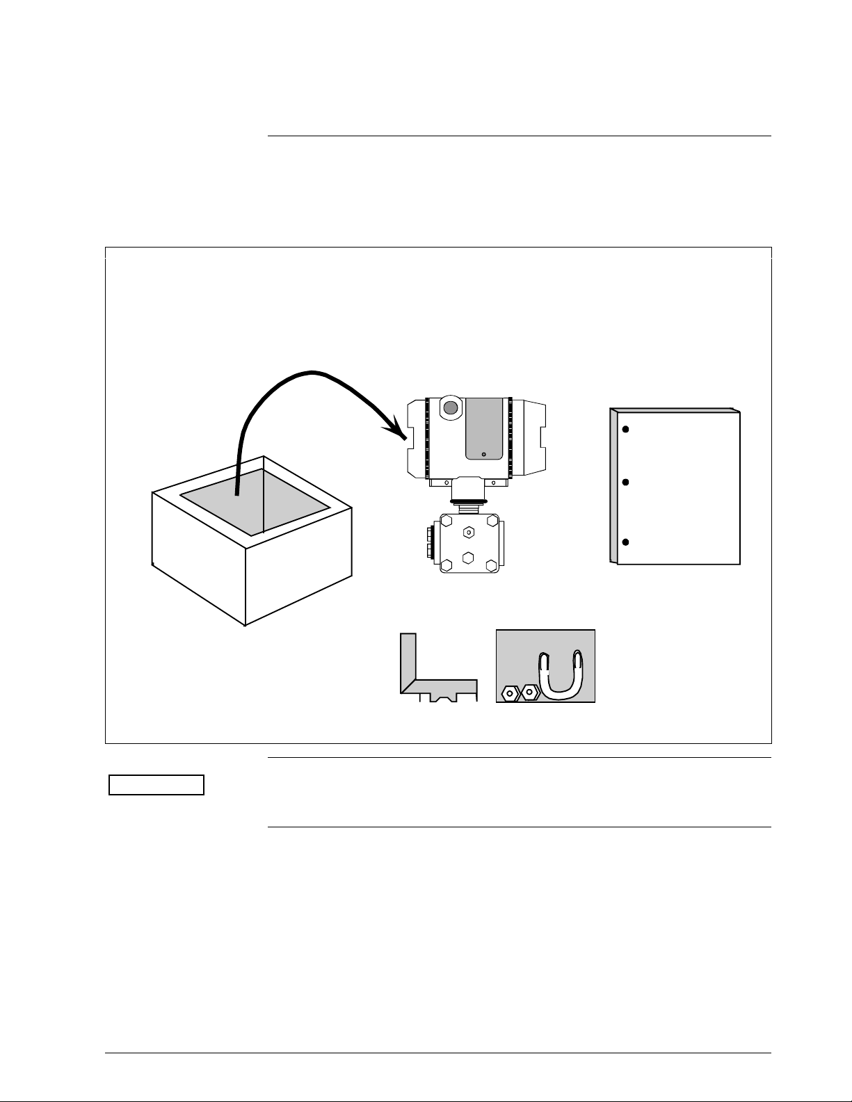
Figure 6 shows the components that would be shipped and received for a
typical SMV 3000 transmitter order.
Figure 6 Typical SMV 3000 Transmitter Order Components
Ordered
w SMV 3000 T ransmitter wi th optional mounting br acket
Shipped
Received
SMV 3000
User’s
Manual
ATTENTION
Mounting Bracket (Optional)
Honeywell can also supply the RTD or Thermocouple for use with an
SMV 3000. See “About Documentation,” next.
Continued on next page
1/99 SMV 3000 Transmitter User’s Manual 9
Page 22

1.6 Transmitter Order, Continued
About Documentation
• SCT 3000 Smartline Configuration Toolkit Start-up and Installation
Manual 34-ST-10-08: One copy supplied with the SCT 3000
Smartline Configuration Toolkit. This document provides basic
information on installation, setup and operation of the SCT 3000. It is
a companion document to the SCT on-line user manual.
• SMV 3000 Smart Multivariable Transmitter User’s Manual 34-SM-25-
02: One copy is shipped with every transmitter order up to five units.
Orders for more than five units will ship with one SMV user manual
for every five transmitters. This document provides detailed
information for installing, wiring, configuring, starting up, operating,
maintaining, and servicing the SMV 3000 transmitter. This is the main
reference manual for the SMV 3000 transmitter.
• Smart Field Communicator Model STS103 Operating Guide
34-ST-11-14: One copy is shipped with every SFC. This document
provides generic SFC information and detailed keystroke actions for
interfacing with these Honeywell Smartline Transmitters.
– SMV 3000 Smart Multivariable Transmitter
– ST 3000 Smart Pressure Transmitter
– STT 3000 Smart Temperature Transmitter
– MagneW 3000 Smart Electromagnetic Flowmeter
• Guide to Temperature Sensors and Thermowells, 34-44-29-01: This
document tells you how to properly specify thermal probes and
thermowell assemblies for your application. Model selection guides
also are included for various temperature probes.
10 SMV 3000 Transmitter User’s Manual 1/99
Page 23

Section 2 Quick Start Reference
2.1 Introduction
Section Contents
About this section
This section includes these topics
Topic See Page
2.1 Introduction............................................................................13
2.2 Getting SMV 3000 Transmitter On-Line Quickly.....................14
This section provides a list of typical start-up tasks and tells you where
you can find detailed information about performing the task.
This section assumes that the SMV 3000 transmitter has been installed
and wired correctly, and is ready to be put into operation. It also assumes
that you are somewhat familiar with using the SCT and that the transmitter
has been configured correctly for your application. If the transmitter has
not been installed and wired, you are not familiar with SCT operation,
and/or you do not know if the transmitter is configured correctly, please
read the other sections of this manual or refer to the SCT 3000 Smartline
Configuration Toolkit Start-up and Installation Manual (34-ST-10-08)
before starting up your transmitter.
1/99 SMV 3000 Transmitter User’s Manual 11
Page 24

2.2 Getting SMV 3000 Transmitter On-Line Quickly
Quick Start-up Tasks
Table 1 lists common start-up tasks for an SMV 3000 transmitter using the
SCT and gives an appropriate section in this manual to reference for more
information about how to do the task. The start-up tasks are listed in the
order they are commonly completed.
Table 1 Start-up Tasks Reference
Task Description Reference Section
Put analog loop into manual
1
mode.
Connect SCT to transmitter and
2
establish communications
Identify transmitter’s mode of
3
operation.
Change mode of operation, if
4
required.
Check/set output conformity
5
(Linear/Square Root) for PV1.
Appropriate vendor documentation
for controller or recorder used as a
receiver in analog loop with
SMV 3000 transmitter.
5.2
5.3
5.3
6.6
10
11
12
13
Check/set damping times for all
6
PVs.
Check/set Probe Configuration
7
for PV3
Check/set PV4 Algorithm 6.9, 6.10, 6.11
8
Check/set Lower Range Values
9
and Upper Range Values for all
PVs.
Select PV to represent output for
transmitter in analog mode only.
Run optional output check for
analog loop.
Perform start-up procedures Check zero input and set, if
required.
Check transmitter status, access
operating data.
6.6 (for PV1)
6.7 (for PV2)
6.8 (for PV3)
6.9 (for PV4)
6.8
6.6 (for PV1)
6.7 (for PV2)
6.8 (for PV3)
6.9 (for PV4)
6.5
7.3
7.5
8.2
12 SMV 3000 Transmitter User’s Manual 1/99
Page 25

Section 3 Preinstallation Considerations
3.1 Introduction
Section Contents
About this section
This section includes these topics
Topic See Page
3.1 Introduction............................................................................16
3.2 Considerations for SMV 3000 Transmitter..............................17
3.3 Considerations for SCT 3000.................................................21
This section reviews things you should take into consideration before you
install the transmitter and start using the SCT. Of course, if you are
replacing an existing SMV 3000 transmitter, you can skip this section.
1/99 SMV 3000 Transmitter User’s Manual 13
Page 26
3.2 Considerations for SMV 3000 Transmitter
Evaluate conditions
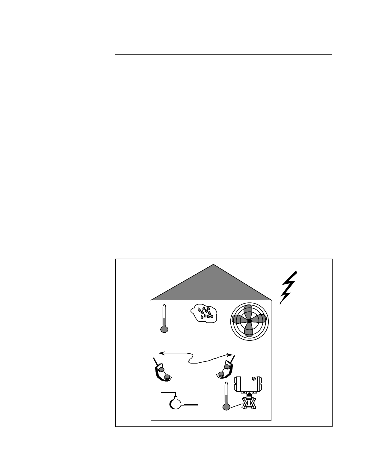
The SMV 3000 transmitter is designed to operate in common indoor
industrial environments as well as outdoors. To assure optimum
performance, evaluate these conditions at the mounting area relative to
published transmitter specifications and accepted installation practices for
electronic pressure transmitters.
• Environmental Conditions
– Ambient Temperature
– Relative Humidity
• Potential Noise Sources
– Radio Frequency Interference (RFI)
– Electromagnetic Interference (EMI)
• Vibration Sources
– Pumps
– Motorized Valves
– Valve Cavitation
• Process Characteristics
– Temperature
– Maximum Pressure Rating
Figure 7 illustrates typical mounting area considerations to make before
installing a transmitter.
Figure 7 Typical Mounting Area Considerations Prior to Installation
Lightning
(EMI)
Relative
Ambient
Temperature
Pump
(vibration)
Humidity
Transceivers
(RFI)
Large Fan Motors
(EMI)
Meter Body
Temperature
21003
Continued on next page
14 SMV 3000 Transmitter User’s Manual 1/99
Page 27

3.2 Considerations for SMV 3000 Transmitter, Continued
Temperature limits
Table 2 lists the operating temperature limits for reference.
Table 2 Operating Temperature Limits
Overpressure ratings
Transmitter Type Ambient
Temperature
Multivariable °C
°F
* For CTFE fill fluid, the rating is –15 to 110 °C (5 to 230 °F)
–40 to 93
–40 to 200
Table 3 lists overpressure rating for a given Upper Range Limit (URL) for
Meter Body
–40 to 125 *
–40 to 257 *
reference.
Table 3 Transmitter Overpressure Ratings
SMV 3000
Transmitter Model Upper Range Limit (URL) Overpressure Rating
SMA110
25 inches H2O @ 39.2
°F (differential pressure)
100 psi
100 psia (absolute pressure) * 100 psi
SMA125
SMG170
* Static pressure is referenced at high pressure port.
400 inches H2O @ 39.2
750 psia (absolute pressure) * 3000 psi
400 inches H2O @ 39.2
3000 psig (gauge pressure) 3000 psi
°F (differential pressure)
°F (differential pressure)
3000 psi
3000 psi
1/99 SMV 3000 Transmitter User’s Manual 15
Page 28

3.2 Considerations for SMV 3000 Transmitter, Continued
RTD requirements
Thermocouple
requirements
Use a two-, three-, or four-wire platinum 100 ohm (Pt100) Resistance
Temperature Detector with rated measurement range limits of –200 to
450 °C (–328 to 842 °F) per DIN 43760 standard (α = 0.00385 Ω/Ω/°C)
as the input source for the process temperature PV.
Use one of the thermocouple types listed in Table 4 as the input source for
the process temperature.
Table 4 Thermocouple Types for Process Temperature Sensor
Type Rated Range Limits Standard
°C °F
E
J
K
T
0 to 1000 32 to 1832 IEC584.1
0 to 1200 32 to 2192 IEC584.1
–100 to 1250 –148 to 2282 IEC584.1
–100 to 400 –148 to 752 IEC584.1
16 SMV 3000 Transmitter User’s Manual 1/99
Page 29

3.3 Considerations for SCT 3000
SCT 3000
Requirements
The SCT 3000 consists of the software program which is contained on
diskettes and a Smartline Option Module which is the hardware interface
used for connecting the host computer to the SMV transmitter.
Be certain that the host computer is loaded with the proper operating
system necessary to run the SCT program. See the SCT 3000 Smartline
Configuration Toolkit Start-up and Installation Manual 34-ST-10-08 for
complete details on the host computer specifications and requirements for
using the SCT 3000.
1/99 SMV 3000 Transmitter User’s Manual 17
Page 30

18 SMV 3000 Transmitter User’s Manual 1/99
Page 31

4.1 Introduction
Section 4 Installation
Section Contents
About this section
This section includes these topics
Topic See Page
4.1 Introduction............................................................................19
4.2 Mounting SMV 3000 Transmitter............................................20
4.3 Piping SMV 3000 Transmitter.................................................29
4.4 Installing RTD or Thermocouple.............................................35
4.5 Wiring SMV 3000 Transmitter................................................36
This section provides information about installing the SMV 3000
transmitter. It includes procedures for mounting, piping and wiring the
transmitter for operation.
1/99 SMV 3000 Transmitter User’s Manual 19
Page 32

4.2 Mounting SMV 3000 Transmitter
Summary
You can mount the transmitter to a 2-inch (50 millimeter) vertical or
horizontal pipe using our optional angle or flat mounting bracket or a
bracket of your own.
Figure 8 shows typical bracket mounted installations for comparison.
Figure 8 Typical Bracket Mounted Installations
Angle
Mounting
Bracket
Flat
Mounting
Bracket
Dimensions
Horizontal Pipe
Angle
Mounting
Bracket
Vertical Pipe
Flat
Mounting
Bracket
Detailed dimension drawings for given mounting bracket type are listed in
the back of this manual for reference. This section assumes that the
mounting dimensions have already been taken into account and the
mounting area can accommodate the transmitter.
Continued on next page
20 SMV 3000 Transmitter User’s Manual 1/99
Page 33

4.2 Mounting SMV 3000 Transmitter, Continued
Bracket mounting
Table 5 summarizes typical steps for mounting a transmitter to a bracket.
Table 5 Mounting SMV 3000 Transmitter to a Bracket
Step Action
1
If you are using an… Then…
optional mounting bracket go to Step 2.
existing mounting bracket go to Step 3.
Position bracket on 2-inch (50.8 mm) horizontal or vertical pipe, and
2
install “U” bolt around pipe and through holes in bracket. Secure with
nuts and lockwashers provided.
Example - Angle mounting bracket secured to horizontal or vertical
pipe.
Nut s and
Lockwashers
Mounting
Bracket
Nuts and
Lockwashers
Horizontal Pipe
U-Bolt
U-Bolt
Vertical Pipe
Mounting
Bracket
Continued on next page
1/99 SMV 3000 Transmitter User’s Manual 21
Page 34

4.2 Mounting SMV 3000 Transmitter, Continued
Bracket mounting,
continued
Table 5 Mounting SMV 3000 Transmitter to a Bracket, continued
Step Action
Align alternate mounting holes in end of meter body heads with holes
3
in bracket and secure with bolts and washers provided.
Loosen the 4 mm set screw on outside neck of transmitter. Rotate
4
electronics housing in maximum of 90 degree increments in left or
right direction from center to position you require and tighten set
screw.
Example - Rotating electronics housing.
90 degrees
max.
Electronics
Housing
90 degrees
max.
Set Screw
Continued on next page
22 SMV 3000 Transmitter User’s Manual 1/99
Page 35

4.2 Mounting SMV 3000 Transmitter, Continued
ATTENTION
Precautions for
Mounting
Transmitters with
Small Differential
Pressure Spans
The mounting position of an SMV 3000 Transmitter is critical as the
transmitter spans become smaller for the absolute and/or differential
pressure range. A maximum zero shift of 0.048 psi for an absolute
pressure range or 1.5 in H
O for a differential pressure range can result
2
from a mounting position which is rotated 90 degrees from vertical. A
typical zero shift of 0.002 psi or 0.20 in H
O can occur for a 5 degree
2
rotation from vertical.
To minimize these positional effects on calibration (zero shift), take the
appropriate mounting precautions that follow for the given pressure range.
• For a transmitter with a small differential pressure span, you must
ensure that the transmitter is vertical when mounting it. You do this by
leveling the transmitter side-to-side and front-to-back. See Figure 9 for
suggestions on how to level the transmitter using a spirit balance.
• You must also zero the transmitter by adjusting the mounting position
of the transmitter. Refer to start-up procedure in Section 7 for SMV
3000 transmitter model SMA110 and transmitters with small
differential pressure spans.
Figure 9 Leveling a Transmitter with a Small Absolute Pressure Span.
Spirit
Balance
1/99 SMV 3000 Transmitter User’s Manual 23
Process
Head
Center
Section
Page 36

4.3 Piping SMV 3000 Transmitter
Summary
The actual piping arrangement will vary depending upon the process
measurement requirements. Process connections can be made to standard
1/4-inch NPT female connections on 2-1/8 inch centers in the doubleended process heads of the transmitter’s meter body. Or, the connections
in the process heads can be modified to accept 1/2 inch NPT adapter
flange for manifolds on 2, 2-1/8, or 2-1/4 inch centers
The most common type of pipe used is 1/2 inch schedule 40 steel pipe.
Many piping arrangements use a three-valve manifold to connect the
process piping to the transmitter. A manifold makes it easy to install and
remove a transmitter without interrupting the process. It also
accommodates the installation of blow-down valves to clear debris from
pressure lines to the transmitter.
Figure 10 shows a diagram of a typical piping arrangement using a threevalve manifold and blow-down lines for a flow measurement application.
Figure 10 Typical 3-Valve Manifold and Blow-Down Piping
Arrangement.
To Upstream TapTo Downstream Tap
Blow-Down
Valve
Blow-Down
Piping
To Low Pressure
Side of Transmitter
24 SMV 3000 Transmitter User’s Manual 1/99
3-Valve
Manifold
To High Pressure
Side of Transmitter
Blow-Down
Valve
Blow-Down
Piping
To WasteTo Waste
21010
Continued on next page
Page 37

4.3 Piping SMV 3000 Transmitter, Continued
Transmitter location
The suggested mounting location for the transmitter depends on the
process to be measured. Figure 11 shows the transmitter located above the
tap for gas flow measurement. This arrangement allows for condensate to
drain away from the transmitter.
Figure 12 shows the transmitter located below the tap for liquid or steam
flow measurement. This arrangement minimizes the static head effect of
the condensate. Although the transmitter can be located level with or
above the tap, this arrangement requires a siphon to protect the transmitter
from process steam. (The siphon retains water as a “fill fluid.”)
Figure 11 Transmitter Location Above Tap for Gas Flow Measurement
High
Pressure
Connection
Low
Pressure
Connection
3-Valve
Manifold
Pressure
Connection
To High
To Low
Pressure
Connection
Continued on next page
1/99 SMV 3000 Transmitter User’s Manual 25
Page 38

4.3 Piping SMV 3000 Transmitter, Continued
Figure 12 Transmitter Location Below the Tap for Liquid or Steam
Flow Measurement
High
Pressure
Connection
3-Valve
Manifold
To High
Pressure
Connection
Low
Pressure
Connection
To Low
Pressure
Connection
ATTENTION
For liquid or steam, the piping should slope a minimum of 25.4 mm (1
inch) per 305 mm (1 foot). Slope the piping down towards the transmitter
if the transmitter is below the process connection so the bubbles may rise
back into the piping through the liquid. If the transmitter is located above
the process connection, the piping should rise vertically above the
transmitter; then slope down towards the flow line with a vent valve at the
high point. For gas measurement, use a condensate leg and drain at the
low point (freeze protection may be required here).
Continued on next page
26 SMV 3000 Transmitter User’s Manual 1/99
Page 39

4.3 Piping SMV 3000 Transmitter, Continued
General piping
guidelines
Installing flange
adapter
ATTENTION
• When measuring fluids containing suspended solids, install permanent
valves at regular intervals to blow-down piping.
• Blow-down all lines on new installations with compressed air or steam
and flush them with process fluids (where possible) before connecting
these lines to the transmitter’s meter body.
• Be sure all the valves in the blow-down lines are closed tight after the
initial blow-down procedure and each maintenance procedure after that.
Table 6 gives the steps for installing an optional 1/2 inch NPT flange
adapter on the process head.
Slightly deforming the gasket supplied with the adapter before you insert it
into the adapter may aid in retaining the gasket in the groove while you
align the adapter to the process head. To deform the gasket, submerse it in
hot water for a few minutes then firmly press it into its recessed mounting
groove in the adapter.
Continued on next page
1/99 SMV 3000 Transmitter User’s Manual 27
Page 40

4.3 Piping SMV 3000 Transmitter, Continued
Installing flange
adapter, continued
Table 6 Installing 1/2 inch NPT Flange Adapter
Step Action
Insert filter screen (if supplied) into inlet cavity of process head.
1
Carefully seat Teflon (white) gasket into adapter groove.
2
Thread adapter onto 1/2-inch process pipe and align mounting holes
3
in adapter with holes in end of process head as required.
Secure adapter to process head by hand tightening 7/16-20 hex-head
4
bolts.
Example - Installing adapter on process head.
Filter Screen
Teflon Gasket
Flange Adapter
7/16 x 20 Bolts
ATTENTION
Apply an anti-seize compound on the stainless steel
bolts prior to threading them into the process head.
5
Evenly tighten adapter bolts to a torque of 47.5 to 54 N.m
(35 to 40 ft-lb).
Process
Hea d
21011
28 SMV 3000 Transmitter User’s Manual 1/99
Page 41

4.4 Installing RTD or Thermocouple
Considerations
CE Conformity
Special Conditions
(Europe)
You are responsible for installing the thermowell to house the RTD or
thermocouple sensor. Be sure to use a spring-load accessory to hold the
RTD sensor against the end of the thermowell.
To reduce the effects of “noise,” use shielded cable or run sensor leads in
a conduit.
See the Guide to Temperature Sensors and Thermowells, 34-44-29-01
which tells you how to properly specify thermal probes and thermowell
assemblies for your application. Model selection guides also are included
for various temperature probes.
You must use shielded cable to connect sensor to transmitter’s
temperature circuit.
1/99 SMV 3000 Transmitter User’s Manual 29
Page 42

4.5 Wiring SMV 3000 Transmitter
CE Conformity Special
Conditions (Europe)
Summary
You must use shielded, twisted-pair cable such as Belden 9318 for all
signal/power wiring.
The transmitter is designed to operate in a two-wire power/current loop
with loop resistance and power supply voltage within the operating range
shown in Figure 13.
Figure 13 Operating Range for SMV 3000 Transmitters
1440
Loop
Resistance
(ohms)
1200
800
650
450
250
= Operating
Area
NOTE: A minimum of 250
0hms of loop resistance is
necessary to support
communications. Loop
resistance equals barrier
resistance plus wire
resistance plus receiver
resistance. Also 45 volt
operation is permitted if
not an intrinsically safe
installation.
0 10.8 16.28 20.63 25 28.3 37.0 42.4
Operating Voltage (Vdc)
21012
You simply connect the positive (+) and negative (–) loop wires to the
positive (+) and negative (–) SIGNAL terminals on the terminal block in
the transmitter’s electronics housing shown in Figure 14.
Continued on next page
30 SMV 3000 Transmitter User’s Manual 1/99
Page 43

4.5 Wiring SMV 3000 Transmitter, Continued
Figure 14 SMV 3000 Transmitter Terminal Block
TC
34
++
+
–
+
–
Terminal
Block
Electronics
Housing
12
METER L SIGNAL
–––
TEST SIG
Summary, continued
You connect RTD leads to the TC terminals 1, 2, 3, and 4 as appropriate
for the given probe type.
You connect thermocouple leads to terminals 1 (–) and 3 (+), observing
polarity.
Each transmitter includes an internal ground terminal to connect the
transmitter to earth ground or a ground terminal can be optionally added to
the outside of the electronics housing. While it is not necessary to ground
the transmitter for proper operation, we suggest that you do so to minimize
the possible effects of “noise” on the output signal and provide additional
protection against lightning and static discharge damage. Note that
grounding may be required to meet optional approval body certification.
Refer to section 1.2 CE Conformity (Europe) Notice for special
conditions.
Transmitters are available with optional lightning protection if they will be
used in areas highly susceptible to lightning strikes.
Barriers must be installed per manufacturer’s instructions for transmitters
to be used in intrinsically safe installations (see control drawing 51404251
in Section 13 for additional information).
Continued on next page
1/99 SMV 3000 Transmitter User’s Manual 31
Page 44

4.5 Wiring SMV 3000 Transmitter, Continued
TPS/TDC 3000
reference
Optional meter
Transmitters that are to be digitally integrated to our TPS/TDC 3000
systems will be connected to the Smart Transmitter Interface
Multivariable Module in the Process Manager, Advanced Process
Manager, or High Performance Process Manager through a Field
Termination Assembly. Details about the TPS/TDC 3000 system
connections are given in the PM/APM Smartline Transmitter Integration
Manual PM12-410 which is part of the TPS/TDC 30000 system bookset
and in Appendix A of this manual.
The SMV 3000 transmitter can be equipped with an optional analog
output meter.
The analog meter provides a 0 to 100% indication of the transmitter’s
output through traditional pointer and scale indication. It can be mounted
integrally on top of the terminal block in the electronics housing with a
meter end cap or remotely in a separate housing.
You connect the analog meter across the meter terminals on the terminal
block with the metal jumper strap removed. For more detailed information
on wiring the analog meter, refer to control drawing 51404251 (for
intrinsically safe installations) and external wiring diagrams 51404250 and
51404251 (for non-intrinsically safe installations) in Section 13.
Wiring connections
ATTENTION
The procedure in Table 7 shows the steps for connecting power/loop and
temperature sensor input wiring to the transmitter. For loop wiring
connections, refer to the control drawing 51404251 for intrinsically safe
loops and external wiring diagrams 51404250 and 51404251 for nonintrinsically safe loops in Section 13 for details. If you are using the SMV
transmitter with our TPS/TDC 3000 control systems, refer to the
appropriate TPS/TDC 3000 manual or Appendix A in this manual.
All wiring must be installed in accordance with the National Electrical
Code (ANSI/NFPA 70) and local codes and regulations.
Table 7 Wiring the Transmitter
Step Action
1
Loosen end-cap lock and remove electronic housing end-cap cover.
2
If transmitter is supplied with an optional integral meter, unsnap meter
from terminal block to expose wiring connections.
Continued on next page
32 SMV 3000 Transmitter User’s Manual 1/99
Page 45

4.5 Wiring SMV 3000 Transmitter, Continued
Wiring connections,
continued
Table 7 Wiring the Transmitter, Continued
Step Action
3
Feed temperature sensor input leads through conduit entrance in
housing. Strip 1/4 inch (6.35 mm) of insulation from input leads.
If input is from … Then…
2-wire RTD connect RTD leads to
terminals 1 and 3.
See Figure 15.
3-wire RTD connect RTD leads to
terminals 1, 2, and 3.
See Figure 15.
4-wire RTD connect RTD leads to
terminals 1, 2, 3, and 4. See
Figure 16.
2-wire Thermocouple connect minus (–) lead to
terminal 1 and plus (+) lead to
terminal 3. See Figure 16.
4
Feed loop power leads through conduit entrance on other side of
electronics housing opposite RTD wiring entrance.
ATTENTION
The transmitter accepts up to 16 AWG (1.5 mm
diameter) wire.
5
Strip 1/4 inch (6.35 mm) of insulation from leads. Observing polarity,
connect positive loop power lead to SIGNAL + terminal and negative
loop power lead to SIGNAL – terminal.
Example - Connecting loop power to transmitter.
_
+
TC
12
METER L SIGNAL
–––
6
If you have an optional analog meter, be sure jumper strap is removed
34
++
+
–
TEST SIG
+
–
from across METER terminals, yellow lead from meter is connected to
METER – terminal and red lead is connected to METER + terminal.
See control drawing 51404251 (for intrinsically safe installations) or
wiring diagram 51404250 (non-intrinsically safe) included in Section 13.
Loop
Power
Continued on next page
1/99 SMV 3000 Transmitter User’s Manual 33
Page 46

4.5 Wiring SMV 3000 Transmitter, Continued
Wiring connections,
continued
Figure 15 RTD Input Wiring Connections.
Table 7 Wiring the Transmitter, Continued
Step Action
7
Replace integral meter, if applicable; replace end-cap, and tighten
end-cap lock.
Legend:
R = Red
W = White
RTD
Keep Resistance
of All Leads Low
TC
12
METER L SIGNAL
–––
34
++
+
–
TEST SIG
+
–
R RWR RRWW
12
METER L SIGNAL
–––
TEST SIG
Keep Resistance
of All Leads Equal
TC
34
++
+–+
–
W
TC
12
METER L SIGNAL
–––
34
++
+
–
TEST SIG
+
–
2-Wire RTD Connections 3-Wire RTD Connections 4-Wire RTD Connections
Figure 16 Thermocouple Input Wiring Connections.
—
+
TC
34
12
METER L SIGNAL
++
–––
ATTENTION: If you use shielded
cable, be sure the shield and
transmitter housing reference
+
–
TEST SIG
–
+
ground at the same point.
Thermocouple Connections
Continued on next page
34 SMV 3000 Transmitter User’s Manual 1/99
Page 47

4.5 Wiring SMV 3000 Transmitter, Continued
Lightning protection
When your transmitter is equipped with optional lightning protection, you
must connect a wire from the transmitter to ground as shown in Figure 17
to make the protection effective. We recommend that you use a size 8
AWG (American Wire Gauge) or KCM (Kilo Circular Mils) bare or
Green covered wire.
Note that protection for temperature sensor leads is not provided by the
optional lightning protection.
Figure 17 Ground Connection for Lightning Protection
Electronics
Housing
Connect to
Earth Ground
1/99 SMV 3000 Transmitter User’s Manual 35
Page 48

4.5 Wiring SMV 3000 Transmitter, Continued
Conduit seals and
Hazardous Location
Installations
WARNING
Transmitters installed as explosionproof in a Class I, Division 1, Group A
Hazardous (Classified) Location in accordance with ANSI/NFPA 70, the
US National Electrical Code (NEC), require a “LISTED” explosionproof
seal to be installed in the conduit, within 18 inches of the transmitter.
Crouse-Hinds® type EYS/EYD or EYSX/EYDX are examples of
“LISTED” explosionproof seals that meets this requirement.
Transmitters installed as explosionproof in a Class I, Division 1, Group B,
C or D Hazardous (Classified) Locations do not require an explosionproof
seal to be installed in the conduit.
NOTE: Installation should conform to all national and local electrical
code requirements.
When installed as explosionproof in a Division 1 Hazardous Location,
keep covers tight while the transmitter is energized. Disconnect power to
the transmitter in the non-hazardous area prior to removing end caps for
service.
When installed as nonincendive equipment in a Division 2 Hazardous
Location, disconnect power to the transmitter in the non-hazardous area,
or determine that the location is non-hazardous prior to disconnecting or
connecting the transmitter wires.
36 SMV 3000 Transmitter User’s Manual 1/99
Page 49

Section 5 Getting Started
5.1 Introduction
Section Contents
About This Section
ATTENTION
This section includes these topics
Topic See Page
5.1 Introduction............................................................................37
5.2 Establishing Communications ................................................38
5.3 Making Initial Checks .............................................................42
5.4 Write Protect Option...............................................................43
If you have never used an SCT to “talk” to an SMV 3000 transmitter, this
section tells you how to connect the SMV with the SCT, establish on-line
communications and make initial checks.
The SCT 3000 contains on-line help and an on-line user manual providing
complete instructions for using the SCT to setup and configure SMV
transmitters.
1/99 SMV 3000 Transmitter User’s Manual 37
Page 50

5.2 Establishing Communications
Off-line Versus Online SMV
Configuration
Off-line Configuration
Procedures
SCT Hardware
Connections
The SCT 3000 allows you to perform both off-line and on-line
configuration of SMV transmitters.
• Off-line configuration does not require connection to the transmitter.
By operating the SCT 3000 in the off-line mode, you can configure
database files of an unlimited number of transmitters prior to receipt,
save them either to hard disk or a floppy diskette, and then download
the database files to the transmitters during commissioning.
• An on-line session requires that the SCT is connected to the transmitter
and allows you to download previously-configured database files at
any time during installation or commissioning of your field
application. Note that you can also upload a transmitter’s existing
configuration and then make changes directly to that database.
Refer to the SCT User Manual (on-line) for detailed procedures on how to
off-line configure SMV transmitters using the SCT 3000.
A PC or laptop computer (host computer) which contains the SCT
software program, is connected to the wiring terminals of the SMV
transmitter and other smart field devices. Figure 18 shows the hardware
components of the SCT.
Figure 18 SCT Hardware Components
SCT Software Program running
on Windows 95, Windows 98 or
Windows NT Operating System
PC Card
Line Interface
Commerically-available
Laptop or Desktop PC
SMARTLINE OPTION MODULE
Module
250 Ω
SMV 3000
Power
Supply
P
R
O
C
E
S
S
23057
Continued on next page
38 SMV 3000 Transmitter User’s Manual 1/99
Page 51

5.2 Establishing Communications, Continued
ATTENTION
SCT 3000 On-line
Connections to the
SMV
WARNING
Connecting the host computer to an SMV for on-line communications
requires Smartline Option Module consisting of a PC Card and Line
Interface Module.
Table 8 provides the steps to connect the assembled SCT 3000 hardware
between the host computer and the SMV for on-line communications.
When the transmitter’s end-cap is removed, the housing is not
explosionproof.
Table 8 Making SCT 3000 Hardware Connections
Step Action
1
With the power to the host computer turned off, insert the PC Card into
the type II PCMCIA slot on the host computer (see Figure 5-1).
ATTENTION To use the SCT 3000 in a desktop computer without a
PCMCIA slot, you must install a user-supplied
PCMCIA host adapter. Honeywell has performancequalified the following PCMCIA host adapters for use
with the SCT:
-- TMB-240 Single Slot Internal Front Panel Adapter
-- TMB-250 Dual Slot Internal Front Panel Adapter
-- GS-120 Greystone Peripherals, Inc.
-- GS-320 Greystone Peripherals, Inc.
CAUTION Do not insert a PC Card into a host computer’s
PCMCIA slot while the host computer is powered on.
2
1/99 SMV 3000 Transmitter User’s Manual 39
Remove the end-cap at the terminal block side of the SMV and connect
the easy hooks or alligator clips at the end of the adapter cable to the
respective terminals on the SMV as follows:
• Connect the red lead to the positive terminal.
• Connect the black lead to the negative terminal.
ATTENTION The SCT 3000 can be connected to only one
at a time.
Continued on next page
SMV
Page 52

5.2 Establishing Communications, Continued
Establishing On-line
Communications with
the SMV
Table 9 Making SCT 3000 On-line Connections
Table 9 lists the steps to begin an on-line session with the loop-connected
SMV and upload the database configuration from the transmitter.
Step Action
1
2
3 Perform either step 4A (recommended) or 4B (but not both) to upload
4A
Make sure that 24V dc power is applied to the proper SMV transmitter
SIGNAL terminals. See Subsection 4.5, Wiring SMV 3000 Transmitter
for details.
Apply power to the PC or laptop computer and start the SCT 3000
application.
the current database configuration from the SMV.
• Select Tag ID from the View Menu (or click on the Tag ID toolbar
button) to access the View Tag dialog box.
-- If the SCT 3000 detects that the transmitter is in analog mode,
a dialog box displays prompting you to put the loop in
manual and to check that all trips are secured (if necessary)
before continuing. Click OK to continue.
-- After several seconds, the SCT 3000 reads the device’s tag
ID and displays it in the View Tag dialog box.
• Click on the Upload button in the View Tag dialog box to upload
the current database configuration from the SMV and make the online connection.
-- A Communications Status dialog box displays during the
uploading process.
4B Select Upload from the Device Menu (or click on the Upload toolbar
button) to upload the current database configuration from the SMV and
make the on-line connection.
-- If the SCT 3000 detects that the transmitter is in analog mode,
a dialog box displays prompting you to put the loop in
manual and to check that all trips are secured (if necessary)
before continuing. Click OK to continue.
-- A Communications Status dialog box displays during the
uploading process.
Continued on next page
40 SMV 3000 Transmitter User’s Manual 1/99
Page 53

5.2 Establishing Communications, Continued
Making On-line
Connections to the
SMV, continued
Table 9 Making SCT 3000 On-line Connections, Continued
Step Action
5
6 Refer to the SCT 3000 User Manual (on-line) for a procedure on how
When the on-line view of the SMV appears on the screen, access the
Status form by clicking on its tab. The Status form is used to verify the
status of the connected field device.
• Separate list boxes for Gross Status and Detailed Status are
presented in the Status form. Refer to the SCT 3000 User
Manual (on-line) for explanations of each status condition.
to download any previously-saved configuration database files.
1/99 SMV 3000 Transmitter User’s Manual 41
Page 54

5.3 Making Initial Checks
Checking
Communication Mode
and Firmware Version
DE Communication
Mode
Changing
Communication Mode
Before doing anything else, it is a good idea to confirm the transmitter’s
mode of operation and identify the version of firmware being used in the
transmitter.
• Communication mode (either ANALOG or DE mode) is displayed on
the Status Bar at the bottom SCT application window.
• The transmitter’s firmware version is displayed on the Device
configuration form.
A transmitter in the digital (DE) mode can communicate in a direct digital
fashion with a Universal Station in Honeywell’s TPS and TDC 3000
control systems. The digital signal can include all four transmitter process
variables and its secondary variable as well as the configuration database.
You can select the mode you want the transmitter to communicate with
the control system. The communication mode is selected in the SCT
General Configuration form tab card.
42 SMV 3000 Transmitter User’s Manual 1/99
Page 55

5.4 Write Protect Option
Write Protect Option
The SMV 3000 transmitters are available with a “write protect option”. It
consists of a jumper located on the transmitter’s Main Printed Circuit
Board (PCB) under the temperature measurement (Daughter) PCB that
you can position to allow read and write access or read only access to the
transmitter’s configuration database. When the jumper is in the read only
position, you can only read/view the transmitter’s configuration and
calibration data. Note that the factory default jumper position is for read
and write access. There is no need to check jumper position unless you
want to change it.
Figure 19 shows the location of the write protect jumper on the electronics
module for SMV 3000 transmitters.
Figure 19 Write Protect Jumper Location and Selections with Daughter PCB Removed.
Main PWA
Flex Tape
Connector
Screw
Plastic
Bracket
Power
Connector
PWA
Connector
PROM
Location
Write
Protect
Jumper
Read
Write
W
R
and
Read
Only
PWA
Connector
Screw
Daughter PWA
Temperature
Input
Connector
Screw
1/99 SMV 3000 Transmitter User’s Manual 43
Page 56

44 SMV 3000 Transmitter User’s Manual 1/99
Page 57

Section 6 Configuration
6.1 Introduction
Section Contents
This section includes these topics
Topic See Page
6.1 Introduction ............................................................................45
6.2 Overview................................................................................47
6.3 Configuring the SMV 3000 with The SCT...............................49
6.4 Device Configuration ............................................................50
6.5 General Configuration ..........................................................51
6.6 DPConf Configuration - PV1.................................................54
6.7 AP/GPConf Configuration - PV2...........................................59
6.8 TempConf Configuration - PV3 ............................................61
6.9 FlowConf Configuration - PV4..............................................68
6.10 Flow Compensation Wizard....................................................74
6.11 Using Custom Engineering Units............................................75
6.12 Saving, Downloading and Printing a Configuration
File.........................................................................................77
6.13 Verifying Flow Configuration ..................................................78
About This Section
This section introduces you to SMV 3000 transmitter configuration. It
identifies the parameters that make up the transmitter’s configuration
database and provides information for entering values/selections for the
given configuration parameters using the SCT.
Continued on next page
1/99 SMV 3000 Transmitter User’s Manual 45
Page 58

6.1 Introduction, Continued
ATTENTION
SCT On-line Help and
User Manuals
Please verify that you have the SCT software version that is compatible
with your SMV 3000. Refer to the table on Page 1.
To check the software version, connect an SFC or SCT to the transmitter,
(see Figure 28 for typical SFC and SCT connections).
Using the SCT: Perform Upload of the SMV database to the SCT. The
SMV firmware version can be read from the Device tab
card.
To check the SCT software version, select About SCT
from the Help pull down menu. The software version
will be displayed.
Using the SFC: Press
SHIFT and ID keys. Wait for upload of transmitter
configuration to SFC.
Then press
SHIFT and 3. The software version for the
SFC and SMV will be displayed.
IMPORTANT: While the information presented in this section refers to
SMV 3000 transmitter configuration using the SCT 3000
software program, the SCT on-line manual and help
topics contain complete information and procedures on
SMV 3000 configuration and should be followed to
properly configure the transmitter.
To Print On-line
Manual and Help
Topics
This section of the manual should be viewed as
subordinate to the SCT on-line manual and if
inconsistencies exist between the two sources, the SCT
on-line manual will prevail.
Supplemental reference information is presented in this
section.
The sections of the SCT on-line manual and help topics can be printed out
for your reference.
1. Select
Contents or User Manual from the Help pull down menu of the
SCT application window.
2. Go to the
Contents tab.
3. Select a section or topic you wish to print out.
4. Click on the
SMV 3000 Transmitter User’s Manual 1/9946
Print . . . button.
Page 59

6.2 Overview
About Configuration
Each SMV 3000 Transmitter includes a configuration database that
defines its particular operating characteristics. You use the SCT 3000 to
enter and change selected parameters within a given transmitter’s database
to alter its operating characteristics. We call this process of viewing and/or
changing database parameters “configuration”.
SMV configuration can be done using the SCT either on-line, where
configuration parameters are written to the SMV through a direct
connection with the SCT, or off-line where the transmitter configuration
database is created and saved to disk for later downloading to the SMV.
Figure 20 shows a graphic summary of the on-line configuration process.
Figure 20 SMV On-line Configuration Process
SMV Conf ig ur ation
Database created using
SCT C onfigurat io n
Forms (Tab Cards).
Power
Supply
Data written to SMV
during configuration.
250Ω
+
SMV Configuration
Database File saved
on Disket t e
Configuration
Summary
The SCT contains templates that you can use to create configuration
database for various smart field devices. The SMV templates contain the
SMV 3000
24099
configuration forms (or tab cards) necessary to create the database for an
SMV transmitter.
Continued on next page
1/99 SMV 3000 Transmitter User’s Manual 47
Page 60

6.2 Overview, Continued
Configuration
Summary, continued
SMV 3000 /SCT
Connections
SFC and SMV 3000
Configuration
When using a Honeywell-defined SMV template, you should choose a file
template for the temperature range and model of SMV that you wish to
configure.
For example, if the SMV transmitter is a model SMA125 and you are
using a J-type thermocouple as the process temperature PV3 input, you
would choose the template file sma125j.hdt from the list of Honeywell
templates. You would then enter the configuration parameters in the
fields of the tab cards displayed in the SCT window.
Configuration is complete when you have entered all parameters in the
template’s tab cards, (and for flow applications you have entered all flow
data in the flow compensation wizard). You then save the template file
containing the SMV transmitter’s database as a disk file.
Refer to Section 5.2 Establishing Communications or the SCT on-line user
manual for connecting the SCT and SMV for on-line configuration.
We do not recommend that you configure the SMV using the Smart Field
Communicator (SFC). Some of the advanced functions of the SMV
transmitter are not supported by the SFC. However you can use the SFC
to perform certain operations, such as calibrate or re-range the transmitter,
read transmitter status and diagnose faults.
SMV 3000 Transmitter User’s Manual 1/9948
Page 61

6.3 Configuring the SMV 3000 with The SCT
Using the SCT for
SMV 3000
Configuration
The SCT template files have tab cards that contain data fields for the SMV
parameters which you fill in. You start with the Device tab card to enter
the device tag name (Tag ID) and other general descriptions. Next, you
can select each tab card in order and configure each PV (PV1, secondary
variable if desired, PV2, PV3, and PV4).
SMV Process Variable SCT Template Tab Card
PV1 (Differential Pressure) DPConf
PV2 (Absolute Pressure or APConf or GPConf *
Gauge Pressure) *
PV3 (Process Temperature) TempConf
PV4 (Flow) FlowConf
* PV2 will be AP of GP depending on SMV model
Use the Flow Compensation Wizard to setup the SMV 3000 for flow
applications. The flow wizard guides you through the steps necessary to
complete your flow configuration. See Subsection 6.10 and Appendix C
for more information about the flow wizard.
ATTENTION
In the subsections below information is given for filling in some of the
SCT tab card data fields. Supplementary background information and
reference data on SMV configuration that may be helpful is also
presented. Use the SCT on-line help and user manual for detailed “how to
configure” information.
If the transmitter detects an incomplete database upon power-up, it will
initialize the database parameters to default conditions. A setting or
selection with a superscript “d” in the following subsections identifies the
factory setting.
1/99 SMV 3000 Transmitter User’s Manual 49
Page 62

6.4 Device Configuration
Transmitter Tag Name
and PV1 Priority
Background
Tag ID field is found on the Device tab card.
Tag ID - Enter an appropriate tag name for the transmitter containing up
to eight ASCII characters which uniquely identifies the transmitter.
NOTE: It is suggeste d that when you create a database co nfiguration file fo r the
transmitter, you make the file name the same as the transmitter tag ID.
PV1 Priority - Enter “/ ” slash as the eighth character in tag number to set
PV1 as “priority” PV in DE (digital) data broadcast, if all four PVs are
selected for broadcast (turned ON). See “Selecting PVs for Broadcast” on
next page for an explanation on the broadcast of PVs.
Normally, PV1 has the number 1 priority unless all four PVs are selected
for broadcast. Then, PV4 has the number 1 priority, PV1 is second, PV2 is
third, and PV3 is fourth. However, you can set PV1 to have the top
priority and PV4 to be second by entering a “/” as the eighth character in
the Tag ID.
Note that the transmission rate for the various PVs depends on the number
of PVs that are selected for broadcast. When more than one PV is selected,
the “priority” PV is sent every other broadcast cycle.
Device Data Fields
See the SCT help and on-line user manual for descriptions and procedures
for filling in the remaining data fields of the Device tab card.
SMV 3000 Transmitter User’s Manual 1/9950
Page 63

6.5 General Configuration
PV Type
Selecting PVs for
Broadcast
The PV Type field is found on the General tab card.
Select one of the PV Types in Table 10 to choose which of the
transmitter’s PVs are to be sent (broadcast) to the control system.
Optionally, you can select whether the secondary variable (SV1) is
included as part of the broadcast message. The secondary is the SMV
transmitter’s meter body temperature.
NOTE: T his configuration parameter is valid only when the transmitter is in DE mode.
Table 10 PV Type Selection for SMV Output
If You Select PV Type . . . These PVs are Broadcast to Control
System
PV1 (DP) Differential Pressure (PV1) measurement.
PV1 (DP) and PV2 (SP) Differential Pressure (PV1) and
Static Pressure* (PV2) measurements.
PV1 (DP) - PV3 (TEMP) Differential Pressure (PV1),
Static Pressure* (PV2) and
Process Temperature (PV3) measurements.
PV1 (DP) - PV4 (FLOW) Differential Pressure (PV1),
Static Pressure* (PV2) and
Process Temperature (PV3) measurements
and the Calculated flow rate value (PV4).
PV1 (DP) w/SV1 (M.B.Temp) Differential Pressure (PV1) measurement
with the Secondary Variable (SV1).
PV1 (DP) w/SV1 & PV2 (SP) Differential Pressure (PV1) and
Static Pressure* (PV2) measurements with
the Secondary Variable (SV1).
PV1 (DP) w/SV1 - PV3 (TEMP) Differential Pressure (PV1),
Static Pressure* (PV2) and
Process Temperature (PV3) measurements
with the Secondary Variable (SV1).
PV1 (DP) w/SV1 - PV4 (FLOW) Differential Pressure (PV1),
Static Pressure* (PV2) and
Process Temperature (PV3) measurements
and the Calculated flow rate value (PV4) with
the Secondary variable (SV1).
* Static pressure may be absolute or gauge pressure, depending on the SMV model
type. (For models SMA110 and SMA125, PV2 measures absolute pressure. For
model SMG170, PV2 measures gauge pressure.)
Continued on next page
1/99 SMV 3000 Transmitter User’s Manual 51
Page 64

6.5 General Configuration, Continued
Background
ATTENTION
Analog Output
Selection
You can select which of the transmitter’s Process Variables (PVs) are to
be broadcast as part of the transmitter’s digital transmission to the control
system. You also can select whether the secondary variable is included as
part of the broadcast message.
To digitally integrate the SMV 3000 transmitter with our TPS/TDC
control systems, you must have an STIMV IOP module in your Process
Manager, Advanced Process Manager, or High Performance Process
Manager. You can not integrate the SMV 3000 with a control system
using an STDC card or an STI IOP module for the Smart Transmitter
interface.
Contact your Honeywell representative for information about possibly
upgrading an existing STI IOP to an STIMV IOP.
The Analog Output Selection field should contain the PV type that will
represent the transmitter’s output when the transmitter is in its analog
mode.
Select the PV you want to see as the SMV output from the choices in
Table 11.
Background
Table 11 SMV Analog Output Selection
Determine which PV is desired as SMV
Output . . .
PV1 – Delta P (Differential Pressure) PV1 (DP)
PV2 – Static (Absolute or Gauge Pressure) PV2 (SP)*
PV3 – Proc Temp (Process Temperature) PV3 (Temp)
PV4 – Calculated (Calculated Flow Rate)
d
Factory sett ing.
* Static pressure may be absolute or gauge pressure, depending on the SMV model
type. (For models SMA110 and SMA125, PV2 measure absolute pressure. For
model SMG170, PV2 measures gauge pressure.)
Then Select…
PV4 (Flow)
d
A transmitter output can represent only one process variable when it is
operating in its analog mode. You can select which one of the four PVs is
to represent the output.
Continued on next page
SMV 3000 Transmitter User’s Manual 1/9952
Page 65

6.5 General Configuration, Continued
Line Filter
Background
When using the process temperature (PV3) input, select the input filter
frequency that matches the power line frequency for the power supply.
• 50 Hz
• 60 Hz
d
Factory setting
d
.
The line filter helps to eliminate noise on the process temperature signal
input to the transmitter. Make a selection to indicate whether the
transmitter will work with a 50 Hz or 60 Hz line frequency.
1/99 SMV 3000 Transmitter User’s Manual 53
Page 66

6.6 DPConf Configuration - PV1
Engineering Units
PV1 Engineering Units
The DPConf tab card displays the Low Range Value (LRV), Low Range
Limit (LRL), Upper Range Value (URV) and Upper Range Limit (URL)
for PV1 in the unit of measure selected in the Engineering Units field.
Select one of the preprogrammed engineering units in Table 12 for display
of the PV1 measurements.
Table 12 Pre-programmed Engineering Units for PV1
Engineering Unit Meaning
inH2O @ 39F
inH2O @ 68F
mmHg @ 0C
psi
kPa
MPa
mbar
bar
2
g/cm
2
Kg/cm
inHg @ 32F
mmH2O @ 4C
mH2O @ 4C
ATM
inH2O @ 60F
d
Inches of Water at 39.2
Inches of Water at 68
Millimeters of Mercury at 0
Pounds per Square Inch
Kilopascals
Megapascals
Millibar
Bar
Grams per Square Centimeter
Kilograms per Square Centimeter
Inches of Mercury at 32
Millimeters of Water at 4
Meters of Water at 4
Normal Atmospheres
Inches of Water at 60
°F (4 °C)
°F (20 °C)
°C (32 °F)
°F (0 °C)
°C (39.2 °F)
°C (39.2 °F)
°F (15.6 °C)
d
Factory sett ing.
Continued on next page
SMV 3000 Transmitter User’s Manual 1/9954
Page 67

6.6 DPConf Configuration - PV1, Continued
LRV and URV
The Lower Range Value and the Upper Range Value fields for PV1 are
found on the DPConf tab card.
PV1 (DP) Range
Values
Set the LRV (which is the process input for 4 mA dc* (0%) output) and
URV (which is the process input for 20 mA dc* (100%) output) for the
differential pressure input PV1 by typing in the desired values on the SCT
configuration .
• LRV = Type in the desired value (default = 0.0)
• URV = Type in the desired value
(default = 100 inH2O@39.2 °F for SMV models SMA125
and SMG170)
(default = 10 inH2O@39.2 °F for SMV models SMA110)
* When transmitter is in analog mode.
ATTENTION • SMV 3000 Transmitters are calibrated with inches of water ranges
using inches of water pressure referenced to a temperature of 39.2 °F
(4 °C).
• For a reverse range, enter the upper range value as the LRV and the
lower range value as the URV. For example, to make a 0 to 50 inH2O
range a reverse range, enter 50 as the LRV and 0 as the URV.
• The URV changes automatically to compensate for any changes in the
LRV and maintain the present span (URV – LRV).
• If you must change both the LRV and URV, always change the LRV
first.
Continued on next page
1/99 SMV 3000 Transmitter User’s Manual 55
Page 68

6.6 DPConf Configuration - PV1, Continued
Output Conformity
Background
About Square Root
Output
Select the output form for differential pressure (PV1) variable to represent
one of these selections. Note that calculated flow rate process variable
(PV4) includes a square root operation and it is not affected by this
selection.
• LINEAR
d
• SQUARE ROOT
d
Factory setting.
The PV1 output is normally set for a straight linear calculation since
square root is performed for PV4. However, you can select the
transmitter’s PV1 output to represent a square root calculation for flow
measurement. Thus, we refer to the linear or the square root selection as
the output conformity or the output form for PV1.
For SMV 3000 transmitters measuring the pressure drop across a primary
element, the flow rate is directly proportional to the square root of the
differential pressure (PV1) input. The PV1output value is automatically
converted to equal percent of root DP when PV1 output conformity is
configured as square root.
You can use these formulas to manually calculate the percent of flow for
comparison purposes.
• 100 = %P
Where, ∆P = Differential pressure input in engineering units
Span = Transmitter’s measurement span (URV – LRV)
%P = Pressure input in percent of span
%P
Therefore,
• 100 = % Flow
100
And, you can use this formula to determine the corresponding current
output in milliamperes direct current.
(% Flow • 16) + 4 = mA dc Output
Continued on next page
SMV 3000 Transmitter User’s Manual 1/9956
Page 69

6.6 DPConf Configuration - PV1, Continued
About Square Root
Output, continued
Example: If you have an application with a differential pressure range of
0 to 100 inches of water with an input of 49 inches of water,
substituting into the above formulas yields:
49
• 100 = 49%
100
49%
• 100 = 70% Flow, and
100
70% • 16 + 4 = 15.2 mA dc Output
Square Root Dropout
To avoid unstable output at PV1 readings near zero, the SMV 3000
transmitter automatically drops square root conformity and changes to
linear conformity for low differential pressure readings. As shown in
Figure 21, the square root dropout point is between 0.4 and 0.5 % of
differential pressure input.
Figure 21 Square Root Dropout Points for PV1
Flow
0utput
(mA dc)
6.4
(% Full
Scale)
15
5.6
4.8
4
14
13
12
11
10
9
8
7
6
5
4
3
2
1
0
0 0.2 0.4 0.8 10.6 1.2 1.4
Dropout Points
r
a
u
q
S
e
v
r
u
C
t
o
o
R
e
Differential Pressure (% Full Scale)
22508
Continued on next page
1/99 SMV 3000 Transmitter User’s Manual 57
Page 70

6.6 DPConf Configuration - PV1, Continued
Damping
Background
Adjust the damping time constant for Differential Pressure (PV1) to
reduce the output noise. We suggest that you set the damping to the
smallest value that is reasonable for the process.
The damping values (in seconds) for PV1 are:
0.00d, 0.16, 0.32, 0.48,
1.0, 2.0, 4.0, 8.0, 16.0, and 32.0
d
Factory setting.
The electrical noise effect on the output signal is partially related to the
turndown ratio of the transmitter. As the turndown ratio increases, the
peak-to-peak noise on the output signal increases. You can use this
formula to find the turndown ratio using the pressure range information
for your transmitter.
Upper Range Limit
Turndown Ratio =
(Upper Range Value – Lower Range Value)
Example: The turndown ratio for a 400 inH
O transmitter with a range of
2
0 to 50 inH2O would be:
Turndown Ratio =
400
(50 – 0)
=
8
or 8:1
1
SMV 3000 Transmitter User’s Manual 1/9958
Page 71

6.7 AP/GPConf Configuration - PV2
Engineering Units
PV2 Engineering Units
The AP/GPConf tab card displays the Low Range Value (LRV), Low
Range Limit (LRL), Upper Range Value (URV) and Upper Range Limit
(URL) for PV2 in the unit of measure selected in the Engineering Units
field.
NOTE: Depending on the SMV transmitter model type, PV2 will measure static pressure
in either absolute or gauge values.
SMV Models —SMA110 and SMA125 PV2 —Absolute Pressure
—STG170 PV2 —Gauge Pressure
Select one of the preprogrammed engineering units in Table 13 for display
of the PV2 measurements.
Table 13 Pre-programmed Engineering Units for PV2*
Engineering Unit Meaning
inH2O @ 39F
inH2O @ 68F
mmHg @ 0C
d
psi
kPa
MPa
mbar
Inches of Water at 39.2
Inches of Water at 68
Millimeters of Mercury at 0
Pounds per Square Inch
Kilopascals
Megapascals
Millibar
°F (4 °C)
°F (20 °C)
°C (32 °F)
Atmospheric Offset
bar
2
g/cm
2
Kg/cm
inHg @ 32F
mmH2O @ 4C
mH2O @ 4C
ATM
inH2O @ 60F
d
Factory sett ing.
* Static pressure may be absolute or gauge pressure, depending on the SMV model type.
For SMV models SMG170, (which uses gauge pressure as PV2 input),
Bar
Grams per Square Centimeter
Kilograms per Square Centimeter
Inches of Mercury at 32
Millimeters of Water at 4
Meters of Water at 4
Normal Atmospheres
Inches of Water at 60
°F (0 °C)
°C (39.2 °F)
°C (39.2 °F)
°F (15.6 °C)
you must measure the absolute static pressure and then enter that value in
the Atmospheric Offset field.
Continued on next page
1/99 SMV 3000 Transmitter User’s Manual 59
Page 72

6.7 AP/GPConf Configuration - PV2, Continued
Background
PV2 (AP/GP or SP)
Range Values
(LRV and URV)
Internally, the SMV transmitter uses absolute pressure values for all flow
calculations. The value entered in the Atmospheric Offset field is added
to the gauge pressure input value to approximate the absolute pressure.
An inaccurate atmospheric pressure offset value will result in a small error
of the flow calculation.
Use an absolute pressure gauge to measure the correct atmospheric
pressure. A standard barometer may not give an accurate absolute
pressure reading.
The Lower Range Value and the Upper Range Value fields for PV2 are
found on the AP/GPConf tab card.
Set the LRV (which is the process input for 0% output and URV (which is
the process input for 100% output for the static pressure input PV2 by
typing in the desired values on the SCT tab card.
• LRV = Type in the desired value (default = 0.0)
• URV = Type in the desired value
(default = 50 psia for model SMA110)
(default = 750 psia for model SMA125)
(default = 3000 psig for model SMG170)
NOTE: Static pressure may be absolute or gauge pressure, depending on the model
SMV 3000 you have selected.
ATTENTION • The range for PV2 is static pressure (as measured at the high pressure
port of the meter body).
• The URV changes automatically to compensate for any changes in the
LRV and maintain the present span (URV – LRV).
• If you must change both the LRV and URV, always change LRV first.
Damping
Adjust the damping time constant for Static Pressure (PV2) to reduce the
output noise. We suggest that you set the damping to the smallest value
that is reasonable for the process. The damping values (in seconds) for
PV2 are: 0.00d, 0.16, 0.32, 0.48,
1.0, 2.0, 4.0, 8.0, 16.0, and 32.0
d
Factory setting.
Background
The electrical noise effect on the output signal is partially related to the
turndown ratio of the transmitter. As the turndown ratio increases, the
peak-to-peak noise on the output signal increases. See the Damping
paragraphs in subsection 6.6 for a formula to find the turndown ratio using
the pressure range information for your transmitter.
SMV 3000 Transmitter User’s Manual 1/9960
Page 73

6.8 TempConf Configuration - PV3
Engineering Units
Selecting PV3
Engineering Units
The TempConf tab card displays the Low Range Value (LRV), Low Range
Limit (LRL), Upper Range Value (URV) and Upper Range Limit (URL)
for PV3 in the unit of measure selected in the Engineering Units field.
Select one of the preprogrammed engineering units in Table 14 for display
of the PV3 measurements, depending upon output characterization
configuration.
Also select one of the preprogrammed engineering units for display of the
cold junction temperature readings (CJT Units field). This selection is
independent of the other sensor measurements. See Cold Junction
Compensation on next page.
Table 14 Pre-programmed Engineering Units for PV3
Engineering Unit Meaning
C
F
K
R
d
Degrees Celsius or Centigrade
Degrees Fahrenheit
Kelvin
Degrees Rankine
NOTE: When output characterization configuration for PV3 is NON-LINEAR
(see Output Characterization), PV3 input readings are displayed in the
following units:
d
Factory sett ing.
mV or V
Ohm
milliVolts or Volts (for Thermocouple sensor)
Ohms (for RTD sensor)
Continued on next page
1/99 SMV 3000 Transmitter User’s Manual 61
Page 74

6.8 TempConf Configuration - PV3, Continued
Cold Junction
Compensation
Background
If a thermocouple is used for process temperature PV3 input, you must
select if the cold junction (CJ) compensation will be supplied internally by
the transmitter or externally from a user-supplied isothermal block.
Specify source of cold junction temperature compensation.
• Internal
• External - Must also key in value of cold junction
temperature for reference.
Every thermocouple requires a hot junction and a cold junction for
operation. The hot junction is located at the point of process measurement
and the cold junction is located in the transmitter (internal) or at an
external location selected by the user. The transmitter bases its range
measurement on the difference of the two junctions. The internal or
external temperature sensitive resistor compensates for changes in ambient
temperature that would otherwise have the same effect as a change in
process temperature.
If you configure CJ source as external, you must tell the transmitter what
cold junction temperature to reference by typing in the temperature as a
configuration value. For internal cold junction configuration, the
transmitter measures the cold junction temperature internally.
Output Linearization
Background
For process temperature (PV3) input, configure output to represent one of
these characterization selections.
• Lineard - Output is in percent of temperature span.
• Unlinearized - Output is in percent of resistance span for
RTD or millivolts or volts span for T/C.
d
Factory setting.
You can have the transmitter provide a linear output which is linearized to
temperature for PV3 input, or a nonlinear output which is proportional to
resistance for an RTD input, or millivolt or volt input for T/C input. Also,
if you do switch from linear to unlinearized or vice versa, be sure you
verify the LRV and URV settings after you enter the configuration data.
Continued on next page
SMV 3000 Transmitter User’s Manual 1/9962
Page 75

6.8 TempConf Configuration - PV3, Continued
Sensor Type
Identify and select the type of sensor that is connected to the transmitter as
its input for process temperature PV3. This will set the appropriate LRL
and URL data in the transmitter automatically.
Table 15 shows the pre-programmed temperature sensor types and the
rated measurement range limits for a given sensor selection.
Table 15 Sensor Types for PV3 Process Temperature Input
Sensor Type Rated Temperature Range Limits
°C °F
PT100 D
Type E 0 to 1000 32 to 1832
Type J 0 to 1200 32 to 2192
Type K -100 to 1250 -148 to 2282
Type T -100 to 400 -148 to 752
d
Factory sett ing.
d -200 to 450 -328 to 842
ATTENTION
Whenever you connect a different sensor as the transmitter’s input, you
must also change the sensor type configuration to agree. Otherwise, range
setting errors may result.
1/99 SMV 3000 Transmitter User’s Manual 63
Page 76

6.8 TempConf Configuration - PV3, Continued
T/C Fault Detect
Background
Select whether to turn on the function for T/C or RTD fault detection.
• ON – Any RTD or T/C lead breakage initiates a critical
status flag.
• OFF
d
– Break in RTD sensing lead or any T/C lead initiates
a critical status flag.
d
Factory setting.
You can turn the transmitter’s temperature sensor fault detection function
ON or OFF through configuration.
• With the detection ON, the transmitter drives the PV3 output to
failsafe in the event of an open RTD or T/C lead condition. The
direction of the failsafe indication (upscale or downscale) is
determined by the failsafe jumper on the PWA, (See Subsection 8.3).
• When fault detection is set to OFF, these same failsafe conditions
result in the transmitter for an open RTD sensing lead or any T/C lead.
But when an open RTD compensation lead is detected, the transmitter
automatically reconfigures itself to operate without the compensation
lead. This means that a 4-wire RTD would be reconfigured as 3-wire
RTD, if possible and thus avoiding a critical status condition in the
transmitter when the transmitter is still capable of delivering a
reasonably accurate temperature output.
Continued on next page
SMV 3000 Transmitter User’s Manual 1/9964
Page 77

6.8 TempConf Configuration - PV3, Continued
PV3 (Temperature)
Range Values
(LRV and URV)
Background
The Lower Range Value and the Upper Range Value fields for PV3 are
found on the TempConf tab card.
Set the LRV and URV (which are desired zero and span points for your
measurement range) for the process temperature input PV3 by typing in
the desired values on the TempConf tab card.
• LRV = Type in the desired value (default = 0.0)
• URV = Type in the desired value (default = URL)
You can set the LRV and URV for PV3 by either typing in the desired
values on the SCT TempConf tab card or applying the corresponding LRV
and URV input signals directly to the transmitter. The LRV and URV set
the desired zero and span points for your measurement range as shown the
example in Figure 22.
Figure 22 Typical Range Setting Values for PV3
Typical RTD Range Configuration
LRL LRV SPAN URV URL
-328 -100 257 600 842 oF
Range Limit s Measurement Lower Range Upper Range Span
-328 to 842 oF -100 to 600 oF -100 oF 600 oF 700 oF
NOTE: LRL and URL values are set automatically when you select the sensor type in
the Sensor Type field.
Range Value Value
Continued on next page
1/99 SMV 3000 Transmitter User’s Manual 65
Page 78

6.8 TempConf Configuration - PV3, Continued
ATTENTION • For a reverse range, enter the upper range value as the LRV and the
lower range value as the URV. For example, to make a 0 to 500 °F
range a reverse range, enter 500 as the LRV and 0 as the URV.
• The URV changes automatically to compensate for any changes in the
LRV and maintain the present span (URV – LRV). See Figure 23 for
an example.
• If you must change both the LRV and URV, always change the LRV
first. However, if the change in the LRV would cause the URV to
exceed the URL, you would have to change the URV to narrow the
span before you could change the LRV
Figure 23 Example of LRV and URV Interaction
Current Range Settings
LRL LRV SPAN URV URL
-328 -100 257 600 842 oF
Range Sett ings Af t er LRV is Ch anged to Ze ro (0)
LRL LRV SPAN URV URL
-328 -100 0 257 600 700 842 oF
Continued on next page
SMV 3000 Transmitter User’s Manual 1/9966
Page 79

6.8 TempConf Configuration - PV3, Continued
Damping
Background
Adjust the damping time constant for Process Temperature (PV3) to
reduce the output noise. We suggest that you set the damping to the
smallest value that is reasonable for the process.
The damping values (in seconds) for PV3 are:
0.00d, 0.3, 0.7, 1.5, 3.1, 6.3,
12.7, 25.5, 51.1, 102.3
d
Factory setting.
The electrical noise effect on the output signal is partially related to the
turndown ratio of the transmitter. As the turndown ratio increases, the
peak-to-peak noise on the output signal increases. See the Damping
paragraphs in subsection 6.6 for a formula to find the turndown ratio using
the pressure range information for your transmitter.
1/99 SMV 3000 Transmitter User’s Manual 67
Page 80

6.9 FlowConf Configuration - PV4
Limit (LRL), Upper Range Value (URV) and Upper Range Limit (URL) for
Engineering Units
PV4 Engineering Units
The FlowConf tab card displays the Low Range Value (LRV), Low Range
PV4 in the unit of measure selected in the Engineering Units field.
Select one of the preprogrammed engineering units for display of the PV4
measurements, depending upon type of flow measurement configuration.
Table 16 lists the pre-programmed engineering units for volumetric flow
and Table 17 lists the engineering units for mass flow.
Table 16 Pre-programmed Volumetric Flow Engineering Units for PV4
Engineering Unit Meaning
d
M3/h
gal/h
l/h
cc/h
3
/min
m
gal/min
l/min
cc/min
3
m
/day
gal/day
Kgal/day
bbl/day
3
m
/sec
CFM *
CFH *
Cubic Meters per Hour
Gallons per Hour
Liters per Hour
Cubic Centimeters per Hour
Cubic Meters per Minute
Gallons per Minute
Liters per Minute
Cubic Centimeters per Minute
Cubic Meters per Day
Gallons per Day
Kilogallons per Day
Barrels per Day
Cubic Meters per Second
Cubic Feet per Minute
Cubic Feet per Hour
d
Factory sett ing.
* The SCT 3000 will not display SCFM, SCFH, ACFM or ACFH. However you can
configure the SMV 3000 to calculate and display the volumetric flowrate at standard
conditions (CFM or CFH) by choosing standard volume in the Flow Compensation
Wizard. Likewise, you can choose actual volume for applications when you want to
calculate volumetric flowrate at actual conditions.
SMV 3000 Transmitter User’s Manual 1/9968
Continued on next page
Page 81

6.9 FlowConf Configuration - PV4, Continued
PV4 Engineering
Units, continued
Table 17 Pre-programmed Mass Flow Engineering Units for PV4
Engineering Unit Meaning
d
Factory sett ing.
Kg/min
lb/min
Kg/h
lb/h
Kg/sec
lb/sec
d
t/h
t/min
t/sec
g/h
g/min
g/sec
ton/h
ton/min
ton/sec
Kilograms per minute
Pounds per Minute
Kilograms per Hour
Pounds per Hour
Kilograms per Second
Pounds per Second
Tonnes per Hour (Metric Tons)
Tonnes per Minute (Metric Tons)
Tonnes per Second (Metric Tons)
Grams per Hour
Grams per Minute
Grams per Second
Tons per Hour (Short Tons)
Tons per Minute (Short Tons)
Tons per Second (Short Tons)
Continued on next page
1/99 SMV 3000 Transmitter User’s Manual 69
Page 82

6.9 FlowConf Configuration - PV4, Continued
PV4 (Flow) Upper
Range Limit (URL)
and Range Values
(LRV and URV)
ATTENTION
About URL and LRL
Set the URL, LRV, and URV for calculated flow rate PV4 output by
typing in the desired values on the FlowConf tab card.
• URL = Type in the maximum range limit that is applicable for
your process conditions. (100,000 = default)
• LRV = Type in the desired value (default = 0.0)
• URV = Type in the desired value (default = URL)
Be sure that you set the PV4 Upper Range Limit (URL) to desired value
before you set PV4 range values. We suggest that you set the PV4 URL to
equal two times the maximum flow rate (2 x URV).
The Lower Range Limit (LRL) and Upper Range Limit (URL) identify the
minimum and maximum flow rates for the given PV4 calculation. The
LRL is fixed at zero to represent a no flow condition. The URL, like the
URV, depends on the calculated rate of flow that includes a scaling factor
as well as pressure and/or temperature compensation. It is expressed as the
maximum flow rate in the selected volumetric or mass flow engineering
units.
Continued on next page
SMV 3000 Transmitter User’s Manual 1/9970
Page 83

6.9 FlowConf Configuration - PV4, Continued
About LRV and URV
The LRV and URV set the desired zero and span points for your
calculated measurement range as shown in the example in Figure 24.
Figure 24 Typical Volumetric Flow Range Setting Values
Typical Range Configuration for Volumetric Flow
LRL
LRV SPAN URV URL
0 325 650 975 1300 m3/h
Range Limits Measurement Lower Range Upper Range Span
0 to 1300 m3/h 0 to 650 m3/h 0 m3/h 650 m3/h 650 m3/h
ATTENTION • The default engineering units for volumetric flow rate is cubic meters
Range Value Value
per hour and tonnes per hour is the default engineering units for mass
flow rate.
• The URV changes automatically to compensate for any changes in the
LRV and maintain the present span (URV – LRV).
• If you must change both the LRV and URV, always change the LRV
first.
Continued on next page
1/99 SMV 3000 Transmitter User’s Manual 71
Page 84

6.9 FlowConf Configuration - PV4, Continued
Damping
ATTENTION
Low Flow Cutoff for
PV4
Adjust the damping time constant for flow measurement (PV4) to reduce
the output noise. We suggest that you set the damping to the smallest
value that is reasonable for the process.
The damping values (in seconds) for PV4 are:
0.00d, 0.5, 1.0, 2.0, 3.0, 4.0, 5.0,
10.0, 50.0 and100.0
d
Factory setting.
The electrical noise effect on the output signal is partially related to the
turndown ratio of the transmitter. As the turndown ratio increases, the
peak-to-peak noise on the output signal increases. See the Damping
paragraphs in subsection 6.6 for a formula to find the turndown ratio using
the pressure range information for your transmitter.
For calculated flow rate (PV4), set low and high cutoff limits between 0
and 30% of Upper Range Limit for PV4 in engineering units.
• Low Flow Cutoff: Low (0.0 = default)
High (0.0 = default)
Background
ATTENTION
You can set low and high low flow cutoff limits for the transmitter output
based on the calculated variable PV4. The transmitter will clamp the
current output at zero percent flow when the flow rate reaches the
configured low limit and will keep the output at zero percent until the flow
rate rises to the configured high limit. This helps avoid errors caused by
flow pulsations in range values close to zero. Note that you configure limit
values in selected engineering units between 0 to 30% of the upper range
limit for PV4.
Figure 25 gives a graphic representation of the low flow cutoff action for
sample low and high limits in engineering units of liters per minute.
If the flow LRV is not zero, the low flow cutoff output value will be
calculated on the LRV and will not be 0 %.
Continued on next page
SMV 3000 Transmitter User’s Manual 1/9972
Page 85

6.9 FlowConf Configuration - PV4, Continued
Figure 25 Graphic Representation of Sample Low Flow Cutoff Action.
PV4 Range
GPM %
1100
High Limit 1655515
Low Limit
990
880
770
660
550
440
330
220
110
100
90
80
70
60
50
40
30
20
10
0
Output
During
mA
%
100
90
Flow Rate
Flow Rate
enters cutoff*
5
0
Time
Flow rate
leaves
cutoff*
80
70
60
50
40
30
20
15
10
5
0
Cutoff
20.0
18.4
16.8
15.2
13.6
12.0
10.4
8.8
7.2
6.4
0/
5.6
4.0*
4.8
* During cutoff,
4.0
output equals 0%
ATTENTION
The low flow cutoff action also applies for reverse flow in the negative
direction. For the sample shown in Figure 25, this would result in a low
limit of –55 GPM and a high limit of –165 GPM.
Continued on next page
1/99 SMV 3000 Transmitter User’s Manual 73
Page 86

6.10 Using Custom Engineering Units
Using Custom Units
for PV4 Flow
Measurement
The SCT contains a selection of preprogrammed engineering units that you
can choose to represent your PV4 flow measurement. If you want the PV4
measurement to represent an engineering unit that is not one of the
preprogrammed units stored in the SCT, you must select custom units and
enter a tag that identifies the desired custom unit.
Using the SCT, selecting Custom Units allows you to choose a unit that is
compatible with your application process. Additionally, a conversion factor
must be calculated and entered when configuring the PV4 flow variable.
This conversion factor is a value used to convert the standard units used by
the SMV into the desired custom units. The standard units used by the SMV
are:
• Tonnes/hour – for mass flow
• Meters
3
/hour – for volumetric flow
For example, to calculate the conversion factor for a volumetric flow rate of
Standard Cubic Feet per Day – SCFD
3
m
hr
3048.0
in Flow SCFDin Flow
3
ft
m
hr 24
day 1
3
m
ni Flow
•=•=
hr
255.847
Conversion Factor = 847.552
For example, to calculate the conversion factor for a mass flow rate of
Kilograms per day – kg/day
t
in Flowkg/d in Flow
hr
001.
hr 24kg
day 1
t
24000
•=•=
ni Flow
hr
Conversion Factor = 24000
This factor is then entered as the Conversion Factor value in Flow
Compensation Wizard of the SCT during configuration. Please note that
when using the standard equation, the conversion factor, as well as other
values, are used to calculate the Wizard Kuser factor. When using the
dynamic corrections equation, the conversion factor is used as the Kuser
factor.
Refer to the SCT on-line manual for additional information about using
custom units in your SMV 3000 configuration.
SMV 3000 Transmitter User’s Manual 1/9974
Page 87

6.11 Flow Compensation Wizard
Description
Standard Equation
A Flow Compensation Wizard is provided with the SCT 3000 which is
used to configure PV4, the flow variable of the SMV 3000 Multivariable
Transmitter. The flow compensation wizard will guide you in configuring
the PV4 output for either a standard flow equation or a dynamic
compensation flow equation.
• You can access the flow compensation wizard by pressing the
Wizard . . .
button in the SCT /SMV 3000 configuration
window.
• Refer to the SCT 3000 on-line User Manual for detailed
information for using the flow compensation wizard.
The SMV 3000 standard flow equation is a simplified version of the
ASME MFC-3M flow equation. The SMV 3000 uses the standard
equation to compensate for the density changes in gases, liquids and steam
(saturated and superheated) and can be used with any primary flow
element that behaves according to the following equation:
Flow =
PKusr ƥ
Dynamic
Compensation
Equation
See Appendix C for the SMV 3000 standard flow equations and examples
of flow configuration using the flow compensation wizard.
The SMV 3000 dynamic compensation flow equation is the ASME flow
equation as described in ASME MFC-3M, “Measurement of Fluid Flow in
Pipes Using Orifice, Nozzle and Venturi.” The dynamic compensation
flow equation should be used to increase the flow measurement accuracy
and flow turndown for the primary elements listed in Table 18.
Table 18 Primary Flow Elements
Primary Element Application
Orifice
- Flange taps (ASME - ISO) D
- Flange taps (ASME - ISO) 2 ≤ D ≤ 2.3
- Corner taps (ASME - ISO) Gases, liquids and steam
- D and D/2 taps (ASME - ISO) Gases, liquids and steam
- 2.5D and 8D taps (ASME - ISO) Liquids
≥ 2.3
Gases, liquids and steam
Gases, liquids and steam
Continued on next page
1/99 SMV 3000 Transmitter User’s Manual 75
Page 88

6.11 Flow Compensation Wizard, Continued
Dynamic
Compensation
Equation, continued
Table 18 Primary Flow Elements, Continued
Primary Element Application
Venturi - Machined Inlet (ASME - ISO) Liquids
- Rough Cast Inlet (ASME - ISO) Liquids
Dynamic
Compensation
Equation
- Rough Welded sheet-iron inlet
(ASME - ISO)
Ellipse® Averaging Pitot Tube Gases, liquids and steam
Nozzle (ASME Long Radius) Liquids
Venturi Nozzle (ISA inlet) Liquids
ISA Nozzle Liquids
Leopold Venturi Liquids
Gerand Venturi Liquids
Universal Venturi Tube Liquids
Lo-Loss Tube Liquids
Liquids
The dynamic compensation flow equation for mass applications is:
ρ
1
2
hdEYCNFlow ••••••=
ρ
WfVM
which provides compensation dynamically for discharge coefficient, gas
expansion factor, thermal expansion factor, density, and viscosity.
SMV 3000 Transmitter User’s Manual 1/9976
Page 89

6.12 Saving, Downloading and Printing a Configuration File
Saving, Downloading
and Printing a
Configuration File
Once you have entered the SMV parameter values into the SCT tab cards,
you save the database configuration file. If you are configuring the SMV
on-line, you can save and then download the configuration values to the
transmitter.
Be sure to save a backup copy of the database configuration file on a
diskette.
You can also print out a summary of the transmitter’s configuration file.
The printable document contains a list of the individual parameters and
the associated values for each transmitter’s database configuration.
Follow the specific instructions in the SCT 3000 help to perform these
tasks.
1/99 SMV 3000 Transmitter User’s Manual 77
Page 90

6.13 Verifying Flow Configuration
Verify Flow
Configuration
To verify the SMV transmitter’s PV4 calculated flow output for your
application, you can use the SMV to simulate PV input values to the
transmitter and read the PV4 output. The output can be compared with
expected results and then adjustments can be made to the configuration if
necessary.
See Section 7.4, Using Transmitter to Simulate PV Input for the
procedure.
SMV 3000 Transmitter User’s Manual 1/9978
Page 91

7.1 Introduction
Section 7 Startup
Section Contents
About this section
This section includes these topics
Topic See Page
7.1 Introduction............................................................................79
7.2 Startup Tasks.........................................................................80
7.3 Running Output Check...........................................................81
7.4 Using Transmitter to Simulate PV Input..................................84
7.5 Starting Up Transmitter..........................................................86
This section identifies typical startup tasks associated with a generic flow
measurement application. It also includes the procedure for running an
optional output check for SMV transmitters operating in analog or digital
(DE) modes.
1/99 SMV 3000 Transmitter User’s Manual 79
Page 92

7.2 Startup Tasks
About Startup
Step Procedures
BAD PV displayed on
TPS/TDC systems
Once you have installed and configured a transmitter, you are ready to
start up the process loop. Startup usually includes
• Simulate pressure and temperature inputs to the transmitter,
• Reading inputs and outputs
• Checking zero input
You can also run an optional output check to “wring out” an analog loop
and check out individual PV outputs (in DE mode) prior to startup.
The actual steps in the startup procedure will vary based on the transmitter
type, the piping arrangement and the measurement application. In general,
we use the SCT to check the transmitter’s input and output under static
process conditions, simulate input signals and make adjustments as
required before putting the transmitter into full operation with the running
process.
For SMV transmitters that are digitally integrated with Honeywell’s
TPS/TDC systems, note that simulated PV readings on Universal Station
displays will be flagged as BAD PV although the “PVRAW” reading will
continue to be displayed will reflect the simulated input.
80 SMV 3000 Transmitter User’s Manual 1/99
Page 93

7.3 Running Output Check
Background
ATTENTION
Analog Output Mode
Procedure
An SMV transmitter operating in the analog mode can be put into a
constant-current source mode (called the output mode) to checkout other
instruments in the control loop such as recorders, controllers, and
positioners. Using the SCT, you can tell the transmitter to change its
output to any value between 0 percent (4mA or 1V) and 100 percent
(20mA or 5V) and maintain that output. This makes it easy to verify loop
operation through the accurate simulation of transmitter output signals
before bringing the loop on-line.
For SMV transmitters operating the DE mode, you can simulate an output
for each PV individually to verify output at the digital receiver or DCS.
Follow the steps in Table 20 for transmitters in DE mode.
The transmitter does not measure the given PV input or update the PV
output while it is in the output mode.
IMPORTANT: Before performing this procedure, you must check the
calibration of the transmitter’s D/A converter. Perform
the procedure “The Steps to Calibrate for PV4 Output,”
found in the Calibration section of the SCT on-line user
manual.
The procedure in Table 19 outlines the steps for checking the PV output
for SMV transmitter operating in analog mode.
Table 19 Analog Output Check Procedure
Step Action
Connect SCT to SMV and establish communications. (See
1
Subsection 5.2 for procedure, if necessary.)
Be sure any switches that may trip alarms or interlocks associated
2
with analog loops are secured or turned off.
Perform Upload of the SMV database to the SCT.
3
Select General tab card and set communication mode to Analog.
4
Continued on next page
1/99 SMV 3000 Transmitter User’s Manual 81
Page 94

7.3 Running Output Check, Continued
Procedure, continued
Table 19 Analog Output Check Procedure, continued
Step Action
We assume that most analog transmitters will have PV4 as the
5
selected output. This also means that receiver instrument will be
configured to match PV4 output range.
If you have selected the analog output to represent another PV, be
sure it is the appropriate PV number used to check output.
Open the PV Monitor window by selecting PV Monitor from the View
6
pull down menu. Read the PV4 output.
Select FlowOutCal tab card and set output at 30% and place PV4 in
7
output mode.
Open PV Monitor window and read the PV4 in desired engineering
8
units that is equivalent to 30% output.
Verify 30% output on al receiver devices.
9
Output Check
Procedure for SMV
Transmitters in DE
mode
ATTENTION
10
11
12
Select FlowOutCal tab card and clear the output mode of PV4.
Select Status tab card to verify that all transmitter outputs are in not in
output mode and that there are no new messages.
You can repeat steps 6 through 10 to simulate other PV outputs,
(such as PV1, PV2, or PV3).
The procedure in Table 20 outlines the steps for checking the PV outputs
for SMV transmitter in DE mode.
The transmitter does not measure the given PV input or update the PV
output while it is in the output mode.
For SMV transmitters that are digitally integrated with Honeywell’s
TPS/TDC systems, note that PV readings on Universal Station displays
will be flagged as BAD PV although the “PVRAW” reading will continue
to be displayed will reflect the simulated input.
Continued on next page
82 SMV 3000 Transmitter User’s Manual 1/99
Page 95

7.3 Running Output Check, Continued
Procedure
Table 20 Output Check for SMV Transmitters in DE Mode
Step Action
Connect SCT to SMV and establish communications. (See
1
Subsection 5.2 for procedure, if necessary.)
Be sure any switches that may trip alarms or interlocks associated
2
with analog loops are secured or turned off.
Perform Upload of the SMV database to the SCT.
3
Select General tab card and set communication mode to Digital
4
Enhanced.
Set any of the SMV transmitter PVs to output mode, by selecting the
5
appropriate tab cards.
• DPOutCal, (for PV1)
• APOutCal, (for PV2)
• TempOutCal, (for PV3) or
• FlowOutCal, (for PV4)
Enter an output value and then set PV to Output mode.
6
Open the PV Monitor window by selecting PV Monitor from the View
7
pull down menu. Read the PV outputs.
Also, check the PV outputs as displayed at the digital receiver.
Select appropriate tab card for the PVs that were set to output mode
8
and clear the output mode.
Select Status tab card to verify that all transmitter outputs are in not in
9
output mode and that there are no new messages.
1/99 SMV 3000 Transmitter User’s Manual 83
Page 96

7.4 Using Transmitter to Simulate PV Input
Using SMV
Transmitter in Input
Mode
CAUTION
ATTENTION
You can use an SMV 3000 transmitter to simulate a PV input value
through the transmitter’s input mode. This feature is useful to check a
PV’s affect on the transmitter’s output and compare expected readings on
other analog instruments in the loop such as recorders, controllers, and
positioners. For SMV transmitters operating in DE mode, inputs can be
simulated for each PV to check the transmitter’s outputs on Universal
Station displays with our TPS/TDC systems.
Using the SCT, you can tell the transmitter to change a PV input to any
acceptable range value and maintain that input. This makes it easy to
check PV input operation through the accurate simulation of input signals.
This is especially helpful in verifying the affect of a given input on the
PV4 calculated flow rate output.
NOTE: The input mode overrides the output mode.
When the transmitter is in the input mode:
• The simulated PV input value is substituted for the measured input
• The output reflects the simulated input.
For SMV transmitters that are digitally integrated with Honeywell’s
TPS/TDC systems, note that PV readings on Universal Station displays
will be flagged as BAD PV although the “PVRAW” reading will continue
to be displayed will reflect the simulated input.
Input Mode Procedure
The procedure in Table 21 outlines the steps for using the transmitter in its
input mode and clearing the input mode.
Table 21 Using SMV Transmitter in the Input Mode
Step Action
Connect SCT to SMV and establish communications. (See
1
Subsection 5.2 for procedure, if necessary.)
Be sure any switches that may trip alarms or interlocks associated
2
with analog loops are secured or turned off.
Perform Upload of the SMV database to the SCT.
3
For example purposes we want to simulate the PV1 input while
4
monitoring PV4 output.
Continued on next page
84 SMV 3000 Transmitter User’s Manual 1/99
Page 97

7.4 Using Transmitter to Simulate PV Input, Continued
Procedure, continued
Table 21 Using SMV Transmitter in the Input Mode, Continued
Step Action
Select DPInCal tab card and type in desired PV1 input value that is to
5
be simulated. Value should be within LRV and URV settings for PV1.
Write input to simulate input for PV1.
6
Repeat Steps 5 and 6 if you want to simultaneously simulate another
7
PV input, by selecting the appropriate tab cards.
• APInCal, (for PV2)
• TempInCal, (for PV3) o r
• FlowInCal, (for PV4)
Select PV Monitor from the View pull down menu to open the PV
8
Monitor window and read PV4 FLOW output and verify PV input.
Record the output value and compare it with expected results. See
NOTE below.
If output is not as expected, check range and PV4 configuration data,
and change as required.
Clear input mode for all PVs in input mode.
9
10
NOTE: For SMV models SMG170, (which uses gauge pressure as PV2 input),
Select Status tab card to verify that all transmitter inputs are in not in
input mode and that there are no new messages.
you must measure the absolute static pressure and then enter that
value in the Atmospheric Offset field of the GPConf tab card.
Internally, the SMV transmitter uses absolute pressure values for all
flow calculations. The value entered in the Atmospheric Offset field is
added to the gauge pressure input value to approximate the absolute
pressure. An inaccurate atmospheric pressure offset value will result
in a small error of the flow calculation.
Use an absolute pressure gauge to measure the correct atmospheric
pressure. A standard barometer may not give an accurate absolute
pressure reading
1/99 SMV 3000 Transmitter User’s Manual 85
Page 98

7.5 Starting Up Transmitter
Procedure
SMV Model SMA125
Start-up Procedure
NOTE: Perform the procedure in Section 7.4, Using the Transmitter to Simulate PV
Input, before performing these start-up procedures
.
The following procedures outline the steps for starting up SMV 3000
transmitters in flow measurement applications. Refer to the appropriate
start-up procedure for SMV transmitter used in your process application.
• Table 22 for SMV 3000 Model SMA125 (PV2 measures AP)
• Table 23 for SMV 3000 Model SMG170 (PV2 measure GP)
• Table 24 for SMV 3000 Model SMA110 (PV2 measures AP)
(draft range transmitter) and SMV transmitters with small
differential pressure spans.
Refer to Figure 26 for the piping arrangement and equipment used for the
procedure. Typical meter and SCT (or SFC) connections are also shown in
the figure.
Table 22 Start up Procedure for SMV Transmitter Model SMA125
Step Action
Make sure that all valves on the three-valve manifold are closed.
1
See Figure 26 for sample piping arrangement.
For analog loops, make sure the receiver instrument in the loop is
2
configured for the PV4 output range.
Connect SCT to SMV and establish communications. (See
3
subsection 5.2 for procedure, if necessary.)
Be sure any switches that may trip alarms or interlocks associated
4
with analog loops are secured or turned off.
Perform Upload of the SMV database to the SCT.
5
Open equalizer valve C.
6
Open valve A to make differential pressure zero (0) by applying same
7
pressure to both sides of meter body.
Allow system to stabilize at full static pressure - zero differential.
Select DPInCal tab card and read input of applied DP (PV1) pressure
8
in the selected engineering unit.
• If input reads 0% input, go to step 9.
• If input does not read 0% input,
- Click the Input option button.
- Click the Correct button to correct input to zero.
Continued on next page
86 SMV 3000 Transmitter User’s Manual 1/99
Page 99

7.5 Starting Up Transmitter, Continued
Procedure, continued
SMV Model SMA125
Start-up Procedure
Table 22 Start up Procedure for SMV Transmitter Model SMA125,
continued
Step Action
Select APInCal tab card and read input of applied AP (PV2) pressure
9
in the selected engineering unit. Verify that it is equivalent to absolute
pressure at zero point.
10
11
12
Select TempInCal tab card and read input of applied temp (PV3) input
in desired engineering unit. Verify that it is equivalent to process
temperature.
Close equalizer valve C and open valve B.
Select the FlowInCal tab card and read input Flow (PV4) signal in
desired engineering unit. Verify that it is equivalent to calculated flow
rate at operating conditions.
Use the procedure in Table 23 to start-up an SMV 3000 transmitter model
SMG170, which measures gauge pressure as the PV2 input.
Table 23 Start up Procedure for SMV Transmitter Model SMG170
Step Action
Make sure that all valves on the three-valve manifold are closed.
1
See Figure 26 for sample piping arrangement.
For analog loops, make sure the receiver instrument in the loop is
2
configured for the PV4 output range.
Connect SCT to SMV and establish communications. (See
3
subsection 5.2 for procedure, if necessary.)
Be sure any switches that may trip alarms or interlocks associated
4
with analog loops are secured or turned off.
Perform Upload of the SMV database to the SCT.
5
Vent high pressure and low pressure input ports to atmosphere.
6
Steam applications with filled wet legs should be filled and vented to
atmosphere.
Select GPInCal tab card and read input of applied GP (PV2)
7
pressure.
• If input reads 0% input, go to step 8.
• If input does not read 0% input,
- Select Input option
- Click on Correct.
- Read Input. Input will now read GP pressure at zero point.
Continued on next page
1/99 SMV 3000 Transmitter User’s Manual 87
Page 100

7.5 Starting Up Transmitter, Continued
Procedure, continued
Table 23 Start up Procedure for SMV Transmitter Model SMG170,
continued
Step Action
Close vents to high pressure and low pressure input ports. Close
8
vents to wet legs in steam applications.
Open equalizer valve C.
9
10
11
12
Open valve A to make differential pressure zero (0) by applying same
pressure to both sides of meter body.
Allow system to stabilize at full static pressure - zero differential.
Select DPInCal tab card and read input of applied DP (PV1) pressure
in the selected engineering unit.
• If input reads 0% input, go to step 12.
• If input does not read 0% input,
- Click the Input option button.
- Click the Correct button to correct input to zero.
Select TempInCal tab card and read input of applied temperature
(PV3) input in desired engineering unit. Verify that it is equivalent to
process temperature.
SMV Draft Range
Start-up Procedure
13
14
Close equalizer valve C and open valve B.
In the FlowInCal tab card and read input Flow (PV4) signal in desired
engineering unit. Verify that it is equivalent to calculated flow rate at
operating conditions.
Use the procedure in Table 24 to start-up an SMV 3000 transmitter model
SMA110 and transmitters with small differential pressure spans.
Table 24 Start up Procedure for SMV Transmitter Model SMA110
Step Action
Make sure that all valves on the three-valve manifold are closed. See
1
Figure 26 for sample piping arrangement.
For installations without a three-valve manifold, connect a tube
between the high pressure (HP) and low pressure (LP) input ports.
Make sure the transmitter is attached to the mounting brackets but
2
the bolts are not tightened completely; loosen if necessary.
Continued on next page
88 SMV 3000 Transmitter User’s Manual 1/99
 Loading...