

Honeywell Smile Room Connect SRC-10 Installation Instructions Manual

MU1H-0635GE51 R1016
Smile Room Connect System Installation Instructions

Smile Room Connect SRC-10 Installation Instructions
MU1H-0635GE51 R1016 2
EN
Table of Contents
1 Safety instructions ....................................................................... 4
1.1 Intended use ......................................................................... 4
1.2 Electric installation ................................................................. 4
2 System Description ...................................................................... 5
2.1 Local operation for HR92 and T87RFxx ................................. 7
2.2 Scope of supply ..................................................................... 8
2.3 Accessories ........................................................................... 9
3 Installation and electrical connection ....................................... 10
3.1 Prerequisites and requirements ........................................... 10
3.1.1 Installation ..................................................................... 11
3.1.2 Electrical connection ..................................................... 13
4 Start-up/Initial setup ................................................................... 14
4.1 SCN-10 configuration .......................................................... 15
4.2 Rooms basic settings .......................................................... 20
4.2.1 General room i nf ormati on .............................................. 21
4.2.2 General basic settings ................................................... 22
4.2.2.1 Define requests ....................................................... 22
4.2.2.2 Set room blocking ................................................... 23
4.2.2.3 Activate frost protection mode ................................. 24
4.2.2.4 Change room names .............................................. 25
4.2.3 Adjust i ng room settings ................................................. 26
4.2.3.1 Set room maximum temperature ............................. 26
4.2.3.2 Comfort hi – set high comfort temperature .............. 27
4.2.3.3 Comfort low – set low comfort temperature ............. 28
4.2.3.4 Set night temperature ............................................. 29
4.2.3.5 Offset fast heating setting ....................................... 30
4.2.3.6 Offset economy setting ........................................... 31

Installation Instructions Smile Room Connect SRC-10
3 MU1H-0635GE51 R1016
4.2.4 Set up heating mode ..................................................... 32
4.2.4.1 Set lowering mode .................................................. 32
4.2.4.2 Regulation gain ....................................................... 33
4.2.4.3 Regulation adjust time ............................................ 34
4.2.4.4 Regulation scan time .............................................. 35
4.2.4.5 Reset ...................................................................... 36
4.3 SRC-10 start-up .................................................................. 37
5 Setup wizard ............................................................................... 39
6 Sett ing u p the radio components .............................................. 44
6.1 General description of the binding process .......................... 45
6.1.1 Displ ay desc ri ption ........................................................ 49
6.2 Binding heat generator regulator HR92 ............................... 50
6.3 Binding room sensor HCF82 ............................................... 50
6.4 Binding T87RFxx ................................................................. 51
6.5 Binding underfloor heating controller HCE 80 or HCC8 0 ...... 52
6.6 Perform system te st ............................................................ 53
7 System architecture ................................................................... 53
8 Perform system update .............................................................. 55
9 Technical data ............................................................................. 58

MU1H-0635GE51 R1016 4
1 Safety instructions
1.1 Intended use
• The SRC-10 (Smile Room Connect) can be operated via a smart
phone and an app. You can therefore control the temperatures in
individual rooms through several wireless devic es.
• The devices are not intended for children and should not be
used as toys.
• Store or dispose the packaging material in a childproof manner.
• Do not disassemble the device. If errors occur, please i nform
your installer.
1.2 Electric installation
The electric installation, start-up, and maintenance of the device must
only be carried out by qualified electricians who are authorized by t he
operator. The specialists must have read and understood this operat ing
manual and must follow its instructions. The requirem ents of a qualified
electrician are:
• Knowledge of the relevant electrical regulations (e.g., DIN VDE 0100
Part 600, DIN VDE 0100-722) and the applicable national regulations.
• Knowledge of the general and specific safety and accident
prevention regulations.
• An ability to identify risks and avoid potenti al hazards.
WARNING
Contains live parts
Touching live parts may lead to electric shock, burns, or death.
Observe the following points before working on the electric system:
• Disconnect the system.
• Secure against restarting.
Smile Room Connect SRC-10 Installation Instructions
5 MU1H-0635GE51 R1016
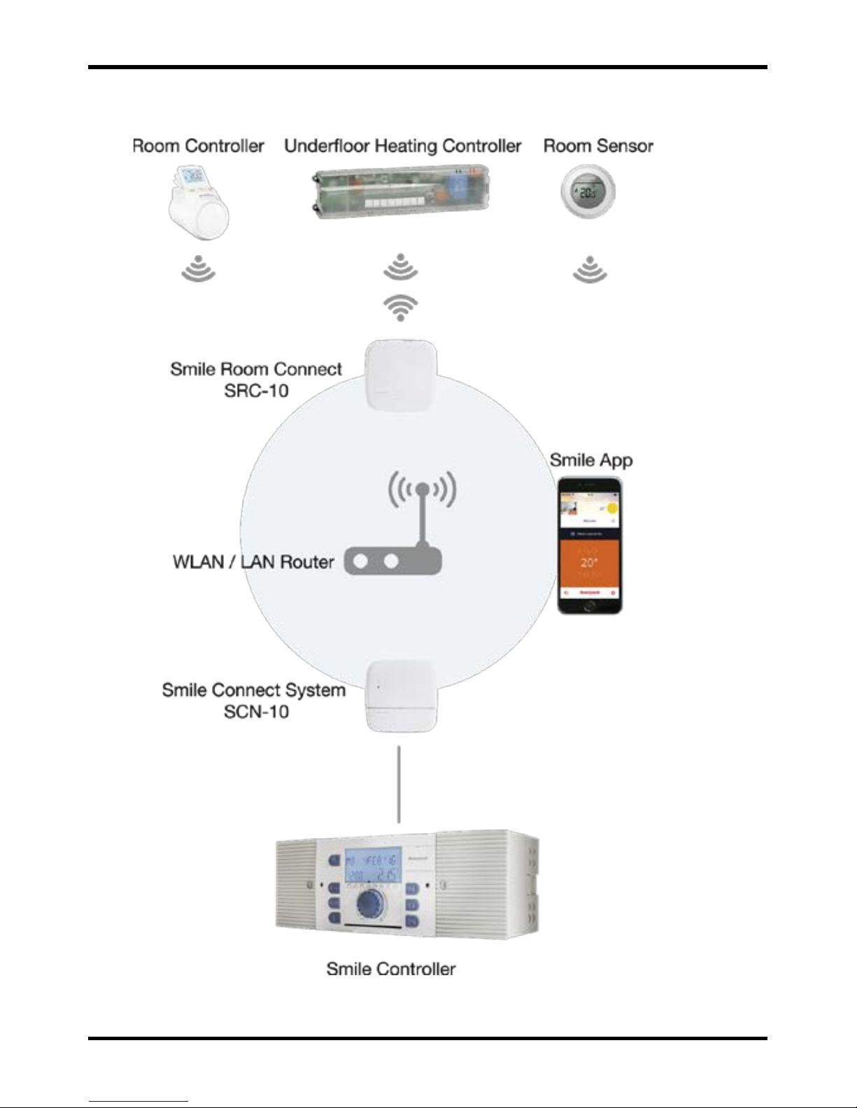
2 System Description
Fig. 1: SRC-10 system overview

MU1H-0635GE51 R1016 6
The SRC-10 is an upgradable module for the Smile Connect System.
Individual room control in accordance with EN 15232 is possible through a
boiler connection. To ensure individual room control, there are different
components that allow the temperature in each room to be selected.
Remote access via an app is also possible.
Smile Room Connect SRC-10 Installation Instructions
7 MU1H-0635GE51 R1016
The basic settings (min-max values, frost protecti on val ue, etc. ) for
individual rooms are given in the SCN-10, Pro menu under room
groups. From these settings, the system calculates a flow set point
which is transmitted to the controller. For more information on the
basic settings, see chapter 4.2 Rooms basic settings.
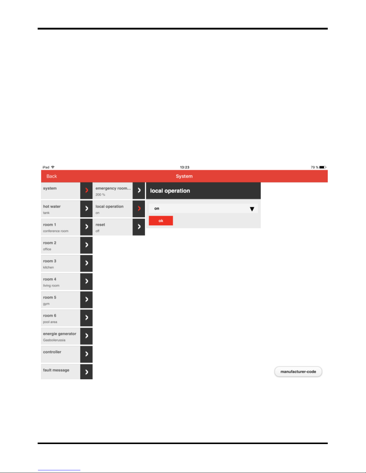
2.1 Local operation for HR92 and T87RFxx
You can turn off local operations for the radio components HR92 and
T87RFxx via the Pro menu. Local operation on the devices is ignored
with this setting.

MU1H-0635GE51 R1016 8
Smile Room Connect
The SRC-10 connects the Smile App wirelessly to the radiator
controllers and to the underfloor heating controllers in up to 16 rooms,
and connects individual room regulati on to the heat generat or.
T87RFxx
T87RFxx is a wireless digital temperature c ontrol with a room sensor
that can set individual temperatures.
HR92 and HCE80
HR92 and HCE80 are radio-controlled regulators for radi ators or for
underfloor heating. These communicat e with Smile Connect through
a radio protocol optimized for battery applicati ons.
HCF82
HCF82 is a wireless digital room temperature sensor that measures
room temperature.
Smile App
The Smile App is installed on mobile devices such as smart phones or
tablets (iOS or Android) and is used to operate the SRC-10. You can
download the app using the search term "Honeywell Smile" from the
App Store and from the Google Play Store free of charge.
WLAN/LAN Router (provided by the customer)
The customer's WLAN/LAN router allows the SDC regulator and Smile
Connect to operate and communicate via the Smile App.
2.2 Scope of supply
Check the content of the packaging. The following components are
included:
• Smile Room Connect (SRC-10) with integrated WiFi module (x 1),

Smile Room Connect SRC-10 Installation Instructions
9 MU1H-0635GE51 R1016
• Network cable (x 1),
• Wall power supply for Smile Room Connect (x 1),
• Operating instructions (x 1).
2.3 Accessories
The following component is available as an accessory and is essential
for start-up:
• SCI-10 installation kit, consisting of the USB-LAN adapter and
a network cable.

MU1H-0635GE51 R1016 10
3 Installation and electrical connection
Follow the specified sequence during instal l ation and start-up of
the SRC-10.
1. Install the SCN-10 completely.
2. Install the SRC-10.
3.1 Prerequisites and requirements
The SCN-10 requires an Ethernet network (LAN/WLAN)
including router.
In order to use the SRC-10, you will need a smart phone or tablet
(iOS versions which are under support of Apple, or Android 4.x or
higher from 8" with a 3G/4G mobile communications system (UMTS,
LTE)) as well as an on-site WLAN.
For start-up, you will need a standard laptop and the SCI-10 installation
kit, consisting of the USB-LAN adapter and a network cable.
Smile Room Connect SRC-10 Installation Instructions
11 MU1H-0635GE51 R1016
3.1.1 Installation
The SRC-10 is provided as a table-top device. Find a suitable
installation location that fulfills the following requirements:
• A 230-V earthed wall socket must be available.
• The installation locati on must be within the radio
coverage area.
• A LAN connection to the customer's network must be
available, or alternatively t he installat ion l ocat i on must
be within the customer's WLAN network coverage in
order to use the integrated WLAN module.
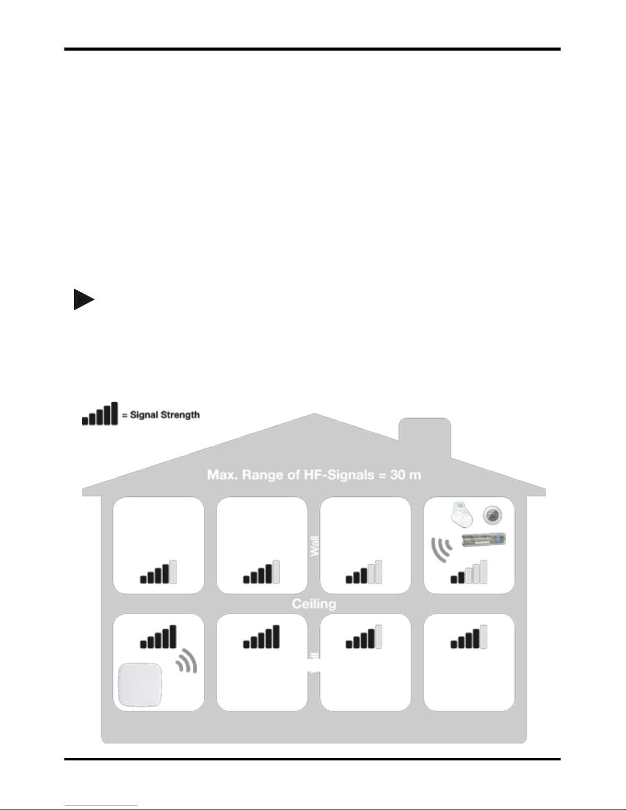
NOTE
The radio coverage is linked to the height of the installation location.
The SRC-10 should be placed at a height of 0.70-2 m (e.g., on top of
a cupboard). This height ensures the best possibl e radio coverage.
Position the SRC-10 at the selected installation location.

MU1H-0635GE51 R1016 12
Fig. 2: SRC-10 radio coverage
Smile Room Connect SRC-10 Installation Instructions
13 MU1H-0635GE51 R1016
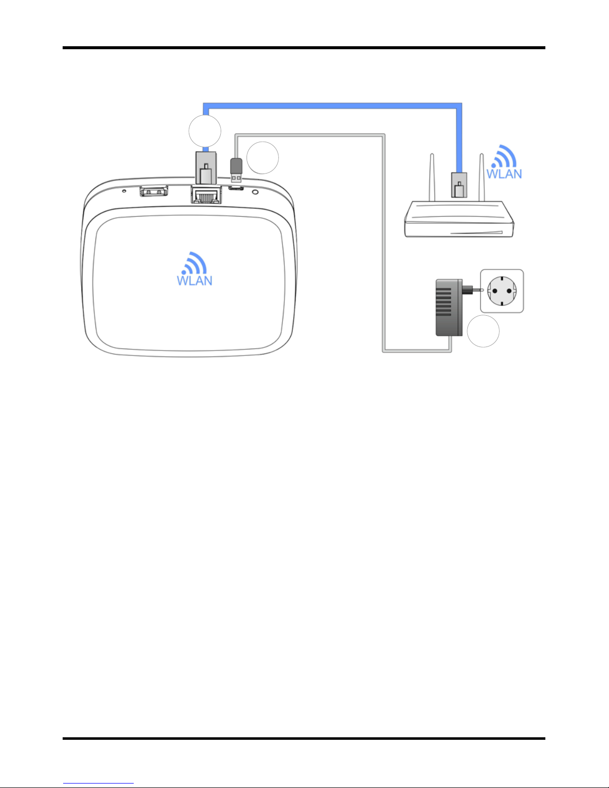
3.1.2 Electrical connection
Fig. 3: Smile Room Connect S RC-10
1. Connect the SRC-10 to the customer's LAN network:
- Via a network cable into an available Ethernet port on the
customer's internet rout er or switch. The length of the total
cable from the SRC-10 to the next switch or router must
not exceed 100 m.
- Alternatively, via a WLAN connection using the integrated
WLAN module in the SRC-10. Ask the customer for their
WLAN network access data—you will need this during the
start-up/initial setup, see chapter
4 Start-up/Initial setup.
2. Connect the AC adapter provided
.
3. Plug the AC adapter into an electrical outlet.
1
2
3

MU1H-0635GE51 R1016 14
4 Start-up/Initial setup
NOTE
Before you can configure the SRC-10, you must s et up the rooms that
are to be operated in advance in the SCN-10 and activate the
individual room regulator, see chapter 4.1, SCN-10 configuration.
Start-up includes configuring the SCN-10 via a browser (e.g., Internet
Explorer, Chrome, Firefox) on the connected PC/laptop.
Before start-up, please select the following LAN options in the
browser's local network setti ngs:
a. Activate DHCP (automatic address assignment).
b. Deactivate all proxy server options.
NOTE
Additional costs may be incurred owing to an update of the device
software being installed over the internet. This will depend on the
customer's internet tariff.

Smile Room Connect SRC-10 Installation Instructions
15 MU1H-0635GE51 R1016
4.1 SCN-10 configuration
The SCN-10 is configured on a PC/laptop using the setup wizard
(see detailed description in the Smile Connect System installation
instructions, MU1 H-0603GE51, chapter 4.1).
Plug the USB-LAN adapter into an available USB port on the upper
side of the Smile Connect.
Then connect the USB-LAN adapter via an Ethernet cable to the
network port of the PC/laptop.
Connect the USB-LAN adapter via an Ethernet cable to the network
port of the PC/laptop.
Switch on the PC/laptop and open the browser.
The setup wizard will start automatically in the browser shortly after.
If the setup wizard does not start automatically, then please enter the
address http://10.0.0.1
in the address bar of the browser.
The SCN-10 Main menu will appear.
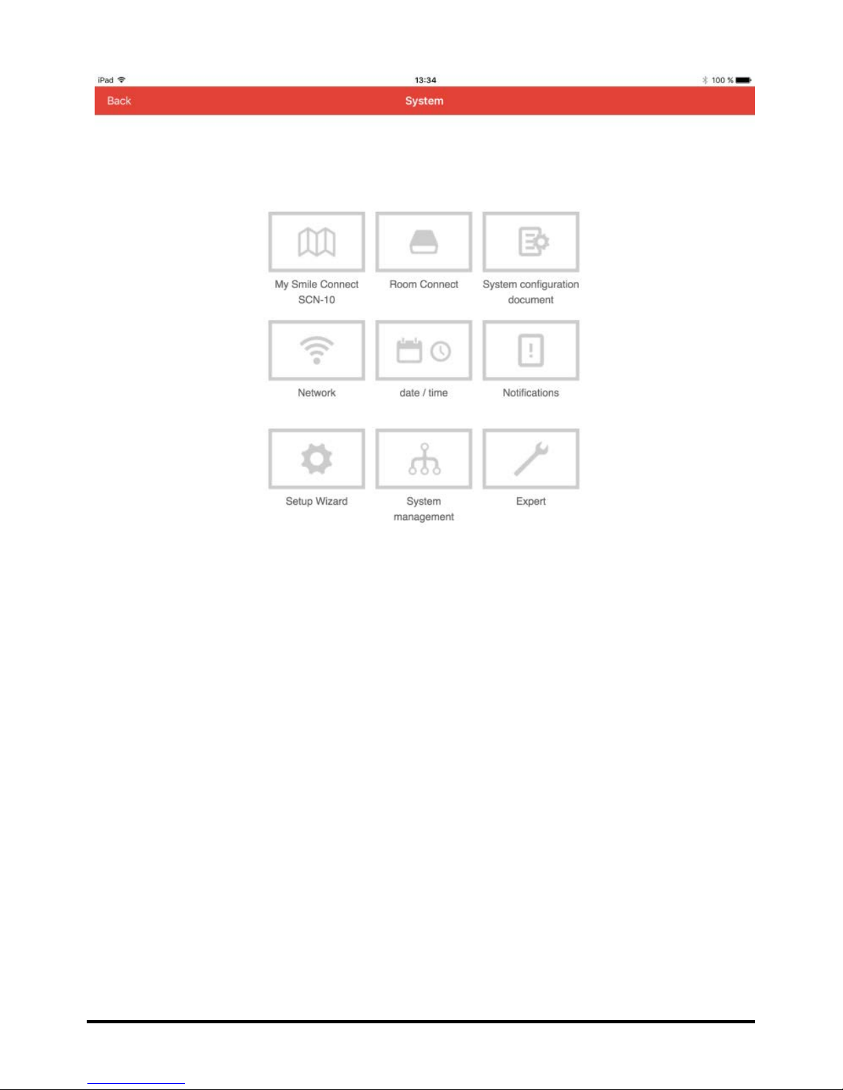
MU1H-0635GE51 R1016 16
1. Click on Setup Wizard.

Smile Room Connect SRC-10 Installation Instructions
17 MU1H-0635GE51 R1016
2. The Network menu will appear.
3. To access the next menu, press the button.
4. The Energ y Generator screen will appear.
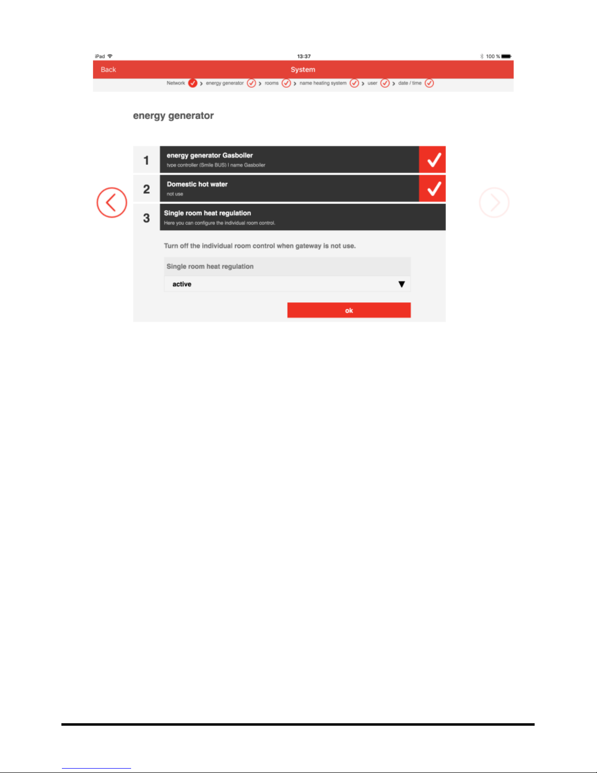
MU1H-0635GE51 R1016 18
5. Click on Single room heat regulation and select On in the
drop-down menu.
6. Activate individual room regul ation by pressing OK.
 Loading...