


SmartPAC 2 Press Automation Control
®
with Wintriss WPC Clutch/Brake Control
includes optional DiPro PAC and ProCam PAC
®
®®
1126800 Rev. 1 September 2003
Tech Support Hotline 800-586-8324 8-5 EST
Wintriss
Wintriss Controls Group
100 Discovery Way
Acton MA 01720-3648 USA
Phone (978) 264-9550 (800) 586-8324
Fax (978) 263-2491
3
PRINTED IN USA DA70194
www.wintriss.com

Requirements You Must Meet
When Installing and Using the Wintriss Clutch/Brake Control
The Wintriss Clutch/Brake Control (WPC) is designed solely for controlling operation of part-revolution metal
stamping presses. Before installing or using WPC, be sure you understand and follow these requirements:
!
DANGER
FULL REVOLUTION MECHANICAL POWER PRESSES AND OTHER MACHINES CANNOT BE STOPPED
IN MID-STROKE OR MID-CYCLE
• DO NOT use WPC clutch/brake control on full-revolution clutched machinery or other equipment that cannot be
stopped at any point in its stroke or cycle.
• Use WPC clutch/brake control only on part-revolution clutched mechanical power presses as defined in OSHA
1910.217 (b) (7). Refer also to ANSI B11.1-2001 6.12.
• Use WPC clutch/brake control only on rotating machinery that can be stopped at any point in its stroke or cycle.
Failure to comply with these instructions will result in death or serious injury.
!
DANGER
IMPROPER SAFEGUARDING
• Ensure that the press on which WPC clutch/brake control is used meets all of the OSHA and ANSI regulations for
safeguarding press systems in installation and use. WPC is not in itself a safeguarding device. Honeywell takes no
responsibility for injury if safeguarding devices are not installed or working properly.
• Install any two-hand control used as a safety device at least the safety distance away from the hazardous area; safety
distance is defined in the OSHA and ANSI regulations. Verify at each shift change that any moveable two-hand control
used as a safety device is located at least the safety distance away from the hazardous area.
• Install any light curtain or curtains at least the safety distance away from the hazardous area; safety distance is defined
in the OSHA and ANSI regulations.
• Install other safeguarding devices as needed to ensure operator safety. Follow the machine guarding requirements of
OSHA standard 1910.217 and any other regulations and standards that apply. Test safeguarding devices for correct
installation and operation after installation and after any modification or repair.
• Ensure that guarding is properly installed to prevent access to the machine over, under or around any guarding device.
Failure to comply with these instructions will result in death or serious injury.
!
DANGER
MORE OPERATORS THAN OPERATOR STATIONS
• Ensure that there are the same number of active operator stations as there are operators, if the press is not equipped
with properly installed and operating light curtains.
• During setup, lockout/tagout the press if there are more operators than operator stations.
• Verify at every shift change that there are the same number of active operator stations as there are operators, if the
press is not equipped with properly installed and operating light curtains.
Failure to comply with these instructions will result in death or serious injury.
!
DANGER
NON-SAFETY OUTPUTS USED FOR SAFETY FUNCTIONS
Use auxiliary outputs and cam channels for non-safety functions only. They cannot protect personnel from a moving
hazard.
Failure to comply with these instructions will result in death or serious injury.
Read additional
!
DANGER
and
!
WARNING
notices on following page.

!
DANGER
IMPROPER INSTALLATION, USE OR MAINTENANCE
• Ensure that the machinery complies with OSHA regulations 1910.217 and ANSI B11.1-2001.
• Follow all procedures in this manual. Perform only the tests and repairs listed in this manual. Use only factory-supplied
replacement parts. Ensure that all safety procedures are followed during installation and operation of WPC.
• Wire and install WPC and other equipment according to the requirements of OSHA 1910.147 Control of Hazardous
Energy (Lockout/ Tagout).
• Lockout/Tagout the press during all installation, modification, repair or maintenance procedures.
• Ensure that the dual safety valve used on the press complies with OSHA 1910.217 (b) (7) (xi). Contact manufacturer to
verify compliance of your model.
• Ensure that any foot control complies with OSHA 1910.217 (b) (7) (x).
• Ensure that WPC clutch/brake control is installed, tested and repaired by qualified personnel.
• Wire, install and maintain WPC clutch/brake control in accordance with the applicable safety standards. Carry out all
inspection procedures in OSHA 1910.217
• Install and maintain your machine guarding system according to OSHA standard 1910.217, ANSI B11.1, ANSI B11.19
and any other regulations and standards that apply. Ensure that guarding is properly installed to prevent access to the
machine over, under or around any guarding device.
• Perform all installation verification and checkout tests after installation and after any modification or repair of the WPC
clutch/brake control. Correct any problems before using the press.
• Maintain all presses as stated in the applicable regulations. Honeywell takes no responsibility in cases where stopping
mechanisms of machinery or other devices are not maintained or do not meet the applicable regulations or standards.
• Ensure that supervisors, die-setters, maintenance persons, machine operators, foremen, and any others responsible
for operation of the machinery have read and understood all instructions for use of the WPC clutch/brake control.
• DO NOT use touch buttons for any safeguarding use.
Failure to comply with these instructions will result in death or serious injury.
x
!
WARNING
MACHINERY NOT CONFIGURED OR WORKING PROPERLY
• Ensure that the press on which WPC clutch/brake control is used meets the machine guarding requirements of OSHA
standard 1910.217 and any other regulations and standards that apply.
• DO NOT operate a press equipped with WPC clutch/brake control if the machine or any of its stopping mechanisms is
not in proper working order.
Failure to comply with these instructions could result in death or serious injury.
!
WARNING
OTHER EQUIPMENT CONTINUING TO OPERATE
• Ensure that all operators and other affected personnel know which equipment may continue to operate and which will
not. Equipment that operates with the machinery connected to WPC clutch/brake control may continue to operate after
the press has received a stop signal.
Failure to comply with these instructions could result in death or serious injury.
!
WARNING
ELECTRIC SHOCK HAZARD
• Turn off and disconnect power from WPC clutch/brake control, the press and any other machinery it is
connected to before making any wiring connections. This includes power to the press’s motor.
Failure to comply with these instructions could result in death or serious injury.
The enforcement of the above requirements is beyond Honeywell’s ability to control. For proper WPC operation, it
is your responsibility to follow these requirements and any other requirements that may be specific to your
machinery.

Thank you for purchasing a Honeywell Wintriss Product. We appreciate your business and want to do
whatever we can to ensure your satisfaction. Wintriss products are built to stay on the job day after day,
and are backed by an ironclad guarantee, international standards approvals, and unbeatable support.
Whenever you need assistance or service, we back all our products with excellent spare parts inventories,
training programs, and prompt repair service. We would like to share with you a list of service options probably the largest number of service options offered in the industry.
•••• Technical Assistance
We offer a toll-free line for technical assistance. Call our Wintriss Tech Support Hotline at
1-800-586-TECH (8324) should you have any questions about your equipment. Our technical staff
is ready to assist you Monday through Friday, 8 a.m. to 5 p.m. EST. In many cases our experienced
technical staff can resolve your inquiry right over the phone.
•••• Return Authorization
Please call our “800” number for a return authorization (RA) number to return a product for repair.
Returned goods must arrive freight prepaid. In order to process your return quickly, we ask that you
provide us with the following pertinent information when you call: order number, order date,
shipping address, contact name and telephone number, and product type. The assigned RA number
should appear on all packages returning to Wintriss Controls Group to ensure prompt service. Please
be sure to carefully pack all returned items and ship to our Acton, MA location.
•••• Expedited Repair Program
Rush service providing 48 hour turn-around is available for most products upon request. A $50
Expedite Fee will be applied to our standard repair rate if the unit is not within its warranty period.
•••• Board Exchange Program
If your needs are urgent, you can take advantage of our Board Exchange (EX) program. The EX
program applies to SmartPAC, Wintriss Clutch/Brake Control (WPC), and all 1500 series products.
Call our “800” number between 8 a.m. to 5 p.m. EST and we will send a replacement to you
overnight. A fee does apply to this service. Contact Wintriss Tech Support at 800-586-8324 for
details.
•••• Service Center
Our major center for product service is located at our headquarters in Acton MA. If your equipment
requires repair, please contact us at 800-586-8324 to obtain a return authorization number.
Nationwide field service is also available. Contact the Wintriss Service Manager at
800-586-8324, ext. 1949 or Wintriss Tech Support group at 800-586- 8324.
•••• Product Training
We are also offer both product training and maintenance/troubleshooting courses at our Carol
Stream, IL and Acton, MA facilities. On-site training is available from the factory or through your
local Wintriss representative
•••• Restocking Charge
Returned goods are subject to a 20% restocking charge if returned for credit. The minimum charge
is $50, not to exceed $250 per item.
Whatever the product, we are committed to satisfying you with innovative engineering, quality
construction, reliable performance, and ongoing, helpful support. Call us whenever you need assistance.

Table of Contents
Chapter 1 – Introduction to SmartPAC 2 with WPC......................................... 1
SmartPAC 2................................................................................................................................................1
WPC and Control Reliability......................................................................................................................1
SmartPAC with WPC.................................................................................................................................2
How SmartPAC 2 with WPC Will Benefit Your Operation.......................................................................2
Standard features:...................................................................................................................................2
Optional Die Protection and Programmable Cam Switch Features: ......................................................3
SmartPAC 2 Front Panel ............................................................................................................................4
System Components ...................................................................................................................................5
WPC Options..............................................................................................................................................7
How SmartPAC 2 Works............................................................................................................................8
Settings You Can Make on SmartPAC 2....................................................................................................9
Sensors Available for Optional DiProPAC...............................................................................................11
Understanding Sensor Terminology.........................................................................................................12
Normally Open, Normally Closed .......................................................................................................12
Ready signal.........................................................................................................................................12
Impedance............................................................................................................................................13
Sensor Types........................................................................................................................................13
Considerations for Setting Sensor Stop Type...........................................................................................18
ProCamPAC Programmable Cams (Optional) .........................................................................................18
SmartPAC 2's Three Modes of Operation ................................................................................................19
Specifications: SmartPAC 2 with WPC...................................................................................................20
Chapter 2 – Installing WPC and SmartPAC 2 .................................................23
Part 1 – Installation Overview ..................................................................................................................26
Before You Start.......................................................................................................................................26
The first step – Checking the Press...........................................................................................................27
Installation Guidelines..............................................................................................................................27
Overview of the Installation .....................................................................................................................30
How to Connect Wires to Terminal Block Connectors ............................................................................30
How to Terminate Cable Shields..............................................................................................................31
Part 2 – Install and Wire WPC .................................................................................................................32
Mounting the WPC Control Enclosure.....................................................................................................33
Install WPC Without Enclosure................................................................................................................34
Wiring the WPC .......................................................................................................................................35
Slide Adjust Considerations.................................................................................................................35
Connecting AC Wiring to WPC ...............................................................................................................35
Installing and Wiring Dual Safety Valve and Sensors for Clutch and Counterbalance Air Pressure.......37
Dual Safety Valve ................................................................................................................................37
Air Pressure Sensors or Switches.........................................................................................................38
Install the Resolver ...................................................................................................................................41
Mounting and Wiring the Resolver......................................................................................................42
If You Replace Your Resolver.............................................................................................................43
Table of Contents page i
SmartPAC 2 with WPC Integration 1126700

1126800 SmartPAC 2 with WPC Integration
Chapter 2 – Installing WPC and SmartPAC 2, continued
Install the Overrun Limit Sensor Magnetic Switch...................................................................................44
Planning Your Overrun Sensor Installation .........................................................................................45
Mounting the Overrun Sensor Magnetic Switch..................................................................................45
Wiring the Overrun Sensor Magnetic Switch ......................................................................................46
Mounting and Wiring the Operator Station and Light Curtain(s).............................................................47
Using a Light Curtain on Your Press ...................................................................................................49
Mounting the Operator Station if You Do Not Use Light Curtains......................................................50
Using Two Light Curtains on Your Press ............................................................................................50
Connecting Other Wintriss Products to WPC...........................................................................................50
Wiring WPC User Inputs..........................................................................................................................52
Part 3 – Install and Wire WPC Options....................................................................................................55
Wiring Lockout Relay (Optional).............................................................................................................55
Wiring a Remote Reset Switch (Optional) ...............................................................................................56
Wiring Operator Mode Outputs (Optional) ..............................................................................................56
Wiring Foot Switch (Optional).................................................................................................................57
Installing One-hand Control (Optional)....................................................................................................58
Mounting One-hand Control Switch....................................................................................................58
“Light Curtain Break” Mode................................................................................................................60
Wiring One-hand Control to WPC.......................................................................................................61
Wiring Automatic Single Stroke/External Trip ........................................................................................62
Wiring Continuous on Demand ................................................................................................................62
Installing Multiple Operator Stations........................................................................................................63
Auxiliary Outputs (Optional)....................................................................................................................64
Wiring Auxiliary 1 Output (Optional)..................................................................................................64
Wiring Auxiliary 2 Output (Optional)..................................................................................................65
Wiring Auxiliary 3 Output (Optional)..................................................................................................66
Wire a Keylock Switch to Prevent Changes to WPC Settings in Program and Run (Optional)...............66
Installing Flywheel Speed Sensor (Optional Hardware Required)...........................................................67
Mounting and Wiring the Bar Control Enclosure (Optional) ...................................................................68
Part 4 – Install and Wire SmartPAC.........................................................................................................69
SmartPAC 2 the First Step—Checking the Press .....................................................................................69
Installing SmartPAC 2 Enclosure.............................................................................................................70
Installing SmartPAC 2 as a Panel Mount..................................................................................................72
Standard Enclosure Versus Optional Panel Mount ..............................................................................72
Preparation for Mounting SmartPAC 2 Using Your Enclosure ...........................................................72
Wiring between WPC and SmartPAC ......................................................................................................74
Connecting WPC’s Resolver to SmartPAC .........................................................................................74
Connecting Communications Between SmartPAC 2 and WPC...........................................................75
Connecting AC Wiring Between WPC and SmartPAC 2.........................................................................76
Connect Stop Circuits and Input Check Circuit to SmartPAC 2...............................................................77
Setting Input Check Voltage Switch ....................................................................................................77
Connecting SmartPAC 2 to a Network.....................................................................................................79
Part 5 – Install SmartPAC Options...........................................................................................................80
Adding or Upgrading ProCamPAC or DiProPAC....................................................................................80
page ii Table of Contents

SmartPAC 2 with WPC Integration 1126800
Chapter 2 – Installing WPC and SmartPAC 2, continued
Connecting Programmable Cam Channels...............................................................................................83
Making the Connections ......................................................................................................................83
Connecting DiPro Sensor Interface to SmartPAC 2.................................................................................90
Installing the DiPro Remote Connection Box ..........................................................................................92
Set Up High Speed Version of SmartPAC 2 with WPC (Optional) .........................................................94
Wiring Setup Mode Circuit ......................................................................................................................94
Wiring a Sensor-Disabled Output (Optional) ...........................................................................................94
Part 6 – Set Up SmartPAC 2 with WPC...................................................................................................95
Turn On Power to SmartPAC 2 and WPC................................................................................................96
Problems at Startup...................................................................................................................................98
Verify Proper Installation of ProCamPAC and/or DiProPAC Options ..................................................100
Initialize Press Parameters......................................................................................................................101
Create and Load a Test Tool Number.....................................................................................................103
Check and Set Direction of Resolver Rotation.......................................................................................104
Zero the Resolver....................................................................................................................................105
Set Top Stop Angle and Install Overrun Magnet....................................................................................107
Check Top Stop After You Change Top Stop Angle.........................................................................115
Prepare to Install Magnet for Overrun Limit Sensor..........................................................................116
Install Magnet for Overrun Sensor.....................................................................................................125
Check the ON and OFF Time of the Overrun Sensor.............................................................................126
Part 7 – Perform Checkout Tests ............................................................................................................127
WPC Power Supply Test ........................................................................................................................129
Check Safeguarding Devices..................................................................................................................130
Check Dual Safety Valve (DSV) Wiring................................................................................................132
Check the Emergency-Stop Circuit ........................................................................................................134
Check the Top Stop Circuit ....................................................................................................................135
System Static Test ..................................................................................................................................136
Anti-tiedown Test...................................................................................................................................138
Anti-repeat Test ......................................................................................................................................139
Shadow Light Curtain Test.....................................................................................................................140
Single Stroke Mode Test with Light Curtain..........................................................................................142
Single Stroke Mode Test Without Light Curtain(s)................................................................................145
Continuous Mode Test with Light Curtain.............................................................................................147
Continuous Mode Test Without Light Curtain(s)...................................................................................149
Foot Switch Test (with Optional Foot Switch).......................................................................................151
One-hand Control SwitchTests (with Optional One-hand Control) .......................................................153
Test for One-hand Control with “Light Curtain Break” Mode ..........................................................154
Test for One-hand Control Without “Light Curtain Break” Mode ....................................................155
Bar Mode Control Test – Optional.........................................................................................................156
User Inputs Test......................................................................................................................................157
Cam Channels Test (Optional – with ProCamPAC)...............................................................................157
Checkout Tests Complete.......................................................................................................................157
Part 8 – PC Board Illustrations and Wiring Tables.................................................................................158
Table of Contents page iii

1126800 SmartPAC 2 with WPC Integration
Chapter 3 – SmartPAC 2 Keyboard, Displays and Operating Modes .........171
Comparing SmartPAC 2 with Original SmartPAC.................................................................................173
SmartPAC 2 Keyboard ...........................................................................................................................174
Number Keys .....................................................................................................................................176
Clear Key ...........................................................................................................................................177
Help Key ............................................................................................................................................178
Cursor Keys........................................................................................................................................179
ENTER and RESET Keys..................................................................................................................181
Program/Run Key Switch...................................................................................................................183
Function Keys ....................................................................................................................................184
Hot Keys ............................................................................................................................................185
SmartPAC 2 Display...............................................................................................................................186
Selecting an Item on a Display...........................................................................................................187
The Three Operating Modes of SmartPAC 2..........................................................................................188
Initialization Mode..................................................................................................................................190
Program Mode ........................................................................................................................................192
Run Mode ...............................................................................................................................................194
Using Cursor Keys to Set Timing...........................................................................................................195
Screen Capture........................................................................................................................................199
Chapter 4 – SmartPAC 2 with WPC Initialization Mode................................201
SmartPAC 2 and Original SmartPAC.....................................................................................................202
How to Enter and Exit Initialization Mode.............................................................................................203
Initialize Press Parameters ......................................................................................................................204
RESOLVER ZERO ................................................................................................................................204
POSITION SENSOR..............................................................................................................................205
Position Sensor Mode ........................................................................................................................205
Resolver Motion Mode (Normal Motion – Link Motion)..................................................................206
Tool Number Mode............................................................................................................................206
Counter Setup Mode ..........................................................................................................................208
INSTALLED OPTIONS.........................................................................................................................209
PRESS NAME........................................................................................................................................210
SELECT CAM NAMES (Optional) .......................................................................................................211
AUTO ADVANCE and Slow RPM .......................................................................................................213
Setting Auto Advance Constant and Slow RPM................................................................................214
SET GLOBAL CAMS (Optional) ..........................................................................................................216
CUSTOM SENSOR NAMES (Optional)..............................................................................................218
SENSOR ENABLE MODE (Optional) ..................................................................................................219
Enabling Sensors................................................................................................................................219
Enabling or Disabling Setup Mode.........................................................................................................220
TOOL INFORMATION (Optional) .......................................................................................................221
PRESS CONTROL.................................................................................................................................225
User Interlocks ...................................................................................................................................225
Press Parameters.................................................................................................................................229
Stop Limit ..........................................................................................................................................230
Stopping Time and Stop Time Limit..................................................................................................230
Setting Stop Time Limit at Press Parameters.....................................................................................232
page iv Table of Contents

SmartPAC 2 with WPC Integration 1126800
Chapter 4 – SmartPAC 2 with WPC Initialization Mode, continued
PRESS CONTROL, continued
Setting the Start Time Limit at Press Parameters...............................................................................234
Using Auto Carry-up ..............................................................................................................................235
Setting Auto Carry-up Angle .............................................................................................................236
Setting Micro-Inch Time and Angle (Optional) .....................................................................................236
Setting Clutch and Counterbalance Air Pressure Limits ........................................................................238
Setting Shutdown and Flywheel Timer Limits (Optional).................................................................239
Setting the ACTS Angle (Optional)...................................................................................................240
Initialize Parameters...........................................................................................................................241
Press Options .....................................................................................................................................241
Setting Switches.................................................................................................................................242
Operator Mode Settings on Press Control Option Switch Screen......................................................249
Input Status ........................................................................................................................................250
SECURITY ACCESS.............................................................................................................................251
Selecting Security Access Options.....................................................................................................254
Reset Mode ........................................................................................................................................255
Changing Passwords ..........................................................................................................................255
Additional Security.................................................................................................................................257
PACNET.................................................................................................................................................258
SETUP NETWORK ...............................................................................................................................259
E-MAIL FUNCTION ........................................................................................................................259
SMARTVIEW FUNCTION ..............................................................................................................260
SETUP E-MAIL ................................................................................................................................260
CHANGE NETWORK SETTINGS ..................................................................................................262
PRESS TYPE.....................................................................................................................................263
DIAGNOSTICS......................................................................................................................................263
COMMUNICATIONS.......................................................................................................................264
SET CLOCK......................................................................................................................................266
UPDATE FIRMWARE .....................................................................................................................266
SAVE TO USB DISK........................................................................................................................267
Using SmartPAC 2 with a Link-motion Press........................................................................................268
Setting Link Motion...........................................................................................................................268
Using a Servofeed Interface with Link Motion..................................................................................269
Using a Computer Keyboard to Enter Names.........................................................................................270
Chapter 5 – SmartPAC 2 with WPC Program Mode ..................................... 273
SmartPAC 2 and Original SmartPAC.....................................................................................................274
Entering and Exiting Program Mode......................................................................................................275
TOOL MANAGER ................................................................................................................................276
Load an Existing Tool........................................................................................................................278
Delete a Tool......................................................................................................................................279
Tool Template....................................................................................................................................280
Create a New Tool .............................................................................................................................281
Copy an Existing Tool .......................................................................................................................282
Change Settings for an Existing Tool ................................................................................................282
Table of Contents page v

1126800 SmartPAC 2 with WPC Integration
Chapter 5 – SmartPAC 2 with WPC Program Mode, continued
Tool Program Menu................................................................................................................................285
TOOL NAME or TOOL ID ...............................................................................................................286
COUNTERS.......................................................................................................................................286
Setting or Clearing the Counter Presets..............................................................................................287
Setting or Clearing the Counter Values..............................................................................................288
Clearing the Total Hits Preset Message..............................................................................................288
Setting Counter Mode ........................................................................................................................288
Setting Parts/Stroke or Strokes/Part ...................................................................................................290
DIE PROTECTION................................................................................................................................292
Setting "Auto Enable by Tool" Counter Value ..................................................................................292
Naming the Sensor .............................................................................................................................294
Setting the "Auto Enable by Sensor and Tool" Counter Value..........................................................294
Setting Sensor Type ...........................................................................................................................295
Setting Stop Type...............................................................................................................................296
Setting the Ready Signal for a Green Sensor .....................................................................................297
Setting the Other Sensors for the Tool ...............................................................................................299
Going Back to the Main Programming Menu....................................................................................299
CAM SWITCH.......................................................................................................................................302
View Global Cams .............................................................................................................................304
View Cam Summary..........................................................................................................................305
Make an ON/OFF Setting for a Channel............................................................................................305
Multiple ON/OFFs for Cam Channels ...............................................................................................307
Selecting a Channel and Making a Timed Output Setting .................................................................309
Selecting a Channel and Making an Auto Advance Setting...............................................................311
Setting DSV ON Channel Timing......................................................................................................312
Set Other Channels for the Tool.........................................................................................................313
Delete Channel Settings .....................................................................................................................313
PRESS CONTROL.................................................................................................................................314
TOOL INFORMATION.........................................................................................................................315
SENSOR ENABLE/DISABLE & STATUS ..........................................................................................317
Controlling Which Sensors SmartPAC 2 Monitors............................................................................317
Enable or Disable All Sensors............................................................................................................318
Turn a Sensor OFF or ON..................................................................................................................318
RECALCULATE SETPOINTS (Optional)............................................................................................319
Chapter 6 – SmartPAC 2 with WPC Run Mode .............................................321
About Run Mode ....................................................................................................................................322
What you can and cannot do in Run mode.........................................................................................322
Why Some Tasks Are Duplicated in Each Mode...............................................................................322
Locking Run mode.............................................................................................................................322
Interrupted Stroke...............................................................................................................................322
Hot Keys ............................................................................................................................................323
SmartPAC 2 and Original SmartPAC.....................................................................................................324
Part 1 – Using SmartPAC 2 in Run Mode..............................................................................................325
How to Enter and Exit Run Mode...........................................................................................................325
Load A Tool Number Before Switching to Run Mode...........................................................................325
page vi Table of Contents

SmartPAC 2 with WPC Integration 1126800
Chapter 6 – SmartPAC 2 with WPC Run Mode, continued
Settings Locked in Run Mode, or Password Required ...........................................................................326
How to Use Hot Keys.............................................................................................................................327
Toggle Hot Keys ................................................................................................................................327
How to Program a Hot Key................................................................................................................328
How to Delete a Hot Key...................................................................................................................328
Main Run Menu......................................................................................................................................329
DISABLE (ENABLE) SENSORS (Optional)........................................................................................330
Setup Mode Message .........................................................................................................................331
COUNTERS ...........................................................................................................................................332
DIE PROTECTION (Optional) ..............................................................................................................333
Adjusting the Ready Signal for Green Sensors..................................................................................334
View Sensor Summary.......................................................................................................................337
Show Sensor Status............................................................................................................................338
CAM SWITCH (Optional) ....................................................................................................................340
View Cam Timing..............................................................................................................................341
View Global Cam Summary..............................................................................................................343
View Cam Summary..........................................................................................................................344
BRAKE MONITOR...............................................................................................................................345
Setting Stop Time, Stop Angle, and Start Time.................................................................................345
Start Time...........................................................................................................................................345
Stopping Angle ..................................................................................................................................346
Brake Warning...................................................................................................................................346
Performing the 90° Stop-Time Test...................................................................................................346
Calculating the Safety Distance .........................................................................................................348
PRESS CONTROL.................................................................................................................................353
Adjusting Top Stop Angle, Press Speed Limits, Counterbalance Setpoint, Main System Air Limit.353
Show Overrun Angles........................................................................................................................354
Viewing Actual Counterbalance and Main Air Pressure Limits (Optional).......................................354
TOOL INFORMATION (Optional) .......................................................................................................355
ERROR LOG..........................................................................................................................................356
LOAD NEW TOOL ...............................................................................................................................357
Load Next Tool Number (Available Only with PACNet Software) ..................................................357
Select a Tool to Load .........................................................................................................................359
MESSAGING.........................................................................................................................................361
Send E-mail to Wintriss Tech Support...............................................................................................362
TOGGLE HOT KEYS............................................................................................................................363
Part 2 – Operating the Press....................................................................................................................364
Interrupted Stroke...................................................................................................................................364
Mode Select Menu..................................................................................................................................365
Operating the Press in INCH mode ........................................................................................................366
Three Ways You Can Operate the Press in INCH Mode...................................................................366
Operating the Press in Single Stroke Mode............................................................................................368
One-hand Operation, Single Stroke Mode .........................................................................................369
Two-hand Operation, Single Stroke Mode ........................................................................................370
Foot Operation, Single Stroke Mode..................................................................................................372
Table of Contents page vii

1126800 SmartPAC 2 with WPC Integration
Chapter 6 – SmartPAC 2 with WPC Run Mode, continued
Operating the Press in Automatic Single Stroke Mode ..........................................................................373
Setting Prior Act Timing for Automatic Single Stroke ......................................................................374
Automatic Single Stroke Operating Instructions................................................................................374
Operating the Press in Continuous Mode ...............................................................................................375
Two-hand Operation, Continuous Mode............................................................................................375
Foot Operation, Continuous Mode.....................................................................................................376
Operating the Press in Continuous On Demand Mode...........................................................................377
Using One-hand Control.........................................................................................................................378
"Light Curtain Break" Mode..............................................................................................................378
Operating the Press Using One-hand Control ....................................................................................379
Operating the Press in BAR Mode..........................................................................................................380
Multiple Operator Stations......................................................................................................................380
Chapter 7 – SmartPAC 2 with WPC Fault Messages and Troubleshooting383
SmartPAC 2 and Original SmartPAC.....................................................................................................384
What Happens When You Get a Fault Message ................................................................................385
How to Clear the Fault Message from the Display ............................................................................385
Status Code #10 ......................................................................................................................................386
Interrupted Stroke ...................................................................................................................................386
Lockout...................................................................................................................................................387
Brake Monitor Brake Warning ...............................................................................................................388
Brake Monitor - Stop Time Exceeded* ..................................................................................................388
Customized Status Codes........................................................................................................................390
Description of Status Codes and How to Correct ...................................................................................390
Messages Displayed Due to Press Control Problems .............................................................................391
Resolver faults....................................................................................................................................392
Operational faults...............................................................................................................................393
Inter-processor failures.......................................................................................................................397
Input buffer test failures.....................................................................................................................397
Air pressure limits exceeded ..............................................................................................................398
Component failures ............................................................................................................................399
Customized Status Codes...................................................................................................................400
Light Curtain faults ............................................................................................................................402
Emergency stop circuit driver failure.................................................................................................404
Top stop circuit driver failure.............................................................................................................404
DSV Interface and Lockout relay failures..........................................................................................405
Loss of rotation ..................................................................................................................................406
Internal timing input failures..............................................................................................................406
Top Stop and Overrun Setting Faults.................................................................................................407
Overrun Limit Switch Fault ...............................................................................................................407
Overrun Limit Switch Test Angle Fault.............................................................................................408
Overrun Limit Switch Setting Fault ...................................................................................................408
Internal memory failures....................................................................................................................409
Messages Displayed for Equipment or Brake Monitor Problems ......................................................409
Messages displayed for programming problems................................................................................412
Messages Displayed When a Sensor Signals a Fault .........................................................................414
page viii Table of Contents

SmartPAC 2 with WPC Integration 1126800
Chapter 7 – SmartPAC 2 with WPC Fault Messages and Troubleshooting,
continued
Messages Displayed Due to Press Control Problems, continued
Miscellaneous Fault messages ...........................................................................................................416
Error Log ................................................................................................................................................418
E-mail Error Log and Other Information to Wintriss Tech Support..................................................419
Using the WPC Input Status Display......................................................................................................420
Install Revised Firmware into WPC.......................................................................................................423
Appendix A – OSHA Regulations and ANSI Standards...............................427
Section 1 OSHA Regulation 1910.217..................................................................................................427
Section 2 ANSI Standards for Presence-sensing Devices.....................................................................431
Appendix B – SmartPAC Preventive Maintenance (PM) Monitor (Optional)437
Comparison with Traditional Preventive Maintenance......................................................................437
How the PM Monitor Works..............................................................................................................438
Examples of How to Use the PM Monitor.........................................................................................438
SmartPAC 2 and Original SmartPAC.....................................................................................................440
Installing the PM Monitor ......................................................................................................................441
For New Systems from the Factory....................................................................................................441
For Existing Systems .........................................................................................................................441
Using the PM Monitor in Initialization Mode ........................................................................................441
How to Get into SmartPAC Initialization and PM Monitor...............................................................441
Initializing the PM Monitor ...............................................................................................................443
Assigning a New PM Password Number...........................................................................................445
Select PM Item Names.......................................................................................................................446
Using the PM Monitor in Run mode ......................................................................................................450
How to Get into SmartPAC Run mode ..............................................................................................450
A Tool Number Must Be Loaded Before Switching to Run Mode....................................................450
Viewing and modifying PM Alerts....................................................................................................451
Appendix C – Update SmartPAC 2 Firmware ...............................................453
Appendix D – SmartView Remote Viewing and E-mail Setup .....................455
Appendix E – Upgrade from Original SmartPAC to SmartPAC 2................ 457
Appendix F – Replacing SmartPAC 2 PC Board ..........................................459
Glossary of Terms ..........................................................................................461
Index ................................................................................................................471
Table of Contents page ix

1126800 SmartPAC 2 with WPC Integration
Wintriss User Manuals
SmartPAC2 with WPC Setup Sheet
ProCamPAC Cam Switch Setup Sheet Channels 1 - 8
ProCamPAC Cam Switch Setup Sheet Channels 9 – 16
DiProPAC Setup Sheet
Press Parameters Setup Sheet
Figures and Table at End of Manual
Figure A. SmartPAC 2 PC Board Illustration
Figure B. WPC LED Map
Table A. Wintriss Clutch/Brake Control (WPC) Connector Pinouts
Figure 1. Wintriss Clutch/Brake Control and SmartPAC 2 System Wiring
Figure 2. Wintriss Clutch/Brake Control Operator Station A Wiring
Figure 3. Wintriss Clutch/Brake Control External Wiring
Figure 4. Wintriss Clutch/Brake Control Shadow V & Herion XSV DSV Wiring
Figure 5. Wintriss Clutch/Brake Control Dual Operator Station Wiring
Figure 6. Wintriss Clutch/Brake Control, Shadow V & Ross EP DSV Wiring
Figure 7. Stop/Start Motor Control Station Wiring with Lockout
Figure 8. Wintriss Clutch/Brake Control OEM Operator Station with Separate One
Hand Control
Figure 9. WPC with Separate One-hand Control Wiring
Figure 10. DiProPAC with DSI 2 Wiring Diagram
Figure 11. DiProPAC with RCB Wiring Diagram
Figure 12. ProCamPAC 16 to Cam Output Wiring Diagram
Figure 13. SmartPAC 2 Loopback Wiring Connections
Figure 14. Cross-checked User Interlocks with Honeywell Interlocks
Figure 15. Wintriss Clutch/Brake Control Shadow VI and Herion XSZ DSV Wiring
Figure 16. Wintriss Clutch/Brake Control Integrated Shadow VI Wiring
page x Table of Contents

SmartPAC 2 with WPC Integration 1126800
List of Figures and Tables
Figure 1 - 1 SmartPAC 2 Front Panel...................................................................................................................4
Figure 1 - 2. Illustration of Operator Station .........................................................................................................6
Figure 1 - 3. How SmartPAC 2 Interprets Signals From a “Green” Sensor ....................................................... 14
Figure 1 - 4. How SmartPAC 2 Interprets Signals From a Sensor Set to "Green Quick Check" ........................15
Figure 1 - 5. How SmartPAC 2 Interprets Signals From a Sensor Set to "Green Constant" ............................... 16
Figure 2 - 1. Installation Overview......................................................................................................................29
Figure 2 - 2. Attaching Wires to Connector.........................................................................................................31
Figure 2 - 3. Connecting Shield Drain Wire to Ground Stud ..............................................................................31
Figure 2 - 4. WPC Mounting Dimensions...........................................................................................................33
Figure 2 - 5. Mounting dimensions for Non-enclosure WPC..............................................................................34
Figure 2 - 6. Setting Voltage Selector Switch .....................................................................................................36
Figure 2 - 7. Resolver ..........................................................................................................................................42
Figure 2 - 8. Overrun Sensor Magnetic Switch Installation Example ..................................................................44
Figure 2 - 9. Operator Station, Side Buttons........................................................................................................48
Figure 2 - 10. Operator Station, Top Buttons......................................................................................................49
Table 2 - 1. User Inputs (Interlocks), SmartPAC with WPC............................................................................... 54
Figure 2 - 11. One Way to Wire WPC Operator Mode Outputs..........................................................................56
Figure 2 - 12. One-hand Control Switch Dimensions..........................................................................................59
Figure 2 - 13. One-hand Control Switch Base, Showing Mounting Holes.......................................................... 60
Figure 2 - 14. Wiring Connections in One-hand Control Switch ........................................................................60
Figure 2 - 15. Multiple Operator Station Configurations ....................................................................................63
Figure 2 - 16. Installing the LMCS and Magnets ................................................................................................67
Figure 2 - 17. Bar Control Enclosure Mounting Dimensions..............................................................................68
Figure 2 - 18. SmartPAC 2 Mounting Dimensions, Enclosure............................................................................71
Figure 2 - 19. SmartPAC 2 Mounting and Cutout Dimensions, Panel Mount.....................................................73
Table 2 - 2. Resolver Wiring on SmartPAC 2 .....................................................................................................75
Figure 2 - 20. Wiring AC to SmartPAC 2, Top Right Inside Enclosure..............................................................76
Figure 2 - 22. Input check switch (S101) ............................................................................................................78
Table 2 - 3. Wiring to Input Check and Stop Circuits .........................................................................................78
Figure 2 - 23. ProCamPAC Output Assembly.....................................................................................................85
Figure 2 - 24. Cam Outputs Board ......................................................................................................................86
Table 2 - 4. ProCamPAC to Cam Output Assembly TB301, Cams 1-8..............................................................87
Table 2 - 5. ProCamPAC to Cam Output Assembly TB301, Cams 9-16............................................................87
Table 2 - 6. Making Connections to Relays.........................................................................................................88
Figure 2 - 25. Connector TB302 and TB303 for Wiring Relays to Equipment...................................................88
Figure 2 - 26. How to Connect Suppressors Across the Load .............................................................................89
Table 2 - 7. SmartPAC 2 to DSI 2 DiPro Sensor Interface, Sensors 1-8.............................................................91
Table 2 - 8. SmartPAC 2 to DSI 2 DiPro Sensor Interface, Sensors 9-16...........................................................91
Figure 2 - 27. DiPro Remote Connection Box for Sensors..................................................................................92
Table 2 - 9. DiPro RCB to SmartPAC 2.............................................................................................................. 93
Table 2 - 10. DiPro RCB to SmartPAC 2 (continued).........................................................................................93
Figure 2 - 28. SmartPAC 2 Startup Screen..........................................................................................................96
Figure 2 - 29. Main Program Menu..................................................................................................................... 97
Figure 2 - 30. SmartPAC 2 Main Initialization Menu .........................................................................................97
Figure 2 - 31. List of Installed Options..............................................................................................................100
Figure 2 - 32. WPC Initialization Menu ............................................................................................................102
Figure 2 - 33. "Press Parameters" Display in SmartPAC's Initialization Mode.................................................102
Figure 2 - 34. Initialize Parameters Warning Message......................................................................................102
Figure 2 - 35. “Resolver Zero” Screen ..............................................................................................................106
Table 2 - 11. Top Stop Angle 240
Table 2 - 12. Top Stop Angle bet. 241
Table 2 - 13. Top Stop Angle bet. 271
Table 2 - 14. Top Stop Angle 301
Figure 2 - 36. Installing Magnet for Overrun Sensor.........................................................................................125
° or less: Mounting Overrun Magnet ..........................................................117
° and 270° : Mounting Overrun Magnet................................................119
° and 300° : Mounting Overrun Magnet.................................................121
° or Greater: Mounting Overrun Magnet ....................................................123
Table of Contents page xi

1126800 SmartPAC 2 with WPC Integration
List of Figures and Tables
Figure 2 - 37. WPC Processor Board Layout ....................................................................................................159
Figure 2 - 38. WPC Power Supply Board Layout..............................................................................................160
Figure 2 - 39. WPC Serial Interface Board Layout............................................................................................161
Figure 2 - 40. SmartPAC 2 Board, Location of Components ............................................................................162
Figure 2 - 41. DiProPAC Boards, Location of Components..............................................................................163
Figure 2 - 42. ProCamPAC Boards, Location of Important Components .........................................................164
Figure 2 - 43. ProCamPAC and DiProPAC Boards Installed on SmartPAC 2 Board.......................................165
Table 2 - 15. WPC Wiring: Resolver................................................................................................................166
Table 2 - 16. WPC Wiring: Power Supply Connectors ...................................................................................166
Table 2 - 17. SmartPAC 2 Wiring: Resolver (TB101) ....................................................................................166
Table 2 - 18. SmartPAC 2 Wiring: Input Check and Stop Circuits (TB102) ..................................................167
Table 2 - 19. SmartPAC 2 Wiring: SFI Port (1) and Module Port (2) (TB103) ...............................................167
Table 2 - 20. SmartPAC 2 Wiring: Special Port (3) and PACNet Port (4) (TB104) ........................................168
Table 2 - 21. SmartPAC 2 Wiring: Spare 1 Port (5) and WPC Port (6) (TB105)............................................168
Table 2 - 22. SmartPAC 2 Wiring: Spare 3 Port (7) and Spare 4 Port (8) (TB106) ........................................169
Table 2 - 23. SmartPAC 2 Wiring: Aux I/O (TB107) ......................................................................................169
Figure 3 - 1. Front Panel, SmartPAC 2 with WPC Integration..........................................................................171
Figure 3 - 2. Differences Between SmartPAC 2 and Original SmartPAC.........................................................173
Figure 3 - 3. SmartPAC 2 Keyboard..................................................................................................................174
Figure 3 - 4. Stroke Select Key Switch...............................................................................................................175
Figure 3 - 5. Number Keys ................................................................................................................................176
Figure 3 - 6. Numeric Entry Box (left); Alphabetic Entry Box (right) ..............................................................176
Figure 3 - 7. Alphanumeric Mode Entry Box....................................................................................................176
Figure 3 - 8. HELP Key.....................................................................................................................................178
Figure 3 - 9. Cursor Keys and Help Key ...........................................................................................................179
Figure 3 - 10. Highlighted Item on Run Menu ..................................................................................................179
Figure 3 - 11. ENTER Key................................................................................................................................181
Figure 3 - 12. RESET Key.................................................................................................................................182
Figure 3 - 13. Function Keys .............................................................................................................................184
Figure 3 - 14. Run Main Menu, Showing Hot Keys Programmed ....................................................................185
Figure 3 - 15. SmartPAC 2 Display, Run Mode................................................................................................186
Figure 3 - 16. “ENABLE SENSORS” Is Highlighted in Main Run Menu........................................................187
Figure 3 - 17. The Three Operating Modes, Showing Main Menus ..................................................................188
Table 3 - 1. Initialization, Program and Run Modes..........................................................................................189
Figure 3 - 18. Initialization Mode Main Menu ..................................................................................................190
Figure 3 - 19. Navigation Example: Initialization Mode..................................................................................191
Figure 3 - 20. Program Mode Main (Top) Menu...............................................................................................192
Figure 3 - 21. Navigation Example: Program Mode.........................................................................................193
Figure 3 - 22. Run Mode Main (Top) Menu......................................................................................................194
Figure 3 - 23. Navigation Example: Run Mode................................................................................................195
Figure 3 - 24. Setting Cam Timing....................................................................................................................196
Figure 3 - 25. ON at 1
Figure 3 - 26. Setting ON Angle........................................................................................................................197
Figure 3 - 27. Setting OFF Angle ......................................................................................................................198
Figure 4 - 1. Main Initialization Menu ..............................................................................................................201
Figure 4 - 2. SmartPAC 2 and Original SmartPAC...........................................................................................202
Figure 4 - 3. SmartPAC 2 Initialization Main Menu .........................................................................................203
Figure 4 - 4. Position Sensor Display ................................................................................................................205
Table 4 - 1. Numeric and Alpha-numeric Tool Number Modes........................................................................207
Figure 4 - 5. List of Installed Options................................................................................................................209
Figure 4 - 6. “Select Cam Names” display ........................................................................................................211
Figure 4 - 7. Selecting Cam Name for “Channel 1” ..........................................................................................212
Figure 4 - 8. Custom Name Entry Box..............................................................................................................212
Figure 4 - 9. Illustrating “Auto Advance and Slow RPM”................................................................................214
° , OFF at 0° ....................................................................................................................197
page xii Table of Contents

SmartPAC 2 with WPC Integration 1126800
List of Figures and Tables
Figure 4 - 10. Number Entry Box......................................................................................................................215
Figure 4 - 11. Global Cams, Select Cam Channel.............................................................................................217
Figure 4 - 12. Global Cam Timing Type...........................................................................................................217
Figure 4 - 13. Custom Naming Sensors.............................................................................................................218
Figure 4 - 14. Sensor Enable mode (used with DiProPAC only) ......................................................................219
Figure 4 - 15. Main Initialization Menu ............................................................................................................220
Figure 4 - 16. Setup Mode Status ......................................................................................................................220
Figure 4 - 17. Tool Information Setup...............................................................................................................221
Figure 4 - 18. Tool Information Names.............................................................................................................222
Figure 4 - 19. Text Entry Box............................................................................................................................222
Figure 4 - 20. Units Selection Menu..................................................................................................................223
Table 4 - 2. Units for Tool Information setup....................................................................................................223
Figure 4 - 21. Completed Tool Number Information screen .............................................................................224
Table 4 - 3. Decimal places and formats ...........................................................................................................224
Figure 4 - 22. Press Control Initialization Mode ...............................................................................................225
Figure 4 - 23. "User Interlock" Display.............................................................................................................227
Figure 4 - 24. "Select Name" Display................................................................................................................228
Table 4 - 4. User Input (Interlock) Names.........................................................................................................228
Figure 4 - 25. Press Control Parameter Menu ...................................................................................................229
Figure 4 - 26. Selecting "Brake Monitor" from SmartPAC's Run Menu........................................................... 231
Figure 4 - 27. Viewing "Stop Time" in Run Mode............................................................................................ 231
Figure 4 - 28. WPC Initialization Menu ............................................................................................................233
Figure 4 - 29. "Press Parameters" Display in SmartPAC's Initialization Mode.................................................233
Figure 4 - 30. Selecting "Auto Carry-up Angle" ...............................................................................................236
Figure 4 - 31. "Micro-Inch" Display..................................................................................................................237
Figure 4 - 32. "Press Parameters" screen...........................................................................................................240
Figure 4 - 33. Press Control Option Switches ...................................................................................................241
Table 4 - 5. Switch 1 and Switch 2 Settings for Different Top Stop Angles.....................................................242
Table 4 - 6. Switch 3 Settings for One-hand Control or Foot Switch Mode......................................................243
Table 4 - 7. Switch 4 Settings for Auto Compensated Top Stop.......................................................................244
Table 4 - 8. Switch 5 Setting for Prior Act Timing ...........................................................................................245
Table 4 - 9. Switch 6 Setting for Single or Dual Light Curtains........................................................................246
Table 4 - 10. Switch 7 Setting to Enable/Disable Changes to Stop Time Limit and Auto Carry-up Angle ......247
Table 4 - 11. Switch 8 Settings for Top Stop with F and H Errors....................................................................248
Table 4 - 12. Switch 8 Setting for Auxiliary 1 Response to Interrupted Stroke ................................................249
Figure 4 - 34. “Enter Your Password” Screen................................................................................................... 252
Table 4 - 13. Security Access Settings ..............................................................................................................253
Figure 4 - 35. Security Access Menu.................................................................................................................254
Figure 4 - 36. Set Passwords Menu...................................................................................................................256
Figure 4 - 37. “Enter a New Password” Screen.................................................................................................256
Figure 4 - 38. Press Control Adjustments Locked.............................................................................................257
Figure 4 - 39. PACNet Set Communications Menu ..........................................................................................258
Figure 4 - 40. Network Setup Menu..................................................................................................................259
Figure 4 - 41. Setup Email Screen.....................................................................................................................260
Table 4 - 14. Setup E-mail Items....................................................................................................................... 262
Figure 4 - 42. Diagnostics Menu .......................................................................................................................263
Figure 4 - 43. Communications.........................................................................................................................264
Figure 4 - 44. Communications Data Combined (Left), Split (Right)...............................................................265
Figure 4 - 45. Clock Setting Screen...................................................................................................................266
Figure 4 - 46. Alphabetic Entry Window ..........................................................................................................271
Figure 5 - 1. Program Mode Main Menu...........................................................................................................273
Figure 5 - 2. SmartPAC 2 and Original SmartPAC........................................................................................... 274
Figure 5 - 3. Program Mode Main Menu...........................................................................................................276
Figure 5 - 4. Tool Manager................................................................................................................................277
Table of Contents page xiii

1126800 SmartPAC 2 with WPC Integration
List of Figures and Tables
Figure 5 - 5. Load Tool Information Box ..........................................................................................................278
Figure 5 - 6. Load Tool Warning Box...............................................................................................................279
Figure 5 - 7. Confirmation Message to Delete Tool ..........................................................................................279
Figure 5 - 8. Numeric Entry Box (left); Alpha-numeric Entry Box (right) .......................................................281
Figure 5 - 9. Tool Manager................................................................................................................................282
Figure 5 - 10. Load Tool Warning Box .............................................................................................................284
Figure 5 - 11. Tool Programming Menu............................................................................................................285
Figure 5 - 12. Tool Name Entry Box (left); Tool Number Entry Box (right)....................................................286
Figure 5 - 13. Counter display...........................................................................................................................287
Figure 5 - 14. Counter Setup Mode Menu.........................................................................................................289
Figure 5 - 15. Advanced counter mode..............................................................................................................291
Figure 5 - 16. Setting Parts/Stroke or Strokes/Part............................................................................................291
Figure 5 - 17. Setting "Auto Enable by Tool" Counter......................................................................................293
Figure 5 - 18. List of sensors to program...........................................................................................................293
Figure 5 - 19. Naming the Sensor......................................................................................................................294
Figure 5 - 20. Setting "Auto enable by sensor" counter.....................................................................................295
Figure 5 - 21. Setting sensor type ......................................................................................................................295
Figure 5 - 22. "Setting stop type" display..........................................................................................................296
Figure 5 - 23. Setting critical angle for variable-stop sensors............................................................................297
Figure 5 - 24. Example of a Programmed Ready Signal for Part Ejection ........................................................298
Figure 5 - 25. Setting "green special" sensor.....................................................................................................299
Figure 5 - 26. Load Tool Warning Box .............................................................................................................300
Figure 5 - 27. Cam Program Menu....................................................................................................................303
Figure 5 - 28. Global Cam Summery.................................................................................................................304
Figure 5 - 29. Cam Summary.............................................................................................................................305
Table 5 - 1. Examples of Using Extra ON/OFFs, 8-channel Unit .....................................................................307
Table 5 - 2. Examples of Using Extra ON/OFFs, 16-channel Unit ...................................................................307
Figure 5 - 30. Select Type of Cam Timing........................................................................................................306
Figure 5 - 31. Programming Channel 1, “Part blow-off”...................................................................................306
Figure 5 - 32. One ON/OFF Arc........................................................................................................................308
Figure 5 - 33. Add a New Arc ...........................................................................................................................308
Figure 5 - 34. Selected and Inactive Arcs..........................................................................................................309
Figure 5 - 35. A Timed Output Channel............................................................................................................310
Figure 5 - 36. An Auto Advance Channel .........................................................................................................312
Figure 5 - 37. Set DSV ON Delay Time............................................................................................................313
Figure 5 - 38. Press Control Parameters ............................................................................................................314
Figure 5 - 39. Tool Number Information Screen...............................................................................................315
Figure 5 - 40. Text Entry Box............................................................................................................................316
Figure 5 - 41. Sensor ON/OFF Status................................................................................................................317
Figure 5 - 42. Recalculate Setpoints Warning Box............................................................................................319
Figure 6 - 1. Run Menu......................................................................................................................................321
Figure 6 - 2. SmartPAC 2 and Original SmartPAC...........................................................................................324
Figure 6 - 3. No Tool Loaded Warning .............................................................................................................325
Figure 6 - 4. “Enter Your Password” Display....................................................................................................326
Figure 6 - 5. Run Main Menu, Showing Hot Keys Programmed ......................................................................327
Figure 6 - 6. Hot Keys Instruction Box .............................................................................................................328
Figure 6 - 7. Main Run Menu............................................................................................................................329
Figure 6 - 8. Display Showing "Sensors Enabled" or "Sensors Disabled" ........................................................331
Figure 6 - 9. Modifying counters screen............................................................................................................332
Figure 6 - 10. Die Protection Menu...................................................................................................................333
Figure 6 - 11. Adjust Ready Signal....................................................................................................................335
Figure 6 - 12. Sensor Summary Screen .............................................................................................................337
Figure 6 - 13. Show Sensor Status.....................................................................................................................338
Figure 6 - 14. Cam Switch Menu.......................................................................................................................340
page xiv Table of Contents

SmartPAC 2 with WPC Integration 1126800
List of Figures and Tables
Figure 6 - 15. Viewing Cam Timing .................................................................................................................342
Figure 6 - 16. Viewing Global Cams.................................................................................................................343
Figure 6 - 17. Cam Summary ............................................................................................................................344
Figure 6 - 18. Using "Brake Monitor" Display for 90° Test..............................................................................347
Figure 6 - 19. Distance Between Pinch Point and Light Curtain on a Press......................................................348
Figure 6 - 20. "Press Control" Display in Run Mode .........................................................................................353
Figure 6 - 21. Show Overrun Angles.................................................................................................................354
Figure 6 - 22. Tool Information Screen.............................................................................................................355
Figure 6 - 23. Error Log Display.......................................................................................................................356
Figure 6 - 24. Next Tool Number Display.........................................................................................................358
Figure 6 - 25. Load Tool Warning Box .............................................................................................................358
Figure 6 - 26. Tool Manager Screen..................................................................................................................359
Figure 6 - 27. Tool to Be Loaded ......................................................................................................................359
Figure 6 - 28. Load Tool Warning Box .............................................................................................................360
Figure 6 - 29. E-mail, Select Recipient..............................................................................................................361
Figure 6 - 30. Messaging, Select Message.........................................................................................................362
Figure 6 - 31. Sample E-mail to Wintriss Tech Support....................................................................................363
Figure 6 - 32. Toggle Hot Keys 1 and 2 ............................................................................................................363
Figure 6 - 33. Mode Select Menu......................................................................................................................365
Figure 7 - 1. SmartPAC 2 and Original SmartPAC........................................................................................... 384
Figure 7 - 2. Error Code Box.............................................................................................................................385
Figure 7 - 3. Counter Preset Message Box ........................................................................................................385
Figure 7 - 4. Status code #10.............................................................................................................................386
Figure 7 - 5. Lockout Message..........................................................................................................................387
Figure 7 - 6. Stop Time Exceeded Message ...................................................................................................... 388
Figure 7 - 7. User Input Status Code Message ..................................................................................................390
Table 7 - 1. User Inputs (Interlocks), SmartPAC with WPC.............................................................................. 401
Figure 7 - 8. Error Log, Accessed from Run Mode...........................................................................................418
Figure 7 - 9. E-mailing Error Log to Wintriss Tech Support.............................................................................419
Figure 7 - 10. WPC Initialization menu.............................................................................................................420
Figure 7 - 11. Display WPC Input Status Menu................................................................................................ 421
Figure 7 - 12. Display of Buttons/Switches Input Status....................................................................................421
Figure 7 - 13. Display of Estops/Top Stops Input Status...................................................................................422
Figure 7 - 14. Display of Interlock Input Status ................................................................................................422
Table B - 1. Preventive Maintenance Items.......................................................................................................439
Table B - 2. PM Tracking Units ........................................................................................................................439
Figure B - 1. SmartPAC 2 and Original SmartPAC .......................................................................................... 440
Figure B - 2. "PM Monitor" Highlighted at SmartPAC Initialization Menu.....................................................442
Figure B - 3. PM Password Screen....................................................................................................................442
Figure B - 4. PM Password Screen....................................................................................................................444
Figure B - 5. PM Entry Screen .......................................................................................................................... 444
Figure B - 6. Initialize PM Screen.....................................................................................................................445
Figure B - 7. Initialize Warning Screen.............................................................................................................445
Figure B - 8. PM Monitor Screen......................................................................................................................446
Figure B - 9. Displaying Available List of PM Names......................................................................................447
Figure B - 10. Alpha-numeric Display Superimposed over PM Names Screen ................................................447
Figure B - 11. Selecting Tracking Unit of Measure...........................................................................................448
Figure B - 12. Superimposed Number Display..................................................................................................448
Figure B - 13. Example .....................................................................................................................................449
Figure B - 14. "PM Monitor" Highlighted at SmartPAC Run Menu.................................................................450
Figure B - 15. Display Showing PM Monitor in "Normal" Status Mode ..........................................................451
Figure B - 16. Shows "Slide Adjust Motor" in "Alert" Mode ...........................................................................452
Table of Contents page xv

1126800 SmartPAC 2 with WPC Integration
How to use the manual
This is the installation and reference manual for SmartPAC. It has information about how to
install SmartPAC and use all the displays to make die protection sensor settings and
programmable cam settings.
Chapter 1 introduces you to SmartPAC, tells how it works — specifically about the optional
die protection (DiProPAC) and programmable cam (ProCamPAC) features, and explains
how to use this product.
Chapter 2 is the installation chapter. Use it to install SmartPAC if you are installing it
yourself. This chapter includes installation of the DiProPAC and ProCamPAC options.
Chapter 3 is an introduction to the SmartPAC displays and keyboard. Read this chapter to get
started using SmartPAC. It shows you how to select items on the SmartPAC displays and
how to perform key tasks. It also explains the various keys available. This chapter is the
place to start for learning how to use the SmartPAC displays and keyboard.
Chapter 4 explains how to use SmartPAC in Initialization mode. Use it to look up things you
need to know about using SmartPAC in Initialization mode.
Chapter 5 explains how to use SmartPAC in Program mode. Use it to look up things you
need to know about Program mode.
Chapters 6 explains how to use SmartPAC in Run mode. You can look up things you need to
know about Run mode.
Chapter 7 shows you fault messages or other types of messages you will see on your display
when SmartPAC sends a stop command to the press or when there is an equipment or
software problem. What the message means and how to correct the problem is explained. Use
this chapter to learn about all the SmartPAC diagnostic messages.
Appendix A gives excerpts from OSHA and ANSI standards.
Appendix B is about the optional PM (Preventative Maintenance) Monitor available with
SmartPAC. It explains what it is, how it works, and application examples. It also provides
instructions on using it in Initialization and Run modes (not used in Program mode).
Appendix C gives instructions for updating SmartPAC 2 program.
Appendix D gives instructions for using SmartView remote viewing utility.
Appendix E gives instructions for upgrading from an original SmartPAC to a SmartPAC 2.
Appendix F gives instructions for replacing the SmartPAC 2 PC board.
A Glossary of Terms gives definitions of key terms related to SmartPAC.
page xvi Table of Contents

SmartPAC 2 with WPC Integration 1126800
Important Highlighted Information
Important danger, warning, caution and notice information is highlighted throughout the
manual as follows:
!
DANGER
A DANGER symbol indicates an imminently hazardous situation, which, if not avoided, will
result in death or serious injury.
!
WARNING
A WARNING symbol indicates a potentially hazardous situation, which, if not avoided, could
result in death or serious injury.
CAUTION
A CAUTION symbol indicates a potentially hazardous situation, which, if not avoided, may
result in property damage.
NOTICE
A NOTICE symbol indicates important information that must be remembered and aids in job
performance.
Table of Contents page xvii

1126800 SmartPAC 2 with WPC Integration
Warranty
Honeywell International warrants that Honeywell / Wintriss electronic controls are free
from defects in material and workmanship under normal use and service for a period of
one year (two years for Shadow light curtains) from date of shipment. All software
products (PACNet and RSR), electro-mechanical assemblies, and sensors are warranted
to be free from defects in material and workmanship under normal use and service for a
period of 90 days from date of shipment. Honeywell's obligations under this warranty are
limited to repairing or replacing, at its discretion and at its factory or facility. Any
products which shall, within the applicable period after shipment, be returned to
Honeywell’s Wintriss Controls Group freight prepaid, and which are, after examination,
disclosed to the satisfaction of Honeywell, to be defective. This warranty shall not apply
to any equipment which has been subjected to improper installation, misuse,
misapplication, negligence, accident, or unauthorized modification. The provisions of
this warranty do not extend the original warranty of any product which has either been
repaired or replaced by Honeywell. No other warranty is expressed or implied.
Honeywell accepts no liability for damages, including any anticipated or lost profits,
incidental damages, consequential damages, costs, time charges, or other losses incurred
in connection with the purchase, installation, repair or operation of our products, or any
part thereof.
Please note:
It is solely the user's responsibility to properly install and maintain Wintriss controls and
equipment. Honeywell manufactures its products to meet stringent specification and
cannot assume responsibilities for those consequences arising from their misuse.
SmartPAC and modules, AutoSet load monitors, DiPro 1500, ProCam 1500, Sensors,
and PACNet are not designed or intended for use as personnel protection devices.
This product is covered by US patent #5455848.
HONEYWELL SMARTPAC 2 WITH WPC INTEGRATION
Wintriss Controls Group USER MANUAL
100 Discovery Way Revision 1
Acton, MA 01720-3648 September 2003
Telephone: (800) 586-TECH (8324) 1126800
(978) 264-9550 ©2003, Honeywell
Fax: (978) 263-2491
Internet: http://www.wintriss.com
page xviii Table of Contents

Chapter 1 –
Introduction to SmartPAC 2 with WPC
SmartPAC 2
SmartPAC 2 is a smart modular interface for multiple press automation functions, including
die protection and programmable cam switch. Every SmartPAC 2 includes a control-reliable,
resolver-based brake monitor, and extensive counter capabilities. SmartPAC 2 features a
large, bright color display, a numeric keypad, and other easy-to-use keys to program and run
the job. SmartPAC 2 can be connected to a computer network, which enables users to see
press parameters over the network and SmartPAC 2 to send email messages.
SmartPAC 2 can be optionally configured to include: up to sixteen-sensor die protection
system, up to sixteen-channel programmable cam switch, up to sixteen-sensor in-die
measurement system, solid-state dual microprocessor-based clutch/brake control, two or
four-input load monitoring, automated shut-height and counterbalance control, automated
press speed and lubrication control, and servo-feed interface. Each of these add-ons
optimizes SmartPAC 2 as a comprehensive press automation package. In addition,
SmartPAC 2 can be optionally linked to Wintriss’s proprietary PACNet®3 software for data
collection, analysis and reporting.
WPC and Control Reliability
Wintriss Clutch/Brake Control (WPC) is an easy-to-use, dual micro-processor-based system
that controls part revolution mechanical power presses. With its two independent microprocessor systems in a single modular enclosure, WPC provides dual diverse redundancy —
the latest technology in maintaining optimum clutch/brake control and operator safety. Both
of these micro-processor systems function independently of each other, have separate power
supplies, and provide separate information to the operator.
WPC meets or exceeds all ANSI B11.1-1988 and OSHA 1910.217 regulations for Control
Reliability, also referred to as "Control Component Failure.” Operation of mechanical
power presses is completely governed by these two standards. Control Reliability demands that a single component failure in a clutch/brake control circuit shall not prevent
the normal stopping action of the press, shall not create an unintended stroke, and shall
prevent the initiation of a successive stroke until the failure has been corrected. Proper
operation of the press consists of such considerations as: presence-sensing point of
operation devices, two hand controls, all requirements for safeguarding including safety
distance and response time, and periodic and regular inspections of power presses to
ensure safe operating conditions and adjustment. In the event that any of the conditions in
these standards are not complied with, WPC will diagnose and communicate the reason
Introduction to SmartPAC 2 Chapter 1 page 1
SmartPAC 2 with WPC Integration 1126800

1126800 SmartPAC 2 with WPC Integration
for the error condition, and will prevent the operation of the press until the problem is
completely solved.
WPC comes with a resolver, which provides precise crank angle position information at
every point in the stroke. As a result, the need for a mechanical rotary limit switch is totally
eliminated. It is no longer necessary to climb on top of the press again and again to make
timing adjustments.
SmartPAC with WPC
When you combine SmartPAC with Wintriss Clutch/ Brake Control, SmartPAC provides a
comprehensive user interface for all WPC functions and WPC Initialization. You can enable
and set Micro-inch, and program such press control parameters as Top Stop Angle and Stop
Time Limit right from the SmartPAC keypad. In addition, you can program up to sixteen
other cam channels which can be used for press automation.
How SmartPAC 2 with WPC Will Benefit Your
Operation
SmartPAC 2 with WPC brings a multitude of press automation functions to one central
location. Here are some of the benefits you will come to appreciate when using your
SmartPAC 2 with WPC.
Standard features:
• All the settings are made at the operator console using SmartPAC 2's keyboard and large,
bright, color display.
• All settings for a tool are automatically saved in SmartPAC 2's non-volatile memory. To
use the settings when you run the job again, simply re-load your stored tool number and
you are ready to go. SmartPAC 2 can save settings for up to 200 tools.
• SmartPAC 2's built-in brake monitor constantly checks brake wear by measuring stop
time every time the press stops and displays that value in milliseconds. SmartPAC 2 also
displays the number of degrees it took the press to stop.
• The display shows specific information about malfunctions that occur, when any counter
presets have been reached, and when stopping/starting times exceed set limits. An
error/event log maintains a record of the last 100 events that occurred.
• Screen capture capability enables users to easily send the contents of the screen to a PC.
• Ethernet-readiness. SmartPAC 2 can connect to your network. This allows remote
viewing of the press operation through SmartView utility and sending text and email
messages from the SmartPAC 2, including diagnostics and error log information.
Page 2 Chapter 1 Introduction to SmartPAC 2

SmartPAC 2 with WPC Integration 1126800
• Upgrades and enhancements for SmartPAC 2 can be installed quickly and easily, either
downloaded directly to SmartPAC 2 through the local network or by use of a convenient
USB memory device (“USB disk”).
• Interrupted Stroke provision: An Interrupted Stroke occurs when the press has been
emergency-stopped before the completion of the stroke by either the operator or an
automatic device for personnel or equipment protection. “Interrupted Stroke” flashes on
the SmartPAC 2 display and WPC immediately switches to “Two Hand Maintained”
mode. After you inch the press to the top of the stroke, WPC automatically reverts to the
original operating mode. This saves time and allows the keylock mode to be used
effectively.
• User-installed customized status codes used to monitor auxiliary press functions, such as
lubrication systems, including seven conventional, non-safety user inputs and two crosschecked pairs, which can be used for safety functions, such as guard interlocks. When
any of these functions issues a stop command, a unique status code message is displayed
to help you to identify why the press has stopped.
• 90° stop-time test as required in order to set the proper safety distance for personnel
guarding devices including light curtains, two-hand controls, and type-B movable
barriers.
• Inputs for multiple Shadow light curtains. WPC tests up to two Shadow light curtain
inputs every time that the press is started and stopped.
• Micro-inch, which moves the ram for a preset amount of time whenever you push the run
buttons. In this mode, you determine how long the ram will travel after you push the
RUN/INCH buttons on the operator station. This feature is ideal for high-speed and/or
short stroke presses.
• Connection of two operator stations directly to your WPC. More may be connected using
the Dual Operator Selection Control.
Optional Die Protection and Programmable Cam Switch Features:
• Monitors up to 16 sensors to detect malfunctions such as stock buckling, misfeeds, and
improper part ejection
• Provides cam timings for feed, pilot release, air blow-off, lubricator, and other press
equipment, including global cams for press operation functions, on with the press motion
with delayed OFF, and multiple on/off cycles for a single cam.
Introduction to SmartPAC 2 Chapter 1 page 3

1126800 SmartPAC 2 with WPC Integration
SmartPAC 2 Front Panel
When you turn power on to SmartPAC 2, the crankshaft angle reading appears on the screen
in Run mode. As soon as the press is running, the display switches to show the press speed.
A description of each component on the front panel plus an illustration of the front of
SmartPAC 2 follows. See Chapter 3 for detailed information on how to use the keyboard and
display.
SmartPAC 2
Wintriss Press Automation Control
POWER
TOOL NUMBER 6160 PART CNTR 449
FLANGE B TWO HAND S.S.
PRESS #14
PRESS ANGLE 270
CAMBIE
AL ESPANOL
F1
F2
BRAKE
WARNING
SINGLE
STROKE
INCH
OFF
USE THE CURSOR KEYS ENABLE SENSORS
TO MAKE SELECTIONS. COUNTERS
PRESS ENTER TO CAM SWITCH
ACCESS SELECTION. BRAKE MONITOR
270
CONT
123
TONNAGE/WAVEFORM
PROCESS MONITOR
PRESS CONTROL
FEED CONTROL
PM MONITOR
TOOL INFORMATION
SHUTHGT/CNTRBAL
ERROR LOG
LOAD NEW TOOL
DIALOG MENU
TOGGLE HOT KEYS 1
456
HELP
987
CLEAR
Figure 1 - 1 SmartPAC 2 Front Panel
.0
F3
F4
F5
F6
F7
F8
PROG RUN
ENTER
RESET
Display A large, bright color liquid crystal display used along with the
keyboard to make and adjust settings, to load tool numbers, and
to view diagnostic messages.
Display measures 10.4” (264 mm), diagonal measurement.
Program/Run key switch Allows you to lock the Program mode so settings cannot be
changed. The key must be set at "Run" to operate the press.
Minor adjustments, including loading an existing tool number,
can be made in Run mode
Page 4 Chapter 1 Introduction to SmartPAC 2

SmartPAC 2 with WPC Integration 1126800
Keyboard Consists of various keys and a numeric keypad described
below. You use these keys along with the display to make
settings.
Cursor keys Enable you to move the highlight bar over the item on the
display you want to select; also used to select alphabetic
characters and special symbols when naming the press, tools,
cam channels, and sensors
Number keys Enable you to input numeric values, such as counter presets or
tool numbers
Function keys Periodically used to perform certain tasks in SmartPAC 2. The
message on the display will identify the specific function key
number to depress (from F1 to F8). These are also used as
“Hot keys,” which take the user directly to the desired screens.
HELP key Enables you to see a help screen about the display you are
looking at.
ENTER key Causes the SmartPAC 2 to accept the menu selection you have
made or the number you have keyed in.
RESET key Tells SmartPAC 2 you are done with a programming or other
procedure. Also resets SmartPAC 2 after fault or event
messages appear on the display.
System Components
• Resolver, which provides WPC with accurate crank angle position information at every
point in the stroke
• Operator Station from which the press is run. The Operator Station available from
Wintriss Controls has several switches and indicator lights located on the front or sides of
the unit.
•Two RUN/INCH palm switches, used to initiate press action.
• PRIOR ACT switch, used as an arming switch that, in certain operating modes, must
be pressed before the press will initiate a stroke.
• PALM TIME LED, which illuminates when any one palm button is pressed. To run
the press, the other palm button must be pressed before the light goes out.
• EMERGENCY STOP / RESET switch, which can be used to immediately stop the
press. Either this switch or the RESET key on SmartPAC 2 resets WPC when a fault
condition occurs.
• MUTE LED, which illuminates when the light curtain is muted during the up stroke
(requires optional firmware).
Introduction to SmartPAC 2 Chapter 1 page 5
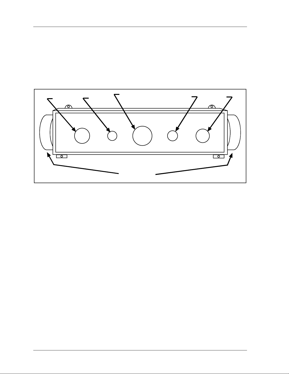
1126800 SmartPAC 2 with WPC Integration
• TOP STOP switch, which stops the ram at the top of stroke during continuous
operation.
• LEFT/RIGHT SELECT key switch for the ONE HAND trip mode, which is
located on the bottom of the Operator Station (optional).
RUN/
INCH
PRIOR ACT
switch
PRIOR
ACT
PAL M TIM E
LED
PALM
TIME
EMERGENCY STOP /
RESET
switch
EMERGENCY
STOP
RESET
RUN / INCH
palm switches
MUTE
LED
MUTE
TOP STOP
TOP
STOP
OPERATOR STATION
switch
RUN/
INCH
Figure 1 - 2. Illustration of Operator Station
• Dual-monitored Safety Valve, which controls the air flow that operates the clutch and
brake of the press. DSVs are available in many popular sizes.
• System air pressure switches, which monitor the system air pressure.
• Shadow light curtain: The Shadow light curtain is a presence-sensing device that places
an infrared light field between the point-of-operation and the operator. When something
enters the sensing field and a light beam is blocked, the object is detected and the press is
immediately stopped.
The standard WPC package is designed to be used with a Shadow light curtain. However,
you can purchase WPC without a light curtain. In this version, the control enclosure does
not have a MODE SELECT switch, and WPC will only operate in the TWO HAND
mode.
Shadow light curtain is optional for two-hand mode, but is required for point-of-operation
guarding if WPC is used with a foot switch or in the one-hand mode. WPC tests up to
two Shadow inputs every time the press is started and stopped.
Page 6 Chapter 1 Introduction to SmartPAC 2

SmartPAC 2 with WPC Integration 1126800
WPC Options
Optional components also available with WPC include:
• Counterbalance air pressure switch works the same as the clutch air pressure switch.
However, this switch is used with the counterbalance air supply. It is required by OSHA
regulations on presses with counterbalances.
• One-hand Control is a low-force switch that can be used with any Wintriss
Clutch/Brake Control (WPC) with one hand and single stroke mode. A Shadow light
curtain must be used with One-hand Control for guarding the point of operation. The
One-hand Control switch can be mounted on or near the press and allows the press
operator to cycle the press without using the operator station. To start the press, the
operator just presses the button as part of his normal hand motion after loading a part.
One-hand Control can be used in “light curtain break” mode. In this mode, the operator
must press the One-hand control button within eight seconds after removing his hands
from the light curtain. Otherwise the press will not start.
For complete information about One-hand Control, see Chapter 2 for installation and
Chapter 6 for operation.
• Foot Switch frees up the operator's hands for increased, fully guarded protection and
productivity. (Shadow light curtain is required with Foot Switch.)
• Bar Mode Control allows operators and setup personnel to bar the press by hand for die
setting and adjustment (recommended for smaller capacity presses, of 65-ton capacity or
less).
• Automatic Single Stroke (External Trip) allows equipment like a feeder to signal WPC
to start the press for one stroke. This is useful when your press must stop after every
stroke until a feed is completed. The Automatic Single Stroke function allows the feeder
to signal WPC to start the press when the feed is complete.
Refer to Chapters 2 and 4 for more information.
• Continuous on Demand allows an external signal to cause WPC to start operating the
press in continuous mode.
• Multiple Operator Stations and Dual Operator Select Control:
NOTICE
Use light curtains in addition to multiple operator stations for best personnel safeguarding
You can have an unlimited number of operator stations as part of your WPC system.
However, up to two operator stations can be connected directly to WPC. More than two
operator stations need to be connected to WPC via a Dual Operator Selection Control
(Wintriss part no. 4152100).
Introduction to SmartPAC 2 Chapter 1 page 7

1126800 SmartPAC 2 with WPC Integration
When more than two Operator Stations are required, the Dual Operator Select Control allows two operator stations to be connected to one of WPC's operator station inputs, and
allows the operator to select either operator station or both.
See Chapter 2 to install and Chapter 6 to use Multiple Operator Stations.
DANGER!
HAZARDS EXPOSED BY NON-WORKING OPERATOR STATION
Safeguard the point of operation exposed by the non-working operator station when using
multiple operator stations. This exposed area near a disabled operator station must be
properly guarded.
• Ensure that guarding is properly installed to prevent access to the machine over, under or
around any guarding device.
Failure to comply with these instructions will result in death or serious injury.
• WPC display configurations: You may have ordered WPC without an enclosure or
with enclosure minus display and switches. If so, be sure to follow the instructions in
Section 2 of Chapter 2 which detail installing WPC without an enclosure. Then refer to
one or more of the display configuration options in this section to complete the
installation including: panel mount clock display with selector switches (no enclosures);
clock display kit (without panel) with selector switches; and second clock (either panel
mount display or clock display kit).
How SmartPAC 2 Works
The Resolver Lets SmartPAC 2 and WPC Know Where the Crankshaft Is
SmartPAC 2 with WPC is connected to a resolver mounted on the press which turns one to
one (1:1) with the crankshaft. Similar to an electrical generator, the resolver has windings
inside and works on the principle of inductance. As the resolver turns, the amplitude and the
phase of its two outputs varies. These signals are interpreted by SmartPAC 2's electronics to
determine the correct crankshaft angle at every point in the stroke. SmartPAC 2 converts the
analog signal from the resolver at any point in its rotation to a number that is the position of
the resolver (and press crankshaft) in degrees.
SmartPAC 2 with WPC Makes Various Decisions Simultaneously
SmartPAC 2 with WPC has powerful counter and brake monitoring capabilities.
SmartPAC 2 with optional programmable cam and die protection capabilities can make
instantaneous decisions for up to 16 cams and/or 16 sensors respectively. Because
SmartPAC 2 is microprocessor-based, it can monitor or control all these different functions
during a press stroke even for very high speed presses. Additionally, it saves these settings
for up to 200 tools.
Page 8 Chapter 1 Introduction to SmartPAC 2
 Loading...