


Honeywell Process Solutions
STT700 Series HART/DE Option
User’s Manual
34-TT-25-18
Revision 1
July 2017

Page ii STT700 Series HART/DE Option User’s Manual Revision 1
Copyrights, Notices and Trademarks
© Copyright 2017 by Honeywell, Inc.
Revision 1, July 2017
While the information in this document is presented in good faith and believed to be
accurate, Honeywell disclaims any implied warranties of merchantability and fitness for a
particular purpose and makes no express warranties except as may be stated in the written
agreement with and for its customers. In no event is Honeywell liable to anyone for any
indirect, special, or consequential damages. The information and specifications in this
document are subject to change without notice.
Honeywell, TDC 3000, SFC, SmartLine, PlantScape, Experion PKS, and TotalPlant are
registered trademarks of Honeywell International Inc. Other brand or product names and
service marks are the property of their respective owners.
Honeywell Process Solutions
1250 W Sam Houston Pkwy S
Houston, TX 77042

Revision 1 STT700 Series HART/DE Option User’s Manual Page iii
About This Manual
This manual provides the details of programming Honeywell STT700 SmartLine Temperature
Transmitters for applications involving HART versions 5, 6, and 7 and Honeywell’s Digitally
Enhanced (DE) communication protocols. For installation, wiring, and maintenance information
refer to the STT700 SmartLine Temperature Transmitter User Manual, document number
#34-TT-25-17.
The configuration of your transmitter depends on the mode of operation and the options selected
for it with respect to operating controls, displays and mechanical installation. Details for
operations involving the Honeywell Multi-Communication MC Toolkit (MCT404) are provided
only to the extent necessary to accomplish the tasks-at-hand. Refer to the associated MC Toolkit
User Manual, document # 34-ST-25-50 (MCT404) for complete details. The “Reference” section
in the front matter of this manual lists document titles and numbers.
The STT700 SmartLine Temperature Transmitter can be digitally integrated with one of two
Honeywell systems:
Experion PKS: you will need to supplement the information in this document with the data and
procedures in the Experion Knowledge Builder.
Honeywell’s TotalPlant Solutions (TPS): you will need to supplement the information in this
document with the data in the PM/APM SmartLine Transmitter Integration Manual, which is
supplied with the TDC 3000 book set. (TPS is the evolution of the TDC 3000).
Release Information
STT700 Series HART/DE Option User Manual, Document # 34-TT-25-18 (this document)
Rev. 1 July 2017 1st Release
References
The following list identifies publications that may contain information relevant to the information
in this document.
STT700 SmartLine Temperature Transmitter Quick Start Installation Guide, # 34-TT-25-19
STT700 SmartLine Temperature Transmitter w/ HART/DE Comms Safety manual, 34-TT-25-20
STT700 SmartLine Temperature Transmitter User manual, # 34-TT-25-17
FDM Offline Configuration User’s manual, # 34-CT-25-01.
MC Toolkit (MCT404) User Manual, Document # 34-ST-25-50
PM/APM SmartLine Transmitter Integration manual, # PM 12-410
STT700 Series Temperature, Transmitter, Agency IS Control Drawing, #50133855
MC Toolkit Modem Code Download Instruction Manual, Document # 34-ST-25-33

Page iv STT700 Series HART/DE Option User’s Manual Revision 1
Patent Notice
The Honeywell STT700 SmartLine Temperature Transmitter family is covered by one or more of the
following U. S. Patents: 5,485,753; 5,811,690; 6,041,659; 6,055,633; 7,786,878; 8,073,098; and other
patents pending.
Support and Contact Information
For Europe, Asia Pacific, North and South America contact details, see back page or refer to the
appropriate Honeywell Solution Support web site:
Honeywell Corporate www.honeywell.com
Honeywell Process Solutions www.honeywellprocess.com
SmartLine Temperature https://www.honeywellprocess.com/smartline-temperature/
Training Classes http://www.automationccollege.com
Telephone and Email Contacts
Area
Organization
Phone Number
United States and
Canada
Honeywell Inc.
1-800-343-0228 Customer Service
1-800-423-9883 Global Technical Support
Global email
Support
Honeywell Process
Solutions
ask-ssc@honeywell.com

Revision 1 STT700 Series HART/DE Option User’s Manual Page v
Contents
1 STT700 Physical and Functional Characteristics ........................................................................... 8
1.1 Overview ................................................................................................................................ 8
1.2 Features and Options .............................................................................................................. 9
1.2.1 Physical Characteristics ................................................................................................ 10
1.2.2 Functional Characteristics ............................................................................................ 11
1.3 STT700 SmartLine Transmitter Nameplate ......................................................................... 11
1.4 Safety Certification Information ........................................................................................... 12
1.5 Transmitter Adjustments ...................................................................................................... 12
1.6 EU Meters Options ............................................................................................................... 12
2 Communication Modes ................................................................................................................ 13
2.1 Overview .............................................................................................................................. 13
2.2 Digitally Enhanced (DE) Mode Communication ................................................................. 13
2.3 HART Mode Communication .............................................................................................. 14
3 Configuration Tools and Interfaces .............................................................................................. 15
3.1 Overview .............................................................................................................................. 15
3.2 Pre-requisites ........................................................................................................................ 15
3.3 Application Design, Installation, Startup, and Operation ..................................................... 15
3.3.1 Organization ................................................................................................................. 15
3.4 MC Toolkit Participation ...................................................................................................... 16
3.4.1 MC Toolkit Software Applications .............................................................................. 16
3.4.2 Configuration Databases .............................................................................................. 16
3.4.3 Configuration ................................................................................................................ 16
3.4.4 MC Toolkit Transmitter Electrical/Signal Connections ............................................... 17
4 DE Transmitter Configuration ...................................................................................................... 18
4.1 Configuration Personnel Requirements ................................................................................ 18
4.2 MC Toolkit Software Application Overview ....................................................................... 18
4.3 DE Transmitter Online Configuration .................................................................................. 19
4.3.1 Uploading a Transmitter Configuration ....................................................................... 19
4.3.2 Device Information Configuration ............................................................................... 21
4.3.3 General Configuration Parameters ............................................................................... 22
4.3.4 DE-Specific Configuration Parameters ........................................................................ 23
4.3.5 DE Auxiliary Configuration ......................................................................................... 24
4.3.6 DE Monitor Status ........................................................................................................ 24
4.3.7 Saving the Configuration to File .................................................................................. 26
4.3.8 DE Online Configuration Summary ............................................................................. 27
4.4 DE Transmitter Offline Configuration ................................................................................. 27
4.4.1 Overview ...................................................................................................................... 27
4.4.2 DE Offline File Management ....................................................................................... 27
4.4.3 Save to a File ................................................................................................................ 28
4.4.4 Downloading in DE Offline Mode ............................................................................... 28
4.4.5 DE Offline Parameterization ........................................................................................ 28
5 HART Transmitter Configuration ................................................................................................ 29
5.1 Overview .............................................................................................................................. 29
5.1.1 Personnel Requirements ............................................................................................... 29

Page vi STT700 Series HART/DE Option User’s Manual Revision 1
5.2 Overview of FDC Homepage .............................................................................................. 30
5.2.1 Settings ......................................................................................................................... 31
5.2.2 Manage DDs ................................................................................................................ 32
5.2.3 Online configuration ................................................................ .................................... 34
5.2.4 Offline configuration .................................................................................................... 34
5.2.5 Online Configuration Overview ................................................................................... 34
5.2.6 Overview of Device Homepage ................................................................................... 35
5.2.7 Tabs on the Device Home page ................................................................................... 36
5.2.8 Using FDC for various device operations .................................................................... 38
5.2.9 Device Configuration and Parameter Descriptions ...................................................... 40
5.2.10 Procedure to Enter the Transmitter Tag ....................................................................... 57
5.2.11 Selecting the Process Variable (PV) Unit of Temperature Measurement .................... 57
5.2.12 Setting PV URV, and LRV Values .............................................................................. 58
5.2.13 Setting Range Values for Applied Temperature .......................................................... 58
5.2.14 Saving device history ................................................................................................... 59
5.2.15 Exporting device history records to FDM .................................................................... 60
5.2.16 Exporting device history records to DocuMint ............................................................ 61
5.2.17 Custom Views .............................................................................................................. 61
5.2.18 Offline Configuration ................................................................................................... 63
6 DE Calibration ............................................................................................................................. 66
6.1 Overview .............................................................................................................................. 66
6.2 Calibration Recommendations ............................................................................................. 66
6.3 Test Equipment Required for Calibration ............................................................................ 66
6.4 Analog Output Signal Calibration ........................................................................................ 67
6.5 Calibrating Range Using the MC Toolkit ............................................................................ 69
6.6 Conditions for Input Calibration .......................................................................................... 69
6.7 Input Calibration Procedures Description ............................................................................ 69
6.8 Input Calibration Procedure ................................................................................................. 70
6.8.1 Correct Input at the Lower Range Value (LRV) .......................................................... 70
6.8.2 Correct Input at URV ................................................................................................... 71
6.9 DE Output Calibration ......................................................................................................... 73
6.9.1 Output Calibration Preparation .................................................................................... 73
6.10 Manually Setting the Process Variable Range ..................................................................... 76
6.11 Procedure to Reset Calibration ............................................................................................ 79
7 HART Calibration ........................................................................................................................ 81
7.1 About This Section .............................................................................................................. 81
7.1.1 About Calibration ......................................................................................................... 81
7.1.2 Equipment Required .................................................................................................... 81
7.1.3 Input Calibration Procedure ......................................................................................... 82
7.1.4 Correct Input at Sensor 1 / 2 Calibration High Point ................................................... 84
7.2 Analog Output Signal Calibration ........................................................................................ 87
7.3 Calibrating Analog Inputs .................................................................................................... 88
7.3.1 Correcting the Low Calibration Point .......................................................................... 88
7.3.2 Correcting the High Calibration Point ......................................................................... 89
7.3.3 Resetting Calibration .................................................................................................... 89
7.3.4 STT700 Calibration Records ....................................................................................... 90

Revision 1 STT700 Series HART/DE Option User’s Manual Page vii
8 HART Advanced Diagnostics ...................................................................................................... 91
8.1 About This Section ............................................................................................................... 91
8.2 Advanced Diagnostics .......................................................................................................... 91
8.2.1 Transmitter Install Date ................................................................................................ 91
8.2.2 PV Tracking Diagnostics .............................................................................................. 92
8.2.3 Cold Junction Tracking ................................................................................................ 95
8.2.4 CT Tracking Diagnostics .............................................................................................. 97
8.2.5 Installation and Device Life ......................................................................................... 98
8.2.6 Operating Voltage Diagnostics ..................................................................................... 98
8.2.7 Power Up Diagnostics .................................................................................................. 99
9 Troubleshooting and Maintenance ............................................................................................. 100
9.1 HART Diagnostic Messages .............................................................................................. 100
9.2 DE Diagnostic Details ........................................................................................................ 102
10 - DTMs ....................................................................................................................................... 104
10.1 Introduction ........................................................................................................................ 104
10.2 Components ........................................................................................................................ 104
10.3 Downloads .......................................................................................................................... 104
10.4 Procedure to Install and Run the DTM ............................................................................... 104
10.5 STT700 Dashboard ............................................................................................................. 105
10.6 STT700 Online Parameterization ....................................................................................... 105
10.6.1 Device Health ............................................................................................................. 106
10.6.2 Device Icon / Honeywell Logo ................................................................................... 106
10.6.3 Process Variables ........................................................................................................ 106
10.6.4 Shortcuts ..................................................................................................................... 106
10.7 Basic Configuration Page ................................................................................................... 107
10.7.1 Device Information ..................................................................................................... 107
10.7.2 Model Number ............................................................................................................ 107
10.7.3 Device Assembly ........................................................................................................ 107
10.8 STT700 Offline Parameterization ...................................................................................... 108
11 HART DD Binary File Format Compatibility Matrix ................................................................ 109
Glossary .............................................................................................................................................. 110

Page viii STT700 Series HART/DE Option User’s Manual Revision 1
List of Figures
Figure 1 – STT700 HART Temperature Transmitter module ............................................................. 10
Figure 2 – STT700 DE Temperature Transmitter module ................................................................... 10
Figure 3 – Nameplate on the side of the transmitter ............................................................................ 11
Figure 4 –Typical STT700 Nameplate ................................................................................................. 12
Figure 5 – DE Mode Value Scaling ..................................................................................................... 13
Figure 6 – HART Point-to-Point and Multi-drop Value Scaling ......................................................... 14
Figure 7 – MC Toolkit-Transmitter Electrical/Signal Connections ..................................................... 17
Figure 8 – FDC Homepage .................................................................................................................. 30
Figure 9 – Device Homepage............................................................................................................... 35
Figure 10 – Analog Output Calibration Test Setup ............................................................................. 67
Figure 11 – Input Calibration Connections .......................................................................................... 70
Figure 12 – Output Calibration Test Connections ............................................................................... 73
Figure 13 – DE Analog Mode Scaling and Test Connections ............................................................. 74
Figure 14 – Setup to Manually Set the PV LRV and URV ................................................................. 76
List of Tables
Table 1 – Features and Options ............................................................................................................. 9
Table 2 – Available EU Meter Characteristics .................................................................................... 12
Table 3 – Device Information Parameters ........................................................................................... 21
Table 4 – General Configuration Parameters ....................................................................................... 22
Table 5 – DE Configuration Parameters .............................................................................................. 23
Table 6 – Monitor Parameters .............................................................................................................. 25
Table 7 – FDC homepage elements ..................................................................................................... 30
Table 8 – Device health status ............................................................................................................. 35
Table 9 – HART Transmitter Parameters ............................................................................................ 40
Table 10 – Basic Configuration ........................................................................................................... 40
Table 11 – Advanced Configuration .................................................................................................... 43
Table 12 – Monitor .............................................................................................................................. 51
Table 13 – Calibration Records ........................................................................................................... 90
Table 14 – Viewing Advanced Diagnostics ......................................................................................... 91
Table 15 – PV Tracking ....................................................................................................................... 92
Table 16 – Cold Junction Tracking ...................................................................................................... 95
Table 17 – Core Temperature Diagnostics .......................................................................................... 97
Table 18 – Installation and Device Life Diagnostics ........................................................................... 98
Table 19 – Operating Voltage Diagnostics .......................................................................................... 98
Table 20 – Power Up Diagnostics ........................................................................................................ 99
Table 21 – HART Diagnostic Messages ............................................................................................ 100
Table 22 – DE Critical and Non-Critical Diagnostic Details ............................................................. 102
1 STT700 Physical and Functional Characteristics
1.1 Overview
This section is an introduction to the physical and functional characteristics of Honeywell’s STT700
SmartLine Temperature Transmitter.
Revision 1 STT700 Series HART/DE Option User’s Manual Page 9
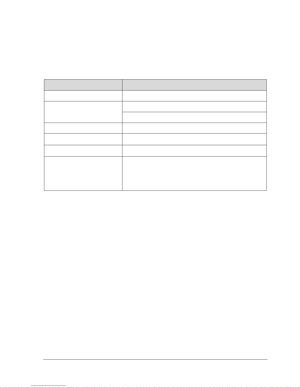
1.2 Features and Options
The STT700 SmartLine Temperature Transmitter is available in a variety of models for measuring
thermocouples, RTD and millivolts and ohm sensor types. Table 1 lists the protocols, human machine
interface (HMI), materials, approvals, and mounting bracket options for the STT700.
Table 1 – Features and Options
Feature/Option
Standard/Available Options
Communication Protocols
HART version 7, Digitally Enhanced (DE)
Human-Machine Interface (HMI)
Options
No Display
EU Meter
Calibration
Two-point
Approvals (See Appendix C for
details.)
ATEX, CSA, FM, IECx
Mounting Brackets
Pipe mounting and wall mounting brackets in carbon steel and
316 stainless steel.
Integration Tools
Smart Field Communicator (SFC),
SmartLine Configuration Tool kit (SCT),
MC Toolkit (MCT404),
Experion,
Field Device Manager (FDM) and Device Type Manager (DTM)
Page 10 STT700 Series HART/DE Option User’s Manual Revision 1
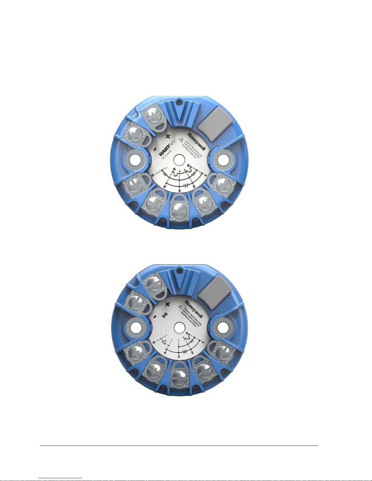
1.2.1 Physical Characteristics
As shown in Figure 1 and Figure 2, the STT700 is packaged in a single module. The elements in this
module are connected to the process sensors, measure the process variables, respond to setup
commands and execute the software and protocol for the different temperature measurement types.
Figure 1 – STT700 HART Temperature Transmitter module
Figure 2 – STT700 DE Temperature Transmitter module

Revision 1 STT700 Series HART/DE Option User’s Manual Page 11
1.2.2 Functional Characteristics
The transmitter measures process temperature and outputs a signal proportional to the measured
process variable (PV). Available output communication protocols include analog 4 to 20 mA,
Honeywell Digitally Enhanced (DE) and HART protocols.
To set up and make adjustments, the Honeywell Multi-Communication (MC) Toolkit (not supplied
with the transmitter) can facilitate setup and adjustment procedures in the case of HART and DE.
Certain adjustments can be made through an Experion Station or a Universal Station if the transmitter
is digitally integrated with Honeywell’s Experion or TPS/TDC 3000 control system for HART and DE
transmitters.
1.3 STT700 SmartLine Transmitter Nameplate
The transmitter nameplate mounted on the side of the transmitter module (see Figure 4) lists the model
number, physical configuration, electronics options, accessories, certifications, and manufacturing
specialties (see Figure 4).
Figure 3 – Nameplate on the side of the transmitter

Page 12 STT700 Series HART/DE Option User’s Manual Revision 1
Figure 4 is an example of a typical STT700 temperature nameplate. The model number format consists
of a key number with several table selections.
Figure 4 –Typical STT700 Nameplate
The transmitter type can be identified from the key number. The letter in the third digit represents one
of these basic transmitter types:
T = Temperature
For a complete selection breakdown, refer to the Specification and Model Selection Guide provided as
a separate document.
1.4 Safety Certification Information
The approvals name plate contains information and service marks that disclose the transmitter
compliance information. Refer to Appendix A in the STT700 SmartLine Transmitters User’s manual,
document number 34-TT-25-17 for details.
1.5 Transmitter Adjustments
For HART and DE, the Honeywell MC Toolkit or other third-party hand-held can make any
adjustments to a STT700 SmartLine Temperature Transmitter. Alternately, certain adjustments can be
made through the Experion or Universal Station, if the transmitter is digitally integrated with a
Honeywell Experion or TPS system.
1.6 EU Meters Options
The STT700 SmartLine Temperature Transmitter is offered with an EU Meter or no display options, see Table 2
Table 2 – Available EU Meter Characteristics
EU Meter
Compatibility for replacement of existing STT250 installations
360o rotation in 90o increments
Standard units of measurement: °F, °C, °R, K, Ω, mV & %
Key I II III IV V VI VII VIII
STT700 - _ _ - _ _ _ - _ _ _ _ _ _ - _ _ _ _ - _ _ _ - _ - _ _, _ _, _ _ - 00000
Revision 1 STT700 Series HART/DE Option User’s Manual Page 13
2 Communication Modes
2.1 Overview
The STT700 SmartLine Temperature Transmitter can be configured for operation with Honeywell’s
Digitally Enhanced (DE) communication protocol and HART version 7 communication. This manual
addresses the processes to configure and calibrate a transmitter for DE and HART communication.
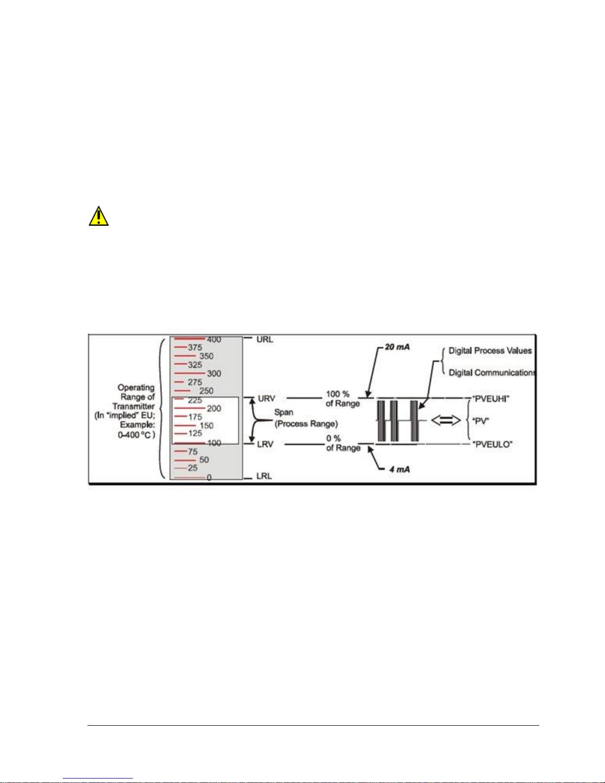
2.2 Digitally Enhanced (DE) Mode Communication
Although it is unnecessary to put a control loop in manual mode before communicating
with a transmitter operating in DE mode, caution is required if there is potential for error in
identifying the operating mode.
In DE mode, the PV is available for monitoring and control purposes.
Much of the operation in the Digitally Enhanced (DE) mode is similar to that of analog operation. The
essential characteristics of DE mode operation are shown in Figure 5.
Figure 5 – DE Mode Value Scaling
As indicated at the right of Figure 5, output values of process variables, as well as communications are
transferred to a receiving device digitally. The digital coding is Honeywell proprietary, which requires
the use of DE-capable Honeywell control equipment.
The use of DE mode offers several advantages:
Process Safety: Unlike analog mode, communications devices do not bump the PV value.
Accuracy: Requires less maintenance.
Digital communication: Relatively immune to small variations in circuit resistance or supply
voltage.
Facilitates Maintenance Tasks: Honeywell control systems include operating displays that
enable direct communication with transmitters operating in DE mode.
Page 14 STT700 Series HART/DE Option User’s Manual Revision 1
2.3 HART Mode Communication
When using MCT404, but before connecting to a HART transmitter, verify that the FDC
application is used and not the MC Toolkit application. When using the MC Toolkit application,
the MCT404 is set for DE communications, where the current amplitude can bump process
variables in either point-to-point or in the multi-drop mode in HART.
Transmitters with HART capability have features that vary among manufacturers and
with the characteristics of specific devices. The FDC software application executing on
the MCT404 supports the HART Universal, Common Practice and Device Specific
Commands which are implemented in the Honeywell transmitters.
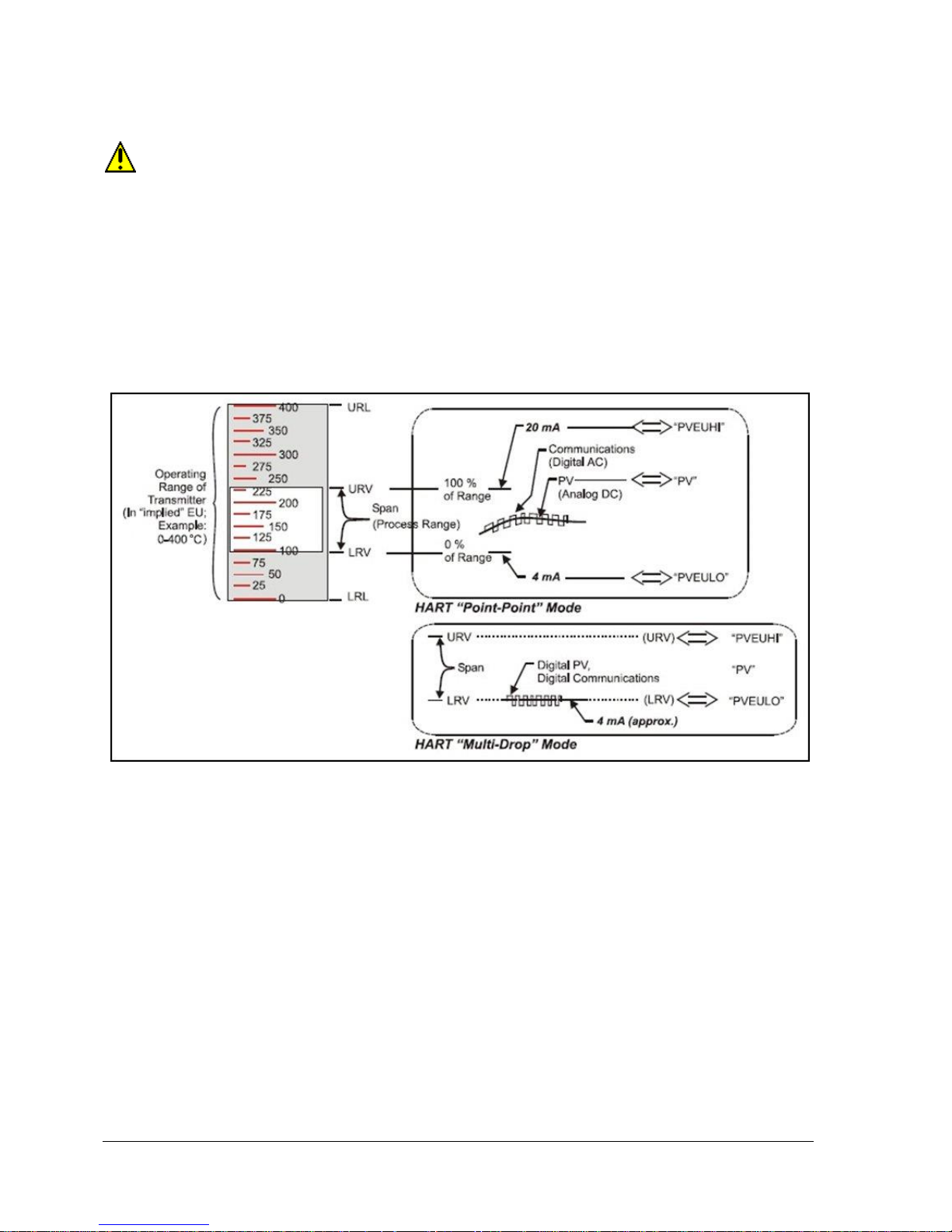
As indicated in Figure 6, the output of a transmitter configured for HART protocol includes two
primary modes:
Figure 6 – HART Point-to-Point and Multi-drop Value Scaling
Point-to-Point Mode, in which one transmitter is connected via a two-conductor, 4-20 mA
current loop to one receiver.
Multi-Drop Mode, in which several transmitters are connected through a two-conductor
network to a multiplexed receiver device.
In point-to-point mode, the value of the primary Process Variable (PV) is represented by a 4-20 mA
current loop, and is almost identical to that of a transmitter operating in analog mode. Additionally,
one device can reside in analog output mode when it is configured in multi-drop. In this case, however,
the analog signal is modulated by Frequency Shift Keying (FSK), using frequencies and current
amplitude that do not affect analog sensing at the receiver. The accuracy of the analog value must be
precisely controlled for accurate sensing. HART communication will not bump process variables.
In multi-drop mode, up to 16 transmitters in HART 5 (addresses 0-15) and up to 64 transmitters in
HART6/7 (addresses 0-63) can exist on the two-conductor network.

Revision 1 STT700 Series HART/DE Option User’s Manual Page 15
3 Configuration Tools and Interfaces
3.1 Overview
This section describes the tools and interfaces involved in configuring a new STT700 SmartLine
Temperature Transmitter for HART or DE communication operation. The information in this section
also applies to adjusting the configuration of a transmitter that has been in operation and updating one
that is currently in operation.
3.2 Pre-requisites
The information and procedures in this manual are based on the assumption that personnel performing
configuration and calibration tasks are fully qualified and knowledgeable in the use of the Honeywell
MC Toolkit MCT404. The reference to MC Toolkit, Toolkit and MCT404 are used interchangeably as
MCT404 is the model name for the Honeywell MC Toolkit product.
Furthermore, we assume that the reader is intimately familiar with the STT700 SmartLine
Temperature Transmitter and thoroughly experienced in the type of process application targeted for
transmitter deployment. Therefore, detailed procedures are supplied only in so far as necessary to
ensure satisfactory completion of configuration tasks.
3.3 Application Design, Installation, Startup, and Operation
The STT700 SmartLine Temperature Transmitters User’s Manual, document number 34-TT-25-17,
provides the details for Application Design, Installation and Startup, Operation, Configuration tools,
Maintenance and Calibration.
3.3.1 Organization
This information in this section is arranged in the following sequence:
MC Toolkit participation in STT700 transmitter setup and configuration:
1. Physical circuit connections
2. Application components
3. Configuration for analog, DE and HART operation
STT700 transmitter
1. Health indications
2. Ability to be configured and operate in a process system

Page 16 STT700 Series HART/DE Option User’s Manual Revision 1
3.4 MC Toolkit Participation
Before using the MC Toolkit, be sure that you are aware of the potential consequences of
each procedure, and that you use appropriate safeguards to avoid possible problems. For
example, if the transmitter is an element in a control loop, the loop needs to be put in manual
mode, and alarms and interlocks (i.e., trips) need to be disabled, as appropriate, before starting
a procedure.
3.4.1 MC Toolkit Software Applications
The MC Toolkit has two software applications that apply to the STT700 SmartLine Temperature
Transmitter, which are:
Field Device Configurator (FDC). This application is used for configuring, calibrating,
monitoring, and diagnosing HART devices. FDC conforms to the IEC 61804-3 EDDL
(Electronic Data Description Language) standard specification. The FDC application is an open
solution that supports devices with a registered device description (DD) file compatible with
HART Communication Foundation (HCF) requirements.
MC Toolkit. This application is used for configuring, calibrating, monitoring, and diagnosing
Honeywell Digitally Enhanced (DE) devices.
Details for working with the MC Toolkit are provided in the MC Toolkit User Manual, document #34ST-25-50 (MCT404). In subsequent sections of this manual, explicit operating instructions are
provided only in so far as necessary to complete required tasks and procedures.
3.4.2 Configuration Databases
The MC Toolkit is used to establish and/or change selected operating parameters in a transmitter
database.
3.4.3 Configuration
Configuration can be accomplished both online and offline with the transmitter powered up and
connected to the MC Toolkit. Online configuration immediately changes the transmitter operating
parameters. For offline configuration, transmitter operating characteristics are entered into the MC
Toolkit memory for subsequent downloading to a transmitter.
When you set up or configure a transmitter, it can take up to 30 seconds for the value to
be stored in it. If you change a value and transmitter power is interrupted before the change
is copied to nonvolatile memory, the changed value will not be moved to nonvolatile memory.
Revision 1 STT700 Series HART/DE Option User’s Manual Page 17
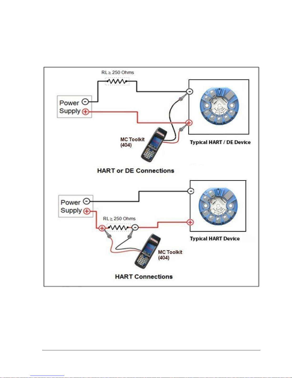
3.4.4 MC Toolkit Transmitter Electrical/Signal Connections
Figure 7 displays how to connect the MC Toolkit directly to the terminals of a HART or DE
transmitter (top) and a HART-only transmitter (bottom).
Figure 7 – MC Toolkit-Transmitter Electrical/Signal Connections

Page 18 STT700 Series HART/DE Option User’s Manual Revision 1
4 DE Transmitter Configuration
4.1 Configuration Personnel Requirements
The configuration processes in this section reflect the assumption that you will use the Honeywell MC
Toolkit configuration tool to configure an STT700 SmartLine Temperature Transmitter. The MC
Toolkit application is used to configure Honeywell ST 3000 and SmartLine Pressure Transmitter, STT
3000 Smart Temperature Transmitters, as well as the STT700 SmartLine Temperature Transmitter.
Throughout, the term transmitter means the STT700 SmartLine Temperature Transmitter.
The other tools that support DE transmitter configuration are the SmartLine Configuration Toolkit
(SCT 3000), Experion PKS, and Smart Field Communicator (SFC).
4.2 MC Toolkit Software Application Overview
Each new STT700 SmartLine Temperature Transmitter is shipped from the factory with a basic
configuration installed. This basic configuration must be edited or revised to meet the requirements of
your process system.
The MC Toolkit application supports both online and offline configuration.
Online operation establishes communication with a DE transmitter for the following tasks:
o Upload a transmitter database.
o Configure transmitter parameters.
o Calibrate a transmitter.
o Execute diagnostics.
o Save a configuration to a file.
Offline operation allows to the selection of a basic template, the ability to edit the parameters
and the ability download to a transmitter after establishing communication with it. Parameter
updates can also be saved in a file without actually downloading them to the transmitter.
Specific operating details for the MC Toolkit displays are provided in “MC Toolkit Application
Software Display Conventions,” of the MC Toolkit User Manual, (document number #34-ST-25-50
for MCT404) for the following:
Navigation
The MC Toolkit Menu Bar
File Menu
Modem Menu
Help Menu
Data Entry and Display
Revision 1 STT700 Series HART/DE Option User’s Manual Page 19
4.3 DE Transmitter Online Configuration
Online configuration consists of establishing communication between the MC Toolkit and a
transmitter configured for DE communication. Each transmitter has a configured database, whether
new from the factory, a spare, or one to be reconfigured. In any case, the MC Toolkit application is
used to upload the existing configuration from the transmitter for review and editing.
4.3.1 Uploading a Transmitter Configuration
1. Connect a DE transmitter to the MC Toolkit. Be sure that both devices have power applied.
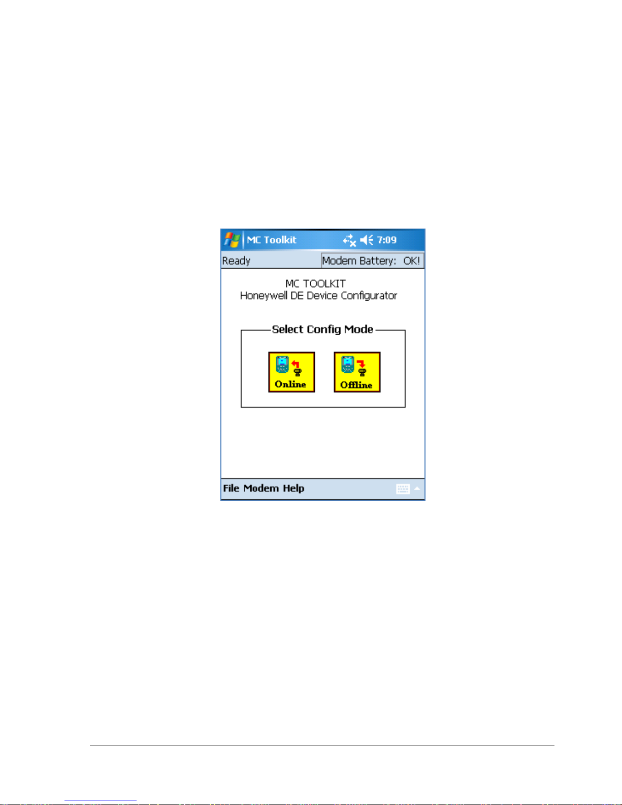
2. Start the MC Toolkit application by selecting Start / MC Toolkit on the MC Toolkit /
MCT404/202. The MC TOOLKIT Home page will be displayed, see below figure.
3. Select the Online button, and establish communication between the Toolkit and the
transmitter.
4. When the warning message for connecting to a DE device appears, select OK.
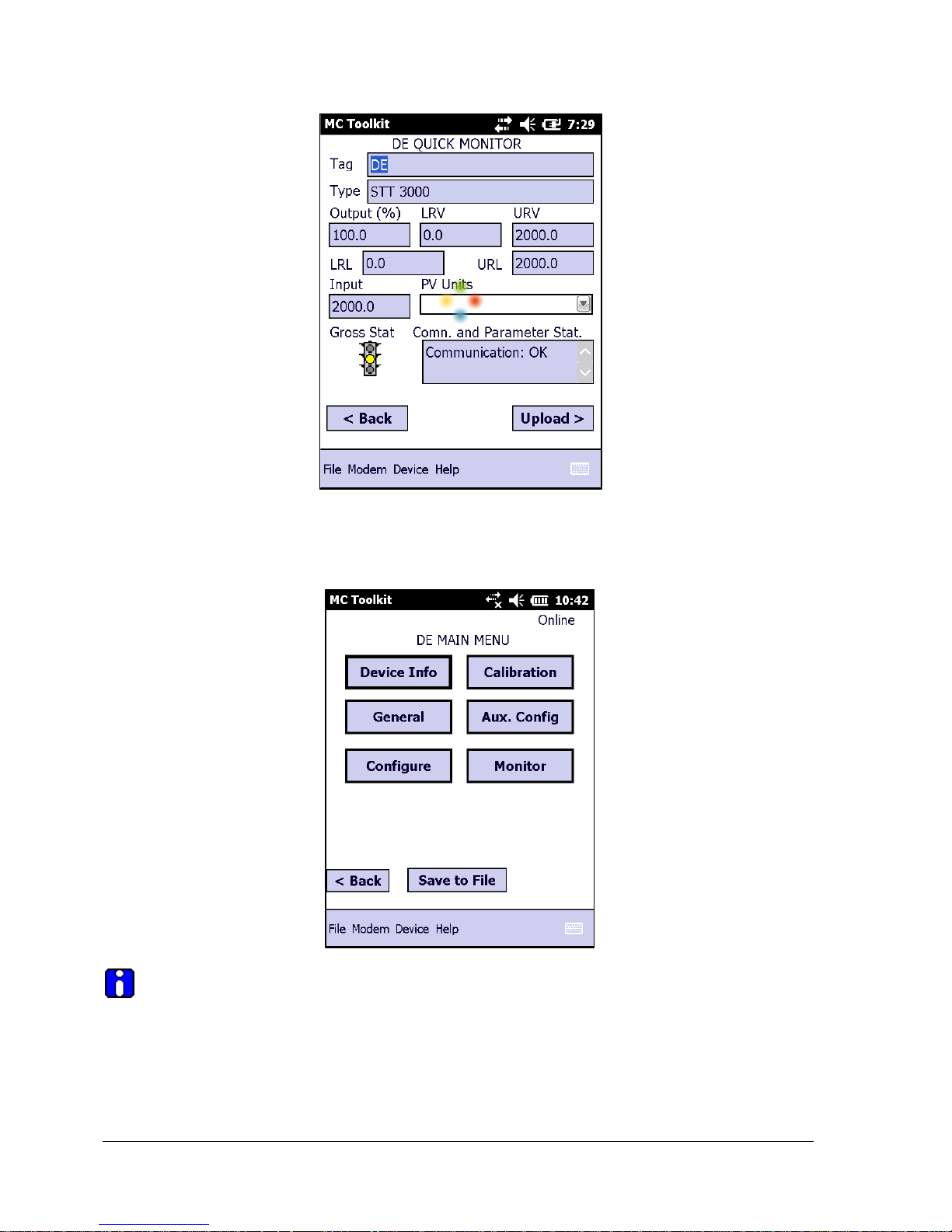
5. Process and respond to the three warning pop-ups as appropriate, and then select OK in the
Put loop in Manual… pop-up. The QUICK MONITOR box will be displayed. Typical Quick
Monitor dialog is shown below (note that Type will be shown as STT3000).
Page 20 STT700 Series HART/DE Option User’s Manual Revision 1
6. Select Upload. A progress bar will be displayed on the QUICK MONITOR box, and when the
upload is complete, the DE MAIN MENU will be displayed. Typical DE Main Menu dialog is
shown below.
A confirmation request message will be displayed if you select <Back for a transmitter
that was previously set to Output Mode during calibration, and was not subsequently cleared.
If you confirm the message (Yes answer), the display will exit the DE MAIN MENU.
Revision 1 STT700 Series HART/DE Option User’s Manual Page 21
4.3.2 Device Information Configuration
In this and subsequent procedures, the notations R for read only and R/W for read/write are used to
indicate if a parameter can be edited.
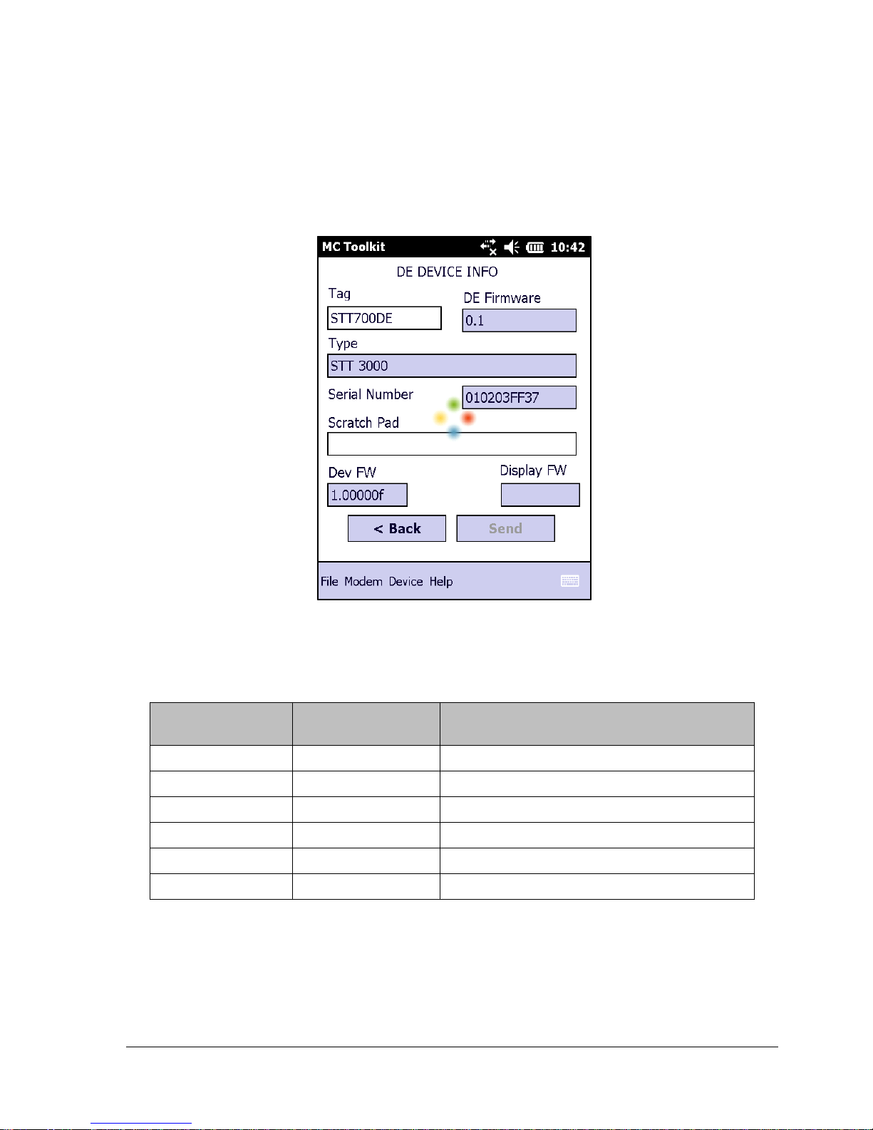
1. On the DE MAIN MENU, select Device Info. The DE DEVICE INFO box will be displayed.
Typical DE device information with type and firmware detail is shown here.
2. DE DEVICE INFO parameter attributes and details, Table 3.
Table 3 – Device Information Parameters
Parameter
Read (R) or
Read/Write (R/W)
Configuration Details
Tag ID
R/W
User ID up to 8 alphanumeric characters.
Type
R
Manufacturer’s device type identifier
DE Firmware
R
Manufacturer’s firmware version identifier
PROM ID Number
R
PROM ID Number
Scratch Pad
R/W
Up to 32 alphanumeric characters
Dev FW
R
DE PWA firmware version
3. Select the Back button to go back to the DE MAIN MENU.
Page 22 STT700 Series HART/DE Option User’s Manual Revision 1
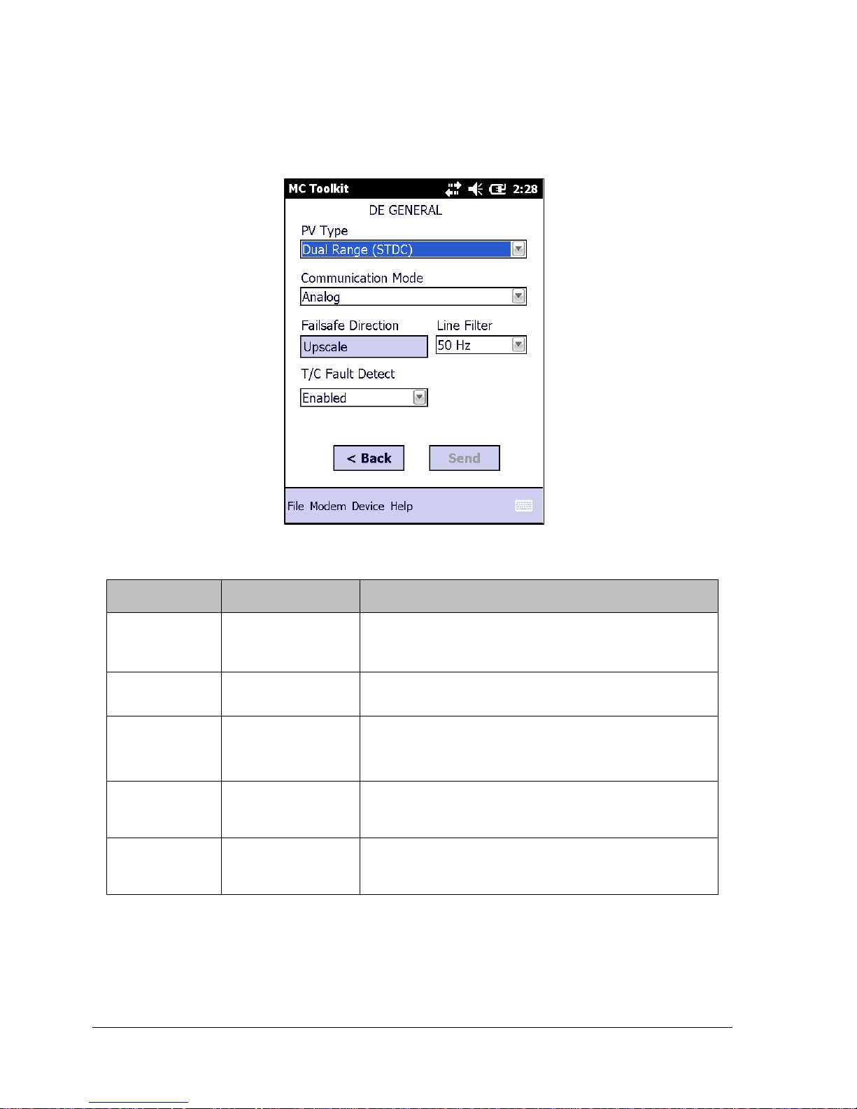
4.3.3 General Configuration Parameters
Select the General Button on the DEVICE MAIN MENU page, and configure parameters.
See Table 4.
Table 4 – General Configuration Parameters
Parameter
Read (R) or
Read/Write (R/W)
Configuration Details
PV Type
R/W
Dual Range Smart Transmitter Digital Communications
(STDC) or Single Range or Single Range with
secondary variable (SV).
Communication
Mode
R/W
Analog, DE 4-byte, or DE 6-byte
FS Direction
(HART only)
R
Failsafe (FS) direction: upscale or downscale, switch
non-selectable on the electronics module. See the
STT700 SmartLine Temperature Transmitter User
Manual for details.
Line Filter
(HART only)
R
Non-selectable: 50hz or 60hz.
T/C Fault
Detect
R/W
Select: Enabled or Disabled.
Select the Back button to go back to the DE MAIN MENU.
Revision 1 STT700 Series HART/DE Option User’s Manual Page 23
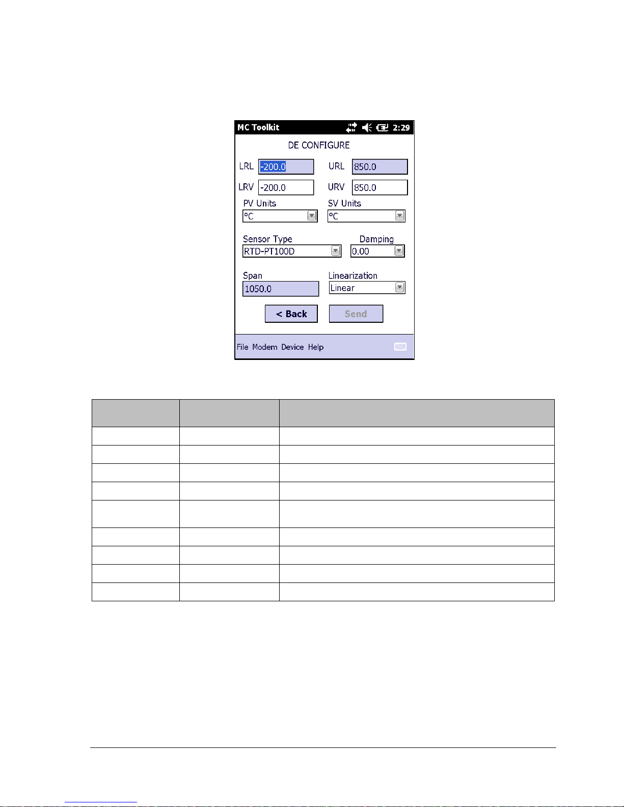
4.3.4 DE-Specific Configuration Parameters
Select the Configure button, and configure parameters. See Table 5.
Table 5 – DE Configuration Parameters
Parameter
Read (R) or
Read/Write (R/W)
Configuration Details
LRL R Lower Range Limit, Floating Point
URL
R
Upper Range Limit, Floating Point
LRV
R/W
Lower Range Value, Floating Point
URV
R/W
Upper Range Value, Floating Point
PV Units
R/W
Process Variable Units: scaling value selection;
SV Units
R/W
Secondary Variable scaling units: oC or oF
Sensor Type
R/W
Sensor type used in the Transmitter*
Damping
R/W
Select digital noise reduction; (see note below)
Span
R
Process Range: URV – LRV, Floating Point
*A dual input model cannot be configured as a single input model.
Select the Back button to go back to the DE MAIN MENU.
4.3.4.1 Notes on Damping (Digital Noise Reduction)
You can adjust the damping time to reduce output noise. In general, set damping to the smallest value
reasonable for your process.
Page 24 STT700 Series HART/DE Option User’s Manual Revision 1
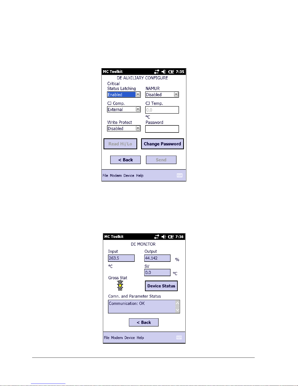
4.3.5 DE Auxiliary Configuration
The DE auxiliary configuration menu contains latching status enable/disable option and also CJ
compensation selection. When selecting External for the CJ Comp , CJ Temp 0.0 is only applicable
choice; the temperature does not vary.
.
Select the Back button to go back to the DE MAIN MENU.
4.3.6 DE Monitor Status
The DE Monitor menu shows Input PV value, Output percentage value, SV value and Device status
option. Table 6 lists the status parameters and their details.
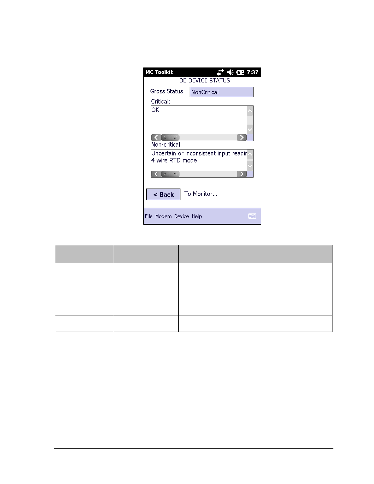
Revision 1 STT700 Series HART/DE Option User’s Manual Page 25
The Device status menu shows Critical, Non critical status along with gross status information.
Table 6 – Monitor Parameters
Parameter
Read (R) or
Read/Write (R/W)
Configuration Details
Input
R
Sensor input in EU
Output
R
Loop output as a percent of Span
SV R Secondary Variable in SV EU
Gross Status
R
Gross Transmitter Status. Select the Monitor menu
Device Status button to display device status.
Communication
Status
R
Refer to the “Messages and Diagnostic Codes”
section of the MCT404/202 Toolkit manual.
Select the Back button to go back to the DE MAIN MENU.
Page 26 STT700 Series HART/DE Option User’s Manual Revision 1
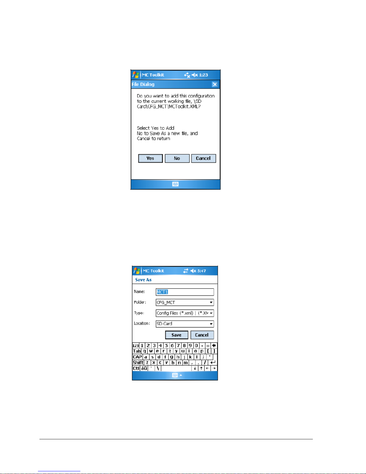
4.3.7 Saving the Configuration to File
1. Display the DE MAIN MENU, and select the Save to File button. The File Dialog will be
displayed.
2. Save the configuration as described below. As a reminder, please refer to the MC Toolkit User
Manual, #34-ST-25-50 (MCT404), for complete procedural details.
a. Select Cancel to return to the DE MAIN MENU, and abort saving the configuration.
b. Select Yes to add the configuration to the current working file, and return the display
to the DE MAIN MENU.
c. Select No to save to a different file; the Save As screen will be displayed.
d. The default location and folder are set to SD Card and CFG_MCT. However, you
can type in a new name for the file; the default name is New1.
e. After entering the file name, select the Save button to display the DE MAIN MENU.

Revision 1 STT700 Series HART/DE Option User’s Manual Page 27
4.3.8 DE Online Configuration Summary
This concludes the process of configuring an STT700 DE transmitter online. For best operational
results, calibrate the transmitter according to the DE calibration in section 6 of this document.
4.4 DE Transmitter Offline Configuration
4.4.1 Overview
This section summarizes the features, and processes for configuring an STT700 SmartLine
Temperature Transmitter set for DE operation offline. Refer to the MC Toolkit User Manual,
#34-ST-25-50 (MCT404), “Offline Configuration” for complete procedural details.
After starting the MC Toolkit application, selecting the Offline button provides access to the
following configuration features:
DE Offline File Management – Open an XML file, select a saved configuration for the
selected device and edit the parameters.
Save to File – Save the parameters back to the file.
Download – Download the current offline configuration to a device after establishing
connection.
The MC Toolkit can process more than one device type or model. For the purposes of this section, the
term transmitter refers to the STT700 SmartLine Temperature Transmitter.
4.4.2 DE Offline File Management
Offline configuration allows you to select a basic template, edit its parameter content, and download it
to a transmitter after establishing communication. Parameter updates can also be saved in a file
without actually downloading to a transmitter.
The MCT404/202 Toolkit is shipped with the two files: MCToolkit.xml and TEMPLMCT.xml:
The MCToolkit.xml file consists of default configurations for all the supported DE
transmitters. The available configurations can be updated and saved back to this file.
The TEMPLMCT.XML is a template file. The contents of this template file cannot be
edited; however, the template can be saved under a different file name. The contents of the
newly named file can be edited.
DE offline file management provides general, configuration, and parameter options. General options
provide for communication serial port selection of COM1 through COM8. However, the current
configuration of the MCToolkit (also known as Pocket PC) provides only COM1; the other seven
serial port designations are reserved for future expansion.
Communication Port Setting = COM1
Offline configuration options provide for confirmation before saving a changed configuration file.
Denying confirmation results in having the changes discarded.

Page 28 STT700 Series HART/DE Option User’s Manual Revision 1
In addition to file saving confirmation, DE offline file management provides access to three parameter
sets for review and editing:
Parameter Set 1 consists of the description of transmitter according to bus type, device type,
serial and model number, and the manufacturer.
Parameter Set 2 permits entering/editing the values for the LRL, URL, LRV, URV, PV
Units, Damping, SV Units, Line Filter frequency, Sensor Type, and the output characterization
selection.
Parameter Set 3 is oriented primarily to the Honeywell SmartLine Temperature Transmitter
models for monitoring purposes.
4.4.3 Save to a File
Saving to a file in offline mode will let you add an edited configuration to a working file. Alternately,
if you decide not to save an edited configuration to the current file, you can select a new location and
file name for it. The default location and folder for saving configurations is SD Card and CFG MCT.
The default name of a new configuration is New1, which you can change for your needs.
4.4.4 Downloading in DE Offline Mode
Downloading a file to a transmitter from the Toolkit requires a communicating connection between the
two units. Serial communication is established when you select DOWNLOAD to Device from the
Toolkit Select Device menu. When the download completes, confirmation will be required to affirm
that the configuration for the transmitter is to be saved.
4.4.5 DE Offline Parameterization
Section 5.7 “Offline Configuration,” of the MC Toolkit User Manual, #34-ST-25-50 (MCT404),
contains a list of the basic STT700 SmartLine Temperature Transmitter parameters for DE offline
operation.

Revision 1 STT700 Series HART/DE Option User’s Manual Page 29
5 HART Transmitter Configuration
5.1 Overview
Each new STT700 Temperature Transmitter configured for HART protocol is shipped from the factory
with a basic configuration database installed. This basic configuration database must be edited or
revised to meet the requirements of your process system. The process in this section assumes that you
will use the Field Device Communicator (FDC) application for HART configuration tasks. The FDC
application provides the facilities for the online and offline configuration of transmitters operating with
HART protocol
Online configuration requires that the transmitter and MC Toolkit are connected and communication
between the two have been established. Online configuration provides a set of functions with which to
perform various operations on a HART communication network through an active communication
link. These operations primarily include configuration, calibration, monitoring, and diagnostics.
Typically, these operations could be realized through various constructs exposed by the Device
Description (DD) file. In addition, the FDC application provides some functions for convenient
execution of these functions.
Offline configuration refers to configuring a device when the device is not physically present or
communicating with the application. This process enables you to create and save a configuration for a
device, even when the device is not there physically. Later when the device becomes available with
live communication, the same configuration can be downloaded to the device. This feature enables you
to save on device commissioning time and even helps you to replicate the configuration in multiplicity
of devices with lesser efforts. Currently, FDC does not support creating offline configuration.
However, it supports importing of offline configuration from FDM R310 or later versions. The
configurations thus imported can be downloaded to the device from FDC.
The following are the tasks that you need to perform for importing offline configuration in FDC
application software and then downloading it to the device.
1. Create offline configuration template in FDM
2. Save the configuration in FDM in FDM format.
3. Import the offline configuration in FDC
4. Download the offline configuration to the device
Note: For details on creating and using offline configuration, refer to section Offline configuration inFDM Offline Configuration User’s Manual, 34-CT-25-01.
5.1.1 Personnel Requirements
The information and procedures in this section are based on the assumption that the person
accomplishing configuration tasks is fully qualified and knowledgeable on the use of the MC Toolkit
and is intimately familiar with the STT700 SmartLine Temperature Transmitter. Therefore, detailed
procedures are supplied only in so far as necessary to ensure satisfactory configuration. The other
HART configuration ools are Honeywell Experion in conjunction with FDM, DTMs running on FDM
or PACTware, and Emerson 375/475.
Page 30 STT700 Series HART/DE Option User’s Manual Revision 1
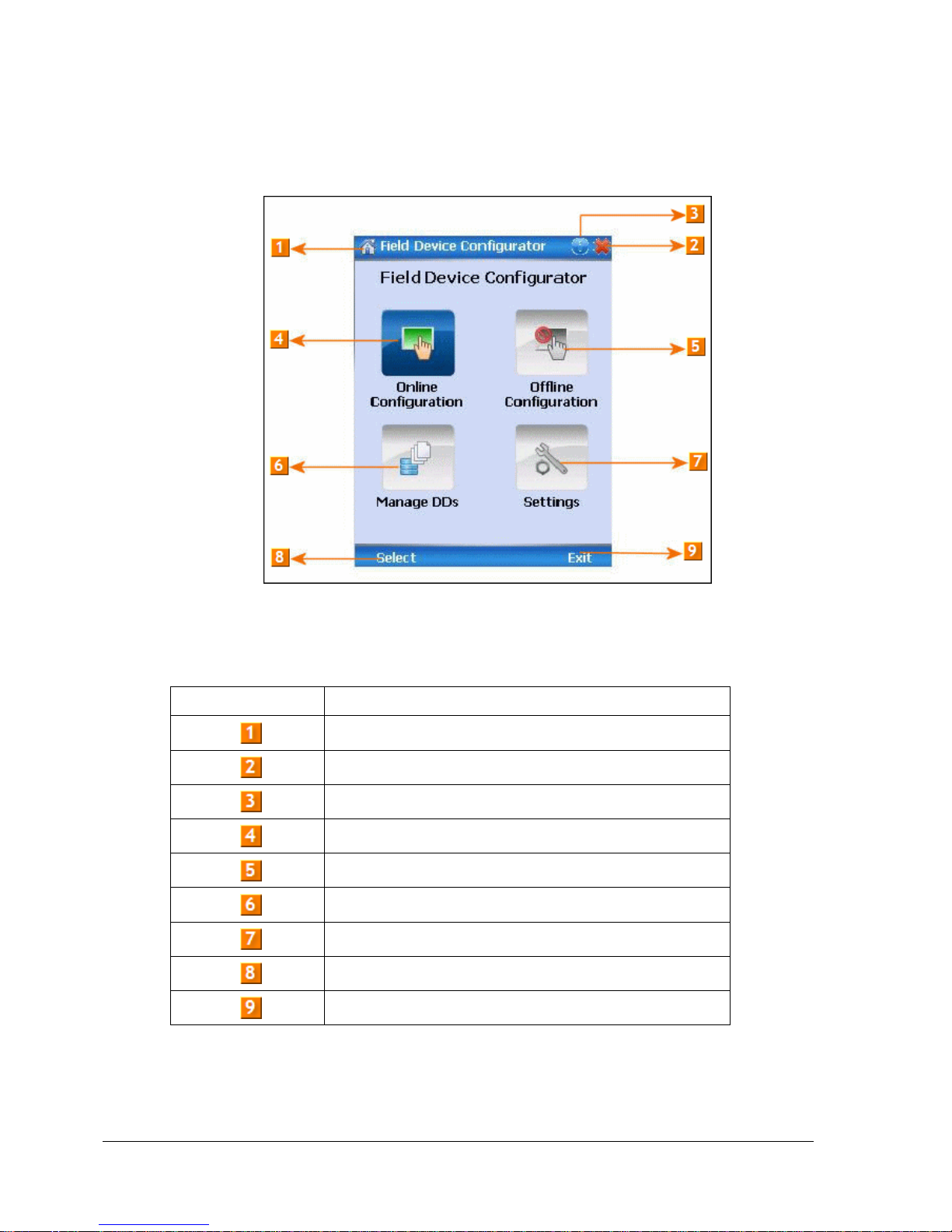
5.2 Overview of FDC Homepage
The FDC homepage consists of links for Online Configuration, Offline Configuration, Manage DDs,
and Settings. See figure 8 below.
Figure 8 – FDC Homepage
Table 7 lists the items that appear on the FDC homepage and their descriptions.
Table 7 – FDC homepage elements
Items
Description
Screen title.
Tap to quit FDC.
Tap to view the application information.
Tap to navigate to Online Configuration screen.
Tap to navigate to Offline configuration screen.
Tap to navigate to Manage DDs screen.
Tap to navigate to Settings screen.
Tap to select the highlighted menu option.
Tap to quit FDC.
Note: To select a particular option in FDC you can either select the option and then tap Select or you
can directly double-tap the option.
 Loading...