

Honeywell SmartLine ST700 Installation Manual
SmartLine Pressure Transmitter ST 700 Basic
Quick Start Safety Installation Guide
34-ST-25-57, Revision 2, November 2018
March 2018 Quick Start Safety Installation Guide 1
This document provides descriptions and
procedures for the Quick Installation of
Honeywell’s ST 700 Basic SmartLine
Pressure Transmitter.
The ST 700 Basic SmartLine Pressure
Transmitter is available in a variety of
models for measuring Differential Pressure
(DP), Gauge Pressure (GP), and Absolute
Pressure (AP). For full details refer to the
manuals listed below for protocols, human
interface (HMI), Operation, Installation,
Configuration, Calibration, Maintenance,
Parts, Safety and Approvals etc. including
options.
Copyrights, Notices and Trademarks
Copyright 2018 by Honeywell
Revision 2, November 2018
Trademarks
SmartLine, ST 700 are U.S. registered
trademarks of Honeywell Inc.
HART® is trademark of the FieldComm
Group™
Table of Contents
Installation .................................................................................................................. 1
Mounting the Transmitter ........................................................................................... 1
Conduit Entry Plugs and Adapters ............................................................................. 3
Wiring Connections and Power Up ............................................................................ 4
Explosion-Proof Conduit Seal .................................................................................... 4
Trim the Transmitter ................................................................................................... 4
Set the Jumpers For HART ........................................................................................ 5
Configuration Guide ................................................................................................... 5
Appendix A. PRODUCT CERTIFICATIONS .............................................................. 5
Hazardous Locations Certifications ............................................................................ 7
Control Drawing ......................................................................................................... 8
Tables
Table 1 - Conduit Entry Plugs .................................................................................... 3
Table 2 - Conduit Adapters ........................................................................................ 3
Table 3 - Jumper Settings .......................................................................................... 5
Table 4 - Standard Display Menu ............................................................................... 5
Figures
Figure 1:Mounting Brackets ....................................................................................... 1
Figure 2: Angle Mounting Bracket .............................................................................. 1
Figure 3: LGP and LAP models.................................................................................. 2
Figure 4: Rotating Transmitter Housing ..................................................................... 2
Figure 5: Using level to mount transmitter .................................................................. 2
Figure 6: Flange mounting ......................................................................................... 2
Figure 7: Flush Mounting ........................................................................................... 3
Figure 8: Remote Seal mounting................................................................................ 3
Figure 9: Electronic Housing Conduit Entries ............................................................. 3
Figure 10: Two-wire power/current loop ..................................................................... 4
Figure 11: Terminal Block and Grounding Screw location ......................................... 4
Figure 12: Jumper Location HART ............................................................................ 5
Documentation
To access complete documentation, including language variants, scan
the QR code below using your smart phone/device or QR code scanner.
Go to the APP store for your free Smartphone QR scanner
Or you can follow the URL to access the online SmartLine HUB page.
The HUB page will contain direct links to open SmartLine product
documentation.
URL QR Code
https://hwll.co/SmartLineHUB
Installation
Evaluate the site selected for the Transmitter installation with respect to the process
system design specifications and Honeywell’s published performance characteristics
for your particular model.
Temperature extremes can affect display quality. The display can become unreadable
at temperature extremes; however, this is only a temporary condition. The display will
again be readable when temperatures return to within operable limits.
Mounting the Transmitter
Transmitter models, except flush mounts and those with integral flanges, can be
attached to a two-inch (50 millimeter) vertical or horizontal pipe using Honeywell’s
optional angle or flat mounting bracket; alternately you can use your own bracket.
Flush-mount models are attached directly to a process pipe or tank by a one-inch
weld nipple. Models with integral flanges are supported by the flange connection.
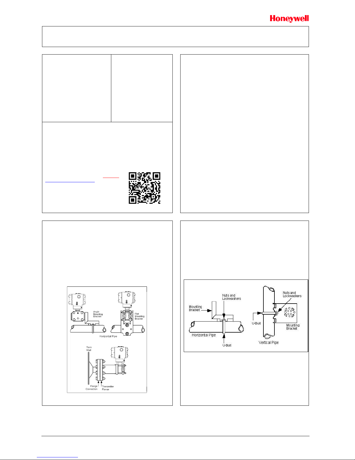
Typical Bracket mounted and Flange Mounted Installations
Figure 1:Mounting Brackets
Bracket Mounting
Optional mounting bracket, see Figure 2
Existing mounting bracket, see Figure 3
Rotate the transmitter housing, see Figure 4
Level a transmitter with small absolute or differential pressure spans, see Figure 5
Optional Mounting Bracket
Position the bracket on a 2-inch (50.8mm) and install “U” bolt around pipe and
through holes in bracket. Secure with nuts and lock washers provided.
Figure 2 Example - Angle mounting bracket secured to horizontal or vertical pipe.
Figure 2: Angle Mounting Bracket
November 2018 Quick Start Installation Guide 2
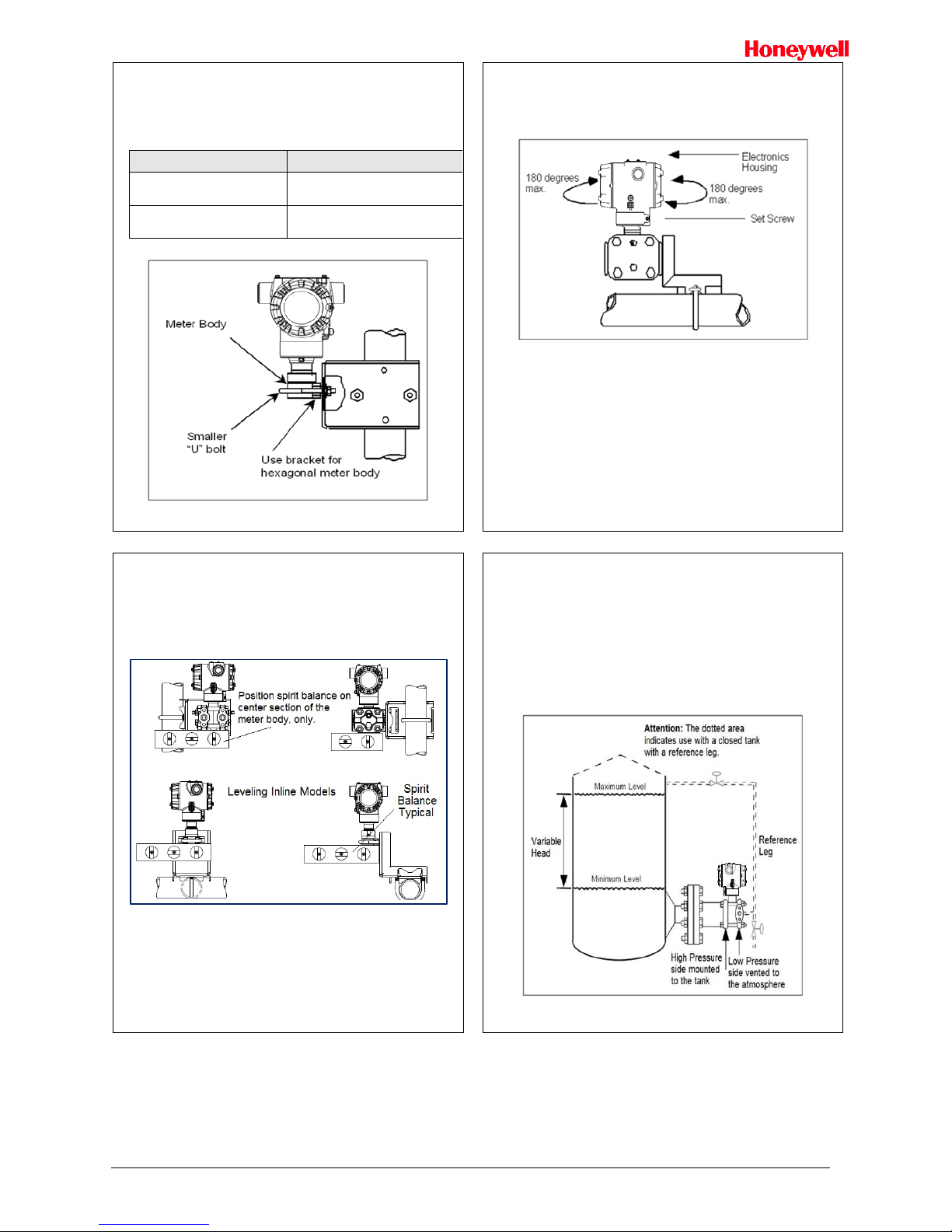
Existing Mounting Bracket
Align appropriate mounting holes in transmitter with holes in bracket and secure with
bolts and washers provided.
Note: If the meter body is hexagonal, you must use the additional bracket supplied.
If meter body is round, discard the bracket.
Example – LGP model transmitter mounted to optional angle mounting bracket.
If Transmitter is….
Then….
DP, Dual Head GP, Dual Head AP
and DP Remote Seals.
Use alternate mounting holes in end of
heads.
In-line GP and AP (LGP model) or
GP/AP Remote Seal
Use smaller “U” bolt provided to attach
meter body to bracket. See Figure 3.
Figure 3: LGP and LAP models
Rotating Transmitter Housing
Loosen set screw on outside neck of transmitter one full turn. Rotate Transmitter
housing in maximum of 180 degree increment in left or right direction from center to
position you require and tighten set screw (1.46 to 1.68Nm/13 to 15lb-in).
Figure 4 Example – Rotating Transmitter Housing.
Figure 4: Rotating Transmitter Housing
Leveling Transmitters with Small Absolute or Differential Pressure
Spans
Mounting position of these transmitters is critical due to the smaller transmitter spans.
To minimize these positional effects on calibration (zero shift), take the appropriate
mounting precautions that follow for the given transmitter model.
See Figure 5 for suggestions on how to level the transmitter using a spirit balance.
To perform a Zero Trim after leveling, refer to Trim the Transmitter on page 4.
Figure 5: Using level to mount transmitter
For transmitter models STA725 and STA72S you must ensure that the transmitter is
vertical when mounting it. You do this by leveling the transmitter side-to-side and
front-to-back.
Mount transmitter vertically to assure best accuracy. Position the spirit balance on the
pressure connection surface of AP body.
Flange Mounting
To mount a flange mounted transmitter model, bolt the transmitter’s flange to the flange
pipe on the wall of the tank.
On insulated tanks, remove enough insulation to accommodate the flange extension.
It is the End User’s responsibility to provide a flange gasket and mounting hardware that
are suitable for the transmitter’s service condition.
To prevent degradation of performance in Flush-Mounted Flanged Transmitters,
exercise care to ensure that the internal diameter of the flange gasket does not obstruct
the sensing diaphragm.
To prevent degradation of performance in Extended Mount Flanged Transmitters,
ensure that there is sufficient clearance in front of the sensing diaphragm body.
Figure 6: Flange mounting
November 2018 Quick Start Installation Guide 3
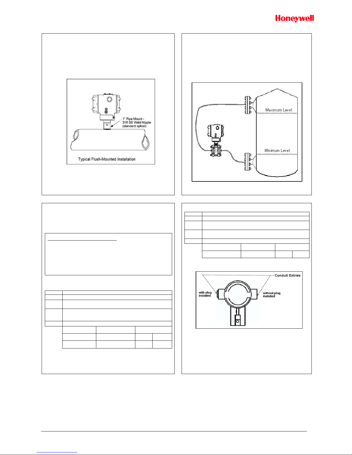
Flush Mounting
To mount a flush mounted transmitter model, cut a hole for a 1-inch standard pipe in the
tank or pipe where the transmitter is to be mounted. See Figure 7.
Weld the 1-inch mounting sleeve to the wall of the tank or to the hole cut on the pipe.
Insert the meter body of the transmitter into the mounting sleeve and secure with the
locking bolt. Tighten the bolt to a torque of 6.4Nm ±0.30Nm [4.7ft.-lbs. ±0.2ft.-lbs.]
Once the transmitter is mounted, the transmitter housing can be rotated to the desired
position. See Figure 7.
Figure 7: Flush Mounting
Remote Seal Mounting
Mount the transmitter at a remote distance determined by length of capillary tubing.
Note: The combination of tank vacuum and high pressure capillary head effect should
not exceed 9psi (300mm Hg) absolute.
On insulated tanks, remove enough insulation to accommodate the mounting sleeve.
Figure 8 Example – Typical Remote Seal Transmitter installation.
Note: For Sanitary 3-A installations, only mount the transmitter outside of the NonProduct Contact area where incidental contact with the process material is unlikely,
use a minimum capillary length of 1.5m (5ft.)
Figure 8: Remote Seal mounting
Conduit Entry Plugs and Adapters
Procedures
It is the User/Installer’s responsibility to install the Transmitters in accordance with
national and local code requirements. Conduit entry plugs and adapters shall be
suitable for the environment, shall be certified for the hazardous location when required
and acceptable to the authority having jurisdiction for the plant.
CONDUIT ENTRY PRECAUTIONARY NOTICE
THE CONDUIT/CABLE GLAND ENTRIES OF THIS PRODUCT ARE SUPPLIED
WITH PLASTIC DUST CAPS WHICH ARE NOT TO BE USED IN SERVICE.
IT IS THE USER’S RESPONSIBILITY TO REPLACE THE DUST CAPS WITH
CABLE GLANDS, ADAPTORS AND/OR BLANKING PLUGS WHICH ARE
SUITABLE FOR THE ENVIRONMENT INTO WHICH THIS PRODUCT WILL BE
INSTALLED. THIS INCLUDES ENSURING COMPLIANCE WITH HAZARDOUS
LOCATION REQUIREMENTS AND REQUIREMENTS OF OTHER GOVERNING
AUTHORITIES AS APPLICABLE.
Use the following procedures for installation:
Table 1 - Conduit Entry Plugs
Step
Action
1
Remove the protective plastic cap from the threaded conduit entry.
2
To ensure the environmental ingress protection rating on tapered
threads (NPT), a non-hardening thread sealant may be used.
3
Thread the appropriate size conduit plug (M20 or ½” NPT) into the
conduit entry opening. Do not install conduit entry plugs in conduit entry
openings if adapters or reducers will be used.
4
Tighten adapters according to the following table.
Description
Tool
Torque
M20 Conduit Entry
10mm Hex Wrench
32Nm
24Lb-ft
½” NPT Conduit
Entry
10mm Hex Wrench
32Nm
24Lb-ft
Table 2 - Conduit Adapters
Step
Action
1
Remove the protective plastic cap from the threaded conduit entry.
2
To ensure the environmental ingress rating on tapered threads (NPT),
a non-hardening thread sealant may be used.
3
Thread the appropriate size adapter (M20 or ½ NPT) into the conduit
entry opening
4
Tighten adapters according to the following table.
Description
Tool
Torque
½ to ¾ NPT Adapter
1 ¼” Wrench
32Nm
24Lb-ft
Figure 9: Electronic Housing Conduit Entries
Note. No plugs come installed in the housings. All housings come with temporary
plastic dust protectors (red) installed and are not certified for use in any installation
 Loading...