

Honeywell SmartDrive HVAC Installation Manual
Installation manual
Honeywell
SmartDrive HVAC
Variable Frequency Drive for
Heating, Ventilation and
Air conditioning applications

Honeywell • 0
INDEX
Document: DPD00487D
Version release date: 10.6.11
1. Safety ..................................................................................................................2
1.1 Danger ............................................................................................................................ 2
1.2 Warnings.........................................................................................................................3
1.3 Earthing and earth fault protection.................................................................................. 3
1.4 EMC levels...................................................................................................................... 4
1.4.1 Total Harmonic Distortion (THD)..................................................................................... 5
2. Receipt of delivery.............................................................................................6
2.1 Type designation code.................................................................................................... 7
2.2 Unpacking and lifting the drive........................................................................................ 8
2.2.1 Lifting frames MR8 and MR9 .......................................................................................... 8
2.3 Accessories................................................................................................................... 10
2.3.1 Size MR4 ...................................................................................................................... 10
2.3.2 Size MR5 ...................................................................................................................... 10
2.3.3 Size MR6 ...................................................................................................................... 11
2.3.4 Size MR7 ...................................................................................................................... 11
2.3.5 Size MR8 ...................................................................................................................... 12
2.3.6 Size MR9 ...................................................................................................................... 12
2.4 ‘Product modified’ sticker .............................................................................................. 13
3. Mounting...........................................................................................................14
3.1 Dimensions ...................................................................................................................14
3.2 Cooling.......................................................................................................................... 18
4. Power cabling ..................................................................................................20
4.1 UL standards on cabling ............................................................................................... 21
4.1.1 Cable dimensioning and selection ................................................................................ 21
4.2 Cable installation...........................................................................................................26
4.2.1 Frames MR4 to MR7..................................................................................................... 27
4.2.2 Frames MR8 and MR9.................................................................................................. 33
4.3 Installation in corner-grounded network........................................................................ 43
5. Control unit ......................................................................................................44
5.1 Control unit cabling ....................................................................................................... 45
5.1.1 Control cable sizing.......................................................................................................45
5.1.2 Control terminals and DIP switches .............................................................................. 46
5.2 I/O cabling and fieldbus connection.............................................................................. 49
5.2.1 Prepare for use through Ethernet ................................................................................. 49
5.2.2 Prepare for use through MS/TP.................................................................................... 51
5.2.3 RS485 cable data ......................................................................................................... 55
5.3 Changing the battery for Real Time Clock (RTC) ......................................................... 56
5.4 Galvanic isolation barriers............................................................................................. 57
6. Commissioning................................................................................................58
6.1 Commissioning of the drive........................................................................................... 59
6.2 Running the motor ........................................................................................................ 59
6.2.1 Cable and motor insulation checks............................................................................... 59
6.3 Installation in IT system ................................................................................................ 61
6.3.1 Frames MR4 to MR6..................................................................................................... 61
6.3.2 Frames MR7 and MR8.................................................................................................. 62
6.3.3 Frame MR9 ................................................................................................................... 63

Honeywell • 1
6.4 Maintenance ................................................................................................................. 65
7. Technical data..................................................................................................67
7.1 Drive power ratings ....................................................................................................... 67
7.1.1 Mains voltage 208-240 V .............................................................................................. 67
7.1.2 Mains voltage 380-480 V .............................................................................................. 68
7.1.3 Definitions of overloadability ......................................................................................... 69
7.2 Technical data...............................................................................................................70
7.2.1 Technical information on control connections............................................................... 73
SAFETY Honeywell • 2
1. SAFETY
This manual contains clearly marked cautions and warnings which are intended for your personal safety and to avoid any unintentional damage to the product or connected appliances.
Please read the information included in cautions and warnings carefully.
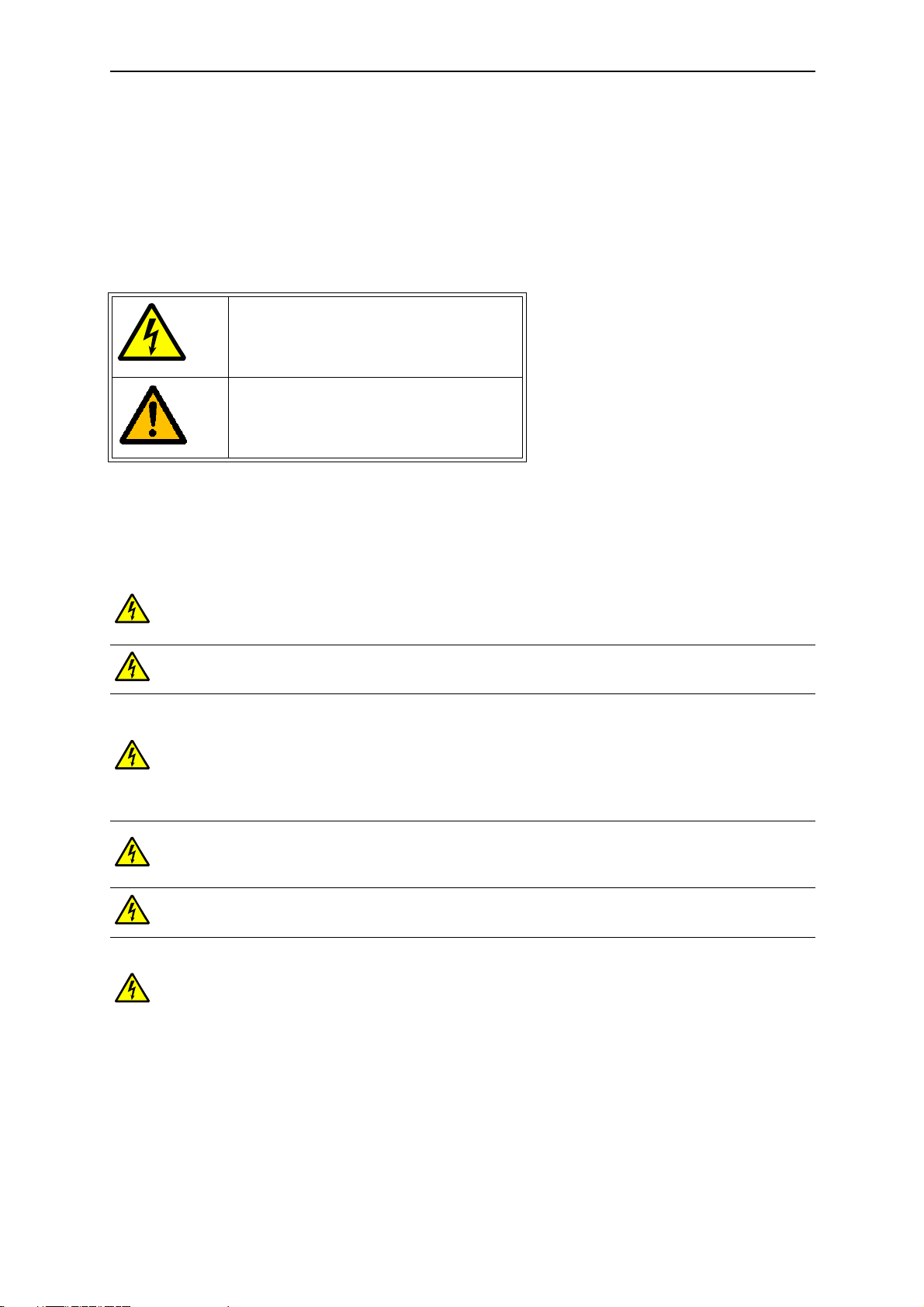
The cautions and warnings are marked as follows:
= DANGEROUS VOLTAGE!
= WARNING or CAUTION
Table 1. Warning signs
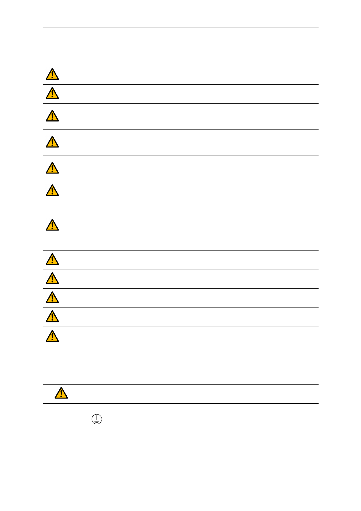
1.1 Danger
The components of the power unit of the drive are live when the drive is connected to mains potential. Coming into contact with this voltage is extremely
dangerous and may cause death or severe injury.
The motor terminals U, V, W and the brake resistor terminals are live when
the drive is connected to mains, even if the motor is not running.
After disconnecting the drive from the mains, wait until the indicators on the
keypad go out (if no keypad is attached see the indicators on the cover). Wait 5
more minutes before doing any work on the connections of the drive. Do not open
the cover before this time has expired. After expiration of this time, use a measuring equipment to absolutely ensure that no
absence of voltage before starting any electrical work!
The control I/O-terminals are isolated from the mains potential. However, the
relay outputs and other I/O-terminals may have a dangerous control voltage
present even when the drive is disconnected from mains.
Before connecting the drive to mains make sure that the front and cable covers
of the drive are closed.
During a coast stop (see the Application Manual), the motor is still generating
voltage to the drive. Therefore, do not touch the components of the drive before
the motor has completely stopped. Wait until the indicators on the keypad go out
(if no keypad is attached see the indicators on the cover). Wait additional 5 minutes before starting any work on the drive.
voltage is present.
Always ensure
1
Honeywell • 3 SAFETY
1.2 Warnings
The drive is meant for fixed installations only.
Do not perform any measurements when the drive is connected to the mains.
The touch current of the drives exceeds 3.5mA AC. According to standard
EN61800-5-1, a reinforced protective ground connection must be ensured.
See chapter 1.3.
Corner grounding is allowed for the drive types with the ratings from 72 A to 310
A at 380…480 V supply and from 75 A to 310 A at 208…240 V supply. Remember to change the EMC level by removing the jumpers. See chapter 6.3.
If the drive is used as a part of a machine, the machine manufacturer is
responsible for providing the machine with a supply disconnecting device (EN
60204-1).
Only spare parts delivered by Honeywell can be used.
At power-up, power brake or fault reset the motor will start immediately if the
start signal is active, unless the pulse control for Start/Stop logic has been
selected.
Futhermore, the I/O functionalities (including start inputs) may change if parameters, applications or software are changed.Disconnect, therefore, the motor if an
unexpected start can cause danger.
The motor starts automatically after automatic fault reset if the autoreset func-
tion is activated. See the Application Manual for more detailed information.
Prior to measurements on the motor or the motor cable, disconnect the
motor cable from the drive.
Do not touch the components on the circuit boards. Static voltage discharge
may damage the components.
Check that the EMC level of the drive corresponds to the requirements of your
supply network. See chapter 6.3.
In a domestic environment, this product may cause radio interference in which
case supplementary mitigation measures may be required.
1.3 Earthing and earth fault protection
CAUTION!
The drive must always be earthed with an earthing conductor connected to the earthing terminal marked with .
The touch current of the drive exceeds 3.5mA AC. According to EN61800-5-1, one or more of
the following conditions for the associated protective circuit shall be satisfied:
A fixed connection and

SAFETY Honeywell • 4
a) the protective earthing conductor shall have a cross-sectional area of at least 10
2
Cu or 16 mm2 Al.
mm
or
b) an automatic disconnection of the supply in case of discontinuity of the protective
earthing conductor. See chapter 4.
or
c) provision of an additional terminal for a second protective earthing conductor of the
same cross-sectional area as the original protective earthing conductor.
Minimum cross-sectional area of the corre-
Cross-sectional area of phase conductors (
2
]
[mm
S 16
16
S 35
S
35 <
The values above are valid only if the protective earthing conductor is m ade of the same metal as
the phase conductors. If this is not so, the cross-sectional area of the protective earthing conductor
shall be determined in a manner which produce s a conductance equivalent to that which results
from the application of this table.
S)
sponding protective earthing conductor
2
]
[mm
S
16
S/2
Table 2. Protective earthing conductor cross-section
The cross-sectional area of every protective earthing conductor which does not form a part of
the supply cable or cable enclosure shall, in any case, be not less than
2
• 2.5 mm
•4 mm
if mechanical protection is provided or
2
if mechanical protection is not provided. For cord-connected equipment, provisions shall be made so that the protective earthing conductor in the cord shall, in the
case of failure of the strain-relief mechanism, be the last conductor to be interrupted.
However, always follow the local regulations for the minimum size of the protective
earthing conductor.
NOTE: Due to the high capacitive currents present in the drive, fault current protective switches
may not function properly.
Do not perform any voltage withst and test s on any p art of the drive. There is a
certain procedure according to which the tests shall be performed. Ignoring this
procedure may result in damaged product.
1.4 EMC levels
SmartDrive HVAC inverters are divided into three classes according to the le vel of electromagnetic disturbances emitted, the requirements of a power system network and the installation
environment (see below). The EMC class of each product is defined in the type designation
code.
Category C1 (Honeywell EMC class C): Inverters of this class comply with the requirements
of category C1 of the product standard EN 61800-3 (2004). Category C1 ensures the best EMC
1

Honeywell • 5 SAFETY
characteristics and it includes converters the rated voltage of which is less than 1000V and
which are intended for use in the 1st environment. This EMC class is meant for highly sensitive
areas and can be sometimes required in installations in e.g. hospitals or airport control towers.
NOTE: The requirements of class C1 are fulfilled only as far as the conducted emissions are
concerned with an external EMC-filter.
Category C2 (Honeywell EMC class H): All Honeywell SmartDrive HVAC inverters comply
with the requirements of category C2 of the product standard EN 61800-3 (2004). Category C2
includes converters in fixed installations and the rated voltage of which is less than 1000V. The
category C2 inverters can be used both in the 1st and the 2nd environment. This category fulfills the requirements with normal installations in buildings.
IT networks (Honeywell EMC class T): Inverters of this class fulfil the product standard EN
61800-3 (2004) if intended to be used in IT systems. In IT systems, the networks are isolated
from earth, or connected to earth through high impedance to achieve a low leakage current.
NOTE: if inverters configured to IT network are used with other supplies, no EMC requirements
are complied with. SmartDrive HVAC inverters can be easily modified to the requirements of
the T-class. This class is very typical requirement also in installations in ships. Also the 230V
SmartDrive HVAC products can be ordered as ready configured to this class by adding a T to
the end of standard product code (HVAC230-xxx-xxT).
Environments in product standard EN 61800-3 (2004):
First environment: Environment that includes domestic premises. It also includes establishments directly connected without intermediate transformers to a low-voltage power supply network which supplies buildings used for domestic purposes.
NOTE: houses, apartments, commercial premises or offices in a residential building are examples of first environment locations.
Second environment: Environment that includes all establishments other than those directly
connected to a low-voltage power supply network which supplies buildings used for domestic
purposes.
NOTE: industrial areas, technical areas of any building fed from a dedicated transformer are
examples of second environment locations.
1.4.1 Total Harmonic Distortion (THD)
This equipment complies with IEC 61000-3-12 provided that the short-circuit power S
SC
is
greater than or equal to 120 at the interface point between the user’s supply and the public system. It is the responsibility of the installer or user of the equipment to ensure, by consultation
with the distribution network operator if necessary, that the equipment is connected only to a
supply with a short-circuit power S
greater than or equal to 120.
SC
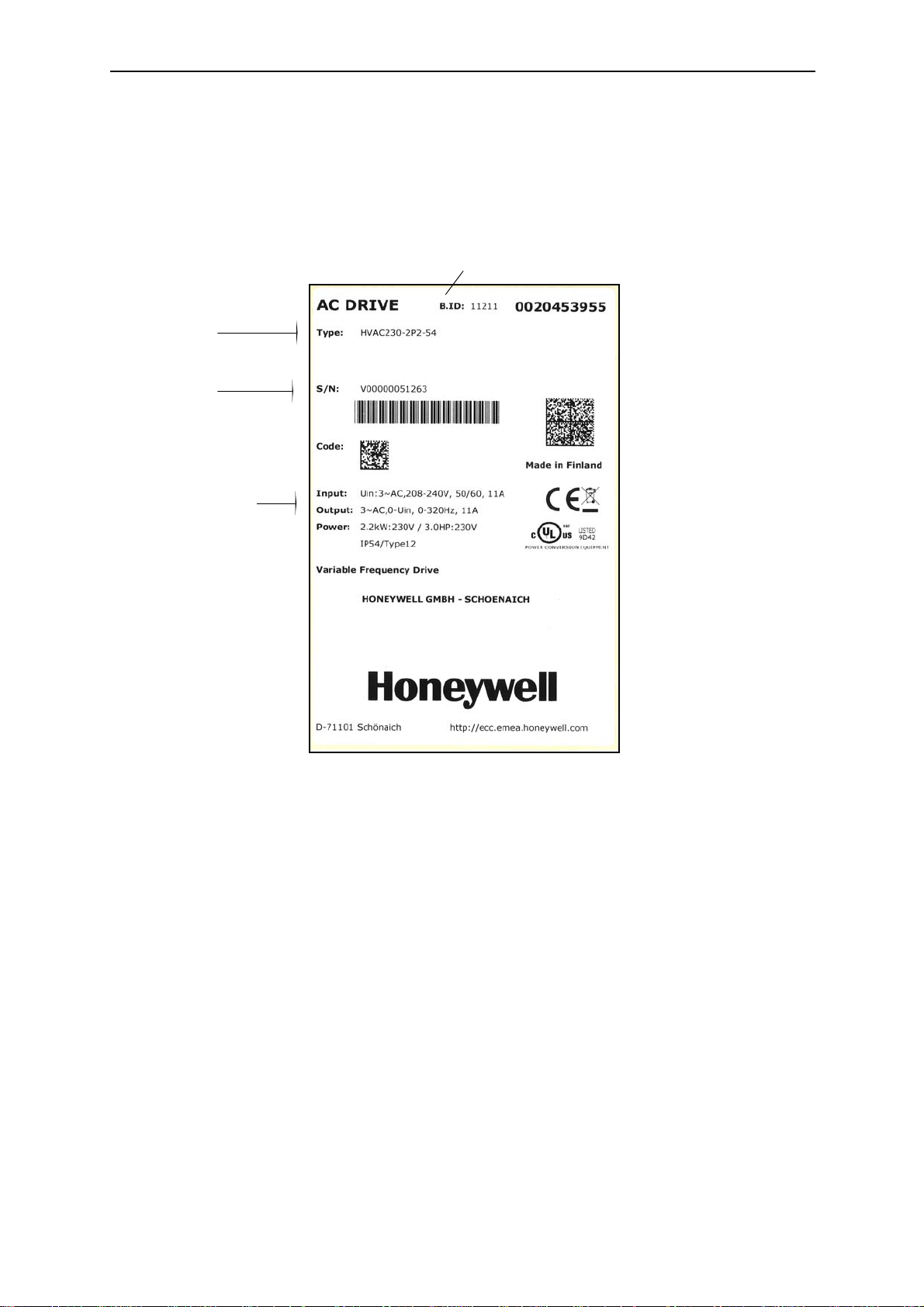
RECEIPT OF DELIVERY Honeywell • 6
Date code (batch ID):yyww
Product type:
Product serial
number
Electrical data and
enclosure class
2. RECEIPT OF DELIVERY
Check the correctness of delivery by comparing your order data to the drive in formation found
on the package label. If the delivery does not correspond to your order, contact the supplier
immediately. See chapter 2.3.
2
Honeywell • 7 RECEIPT OF DELIVERY
HVAC 400 -1P1 -54
Product range:
HVAC = SmartDrive HVAC
Supply voltage:
230 = 230 Vac 3~ (208-240 Vac)
400 = 400 Vac 3~ (380-480 Vac)
Nominal power:
1P1 = 1.1 kW
15P = 15 kW
110 = 110 kW
Enclosure classification:
21 = IP21
54 = IP54
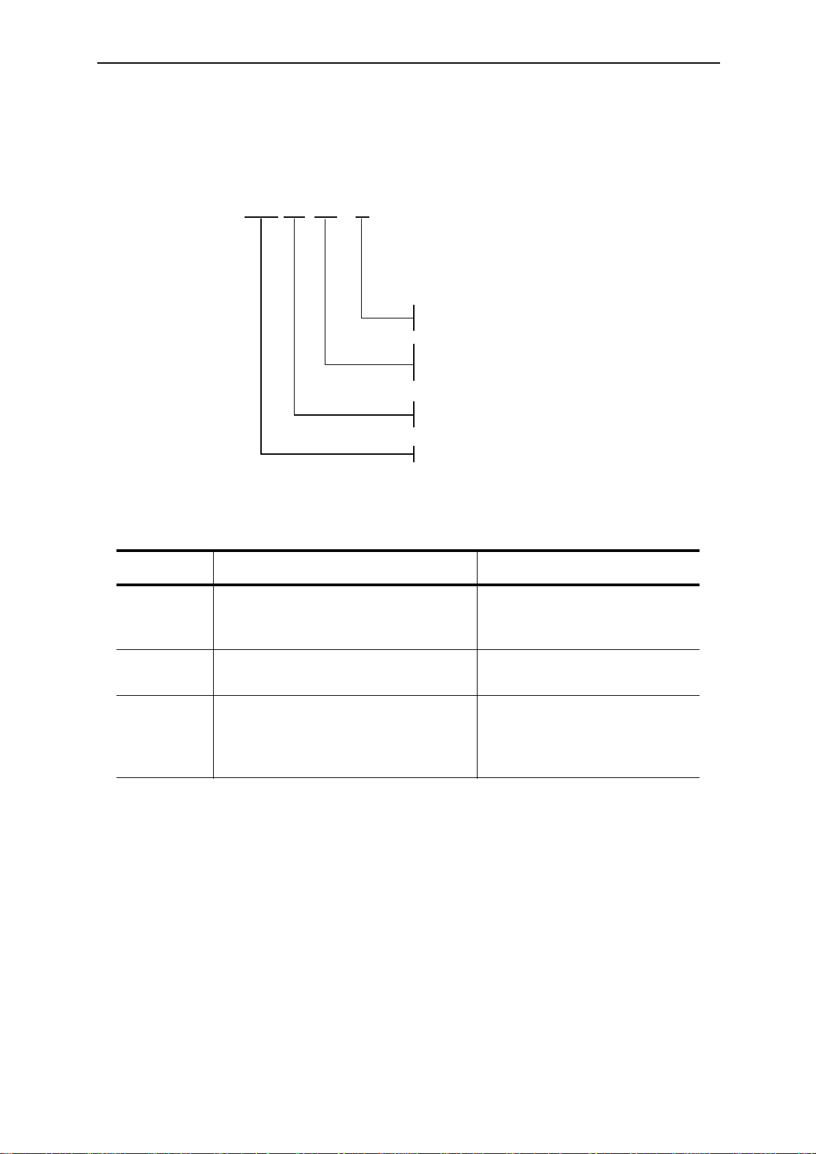
2.1 Type designation code
Honeywell type designation code is formed of a four-segment code. Each segment of the type
designation code uniquely corresponds to the product and options you have ordered. The code
is of the following format:
Special versions
ID Description Note
A
S Models with integrated load switch
T
Figure 1. Type designation code
Table 3. Special versions
Product delivered with advanced
commissioning keypad instead of
standard text keypad
Configured ready for the requirements of IT-network and including
the advanced commissioning keypad
instead of standard text keypad
Available only with 400V products (HVAC400-xxx-xxA)
Available only with IP54 400V
products (HVAC400-xxx-54S)
Available only with 230V products (HVAC230-xxx-xxT)
RECEIPT OF DELIVERY Honeywell • 8
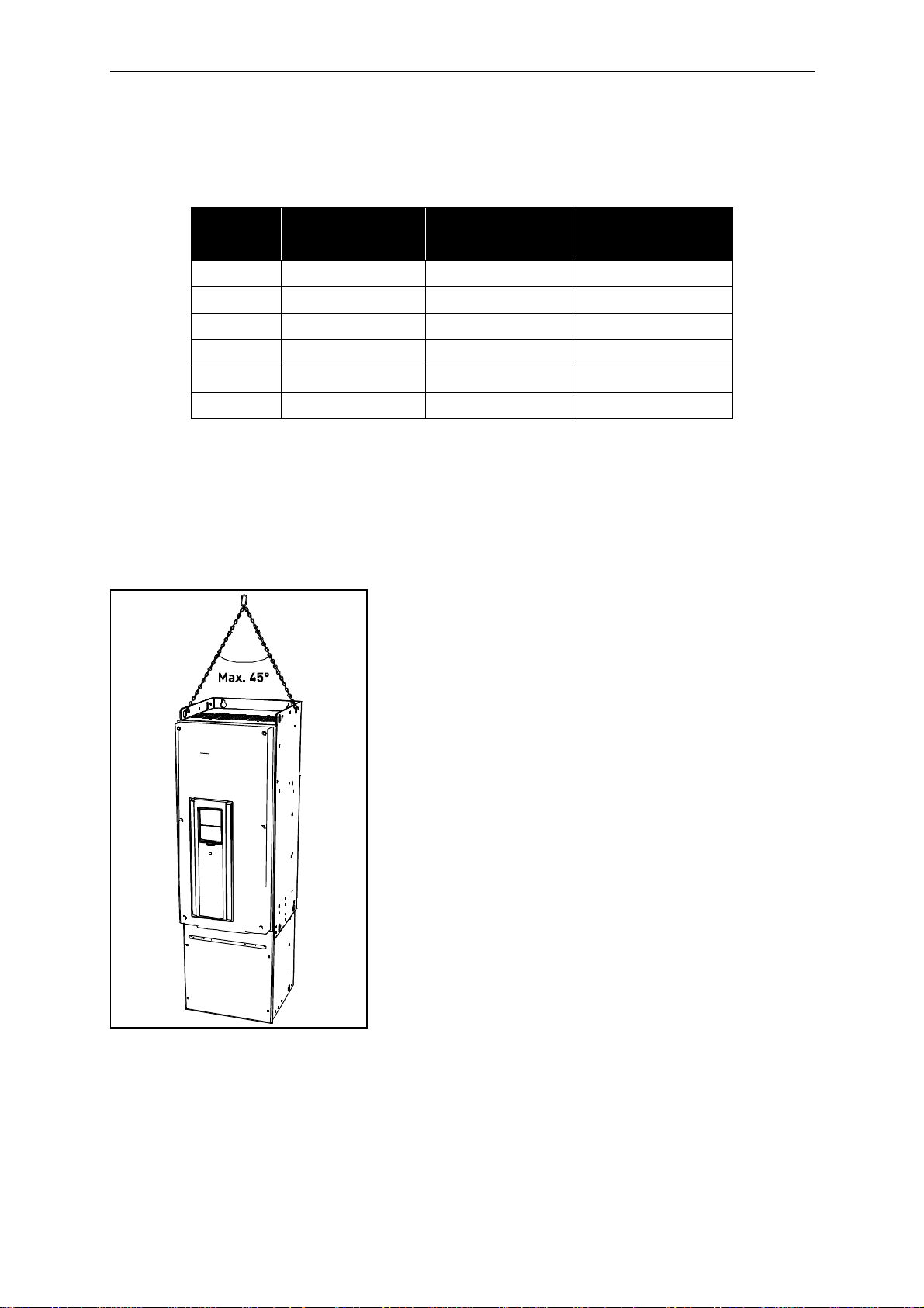
NOTE: First detach the drive from the pallet it has been
bolted to.
NOTE: Place the lifting hooks symmetrically in at least two
holes.The lifting device must be able to carry weight of the
drive.
NOTE: The maximum allowed lifting angle is 45 degrees.
2.2 Unpacking and lifting the drive
The weights of the drives vary greatly according to the size. You may need to use a piece of
special lifting equipment to move the converter from its package. Note the weights of each individual frame size in Table 4 below.
Frame
MR4 1.1 - 5.5 kW 0.55 - 3.0 kW 6.0
MR5 7.5 - 15.0 kW 4.0 - 7.5 kW 10.0
MR6 18.5 - 30.0 kW 11.0 - 15.0 kW 20.0
MR7 37.0 - 55.0 kW 18.5 - 30.0 kW 37.5
MR8 75.0 - 110 kW 37.0 - 55.0 kW 70.0
MR9 132 - 160 kW 75.0 - 90.0 kW 108.0
If you decide to use a piece of lifting equipment see picture below for recommendations to lift
the drive.
2.2.1 Lifting frames MR8 and MR9
Nominal power
400V 3~ series
Table 4. Frame weights
Nominal power
230V 3~ series
Weight [kg]
Figure 2. Lifting bigger frames
The drives have undergone scrupulous tests and quality checks at the factory before they are
delivered to the customer. However, after unpacking the product, check that no signs of transport damages are to be found on the product and that the delivery is complete.
2

Honeywell • 9 RECEIPT OF DELIVERY
Should the drive have been damaged during the shipping, please contact primarily the cargo
insurance company or the carrier.

RECEIPT OF DELIVERY Honeywell • 10
2.3 Accessories
After having opened the transport package and lifted the converter out, check immediately that
these various accessories were included in the delivery. The contents of the accessories bag
differ by drive size and IP protections class:
2.3.1 Size MR4
Item Quantity Purpose
Screws for power cable clamps
M4x16 screw 11
M4x8 screw 1 Screw for optional grounding
M5x12 screw 1 Screw for drive external grounding
Control cable grounding lamella 3 Control cable grounding
EMC cable clamps, size M25 3 Clamping power cables
Grounding clamp 2 Power cable grounding
‘Product modified’ label 1 Information about modifications
IP21: Cable grommet 3 Cable run-through sealing
IP54: Cable grommet 6 Cable run-through sealing
(6), control cable clamps (3),
grounding clamps (2)
Table 5. Contents of accessories bag, MR4
2.3.2 Size MR5
Item Quantity Purpose
Screws for power cable clamps
M4x16 screw 13
M4x8 screw 1 Screw for optional grounding
M5x12 screw 1 Screw for drive external grounding
Control cable grounding lamella 3 Control cable grounding
EMC cable clamps, size M25 1 Clamping brake resistor cable
EMC cable clamps, size M32 2 Clamping power cables
Grounding clamp 2 Power cable grounding
‘Product modified’ label 1 Information about modifications
IP21: Cable grommet, hole diameter 25.3
mm
IP54: Cable grommet, hole diameter 25.3
mm
Cable grommet, hole diameter 33.0 mm 2 Cable run-through sealing
1 Cable run-through sealing
4 Cable run-through sealing
(6), control cable clamps (3),
grounding clamps (4)
Table 6. Contents of accessories bag, MR5
2

Honeywell • 11 RECEIPT OF DELIVERY
2.3.3 Size MR6
Item Quantity Purpose
M4x20 screw 10
Screws for power cable clamps (6)
and grounding clamps (4)
M4x16 screw 3 Screws for control cable clamps
M4x8 screw 1 Screw for optional grounding
M5x12 screw 1 Screw for drive external grounding
Control cable grounding lamella 3 Control cable grounding
EMC cable clamps, size M32 1 Clamping brake resistor cable
EMC cable clamps, size M40 2 Clamping power cables
Grounding clamp 2 Power cable grounding
‘Product modified’ label 1 Information about modifications
Cable grommet, hole diameter 33.0 mm 1 Cable run-through sealing
Cable grommet, hole diameter 40.3 mm 2 Cable run-through sealing
IP54: Cable grommet, hole diameter 25.3 mm 3 Cable run-through sealing
Table 7. Contents of accessories bag, MR6
2.3.4 Size MR7
Item Quantity Purpose
M5x30 slotted nut 6 Nuts for power cable clamps
M4x16 screw 3 Screws for control cable clamps
M6x12 screw 1 Screw for drive external grounding
Control cable grounding lamella 3 Control cable grounding
EMC cable clamps, size M50 3 Clamping power cables
Grounding clamp 2 Power cable grounding
‘Product modified’ label 1 Information about modifications
Cable grommet, hole diameter 50.3 mm 3 Cable run-through sealing
IP54: Cable grommet, hole diameter 25.3 mm
Table 8. Contents of accessories bag, MR7
3 Cable run-through sealing

RECEIPT OF DELIVERY Honeywell • 12
2.3.5 Size MR8
Item Quantity Purpose
M4x16 screw 3 Screws for control cable clamps
Control cable grounding lamella 3 Control cable grounding
Cable lugs KP34 3 Clamping power cables
Cable insulator 11 Avoiding contact between cables
Cable grommet, hole diameter 25.3 mm 4 Control cable run-through sealing
IP00: Touch protection shield 1 Avoiding contact with live parts
IP00: M4x8 screw 2 Fixing the touch protection shield
Table 9. Contents of accessories bag, MR8
2.3.6 Size MR9
Item Quantity Purpose
M4x16 screw 3 Screws for control cable clamps
Control cable grounding lamella 3 Control cable grounding
Cable lugs KP40 5 Clamping power cables
Cable insulator 10 Avoiding contact between cables
Cable grommet, hole diameter 25.3 mm 4 Control cable run-through sealing
IP00: Touch protection shield 1 Avoiding contact with live parts
IP00: M4x8 screw 2 Fixing the touch protection shield
Table 10. Contents of accessories bag, MR9
2

Honeywell • 13 RECEIPT OF DELIVERY
Product modified
Date:
Date:
Date:
2.4 ‘Product modified’ sticker
In the small plastic bag included in the delivery you will find a silver Product modified sticker.
The purpose of the sticker is to notify the service personnel about the modifications made in
the drive. Attach the sticker on the side of the drive to avoid losing it. Should the drive be later
modified mark the change on the sticker.
Figure 3. ‘Product modified’ sticker
MOUNTING Honeywell • 14
128
100
Ø7
Ø13
100
190
IP21
Ø25
IP54
Ø25
3. MOUNTING
The drive must be mounted in vertical position on the wall or on the back plane of a cubicle.
Ensure that the mounting plane is relatively even.
The drive shall be fixed with four screws (or bolts, depending on the unit size).
3.1 Dimensions
Figure 4. SmartDrive dimensions, MR4
3

Honeywell • 15 MOUNTING
*Optional mounting holes (for NX replacement)
214
144
115
Ø7
Ø14
Ø7
100*
115
Ø7
100*
IP21
Ø33 Ø33Ø25
IP54
Ø25
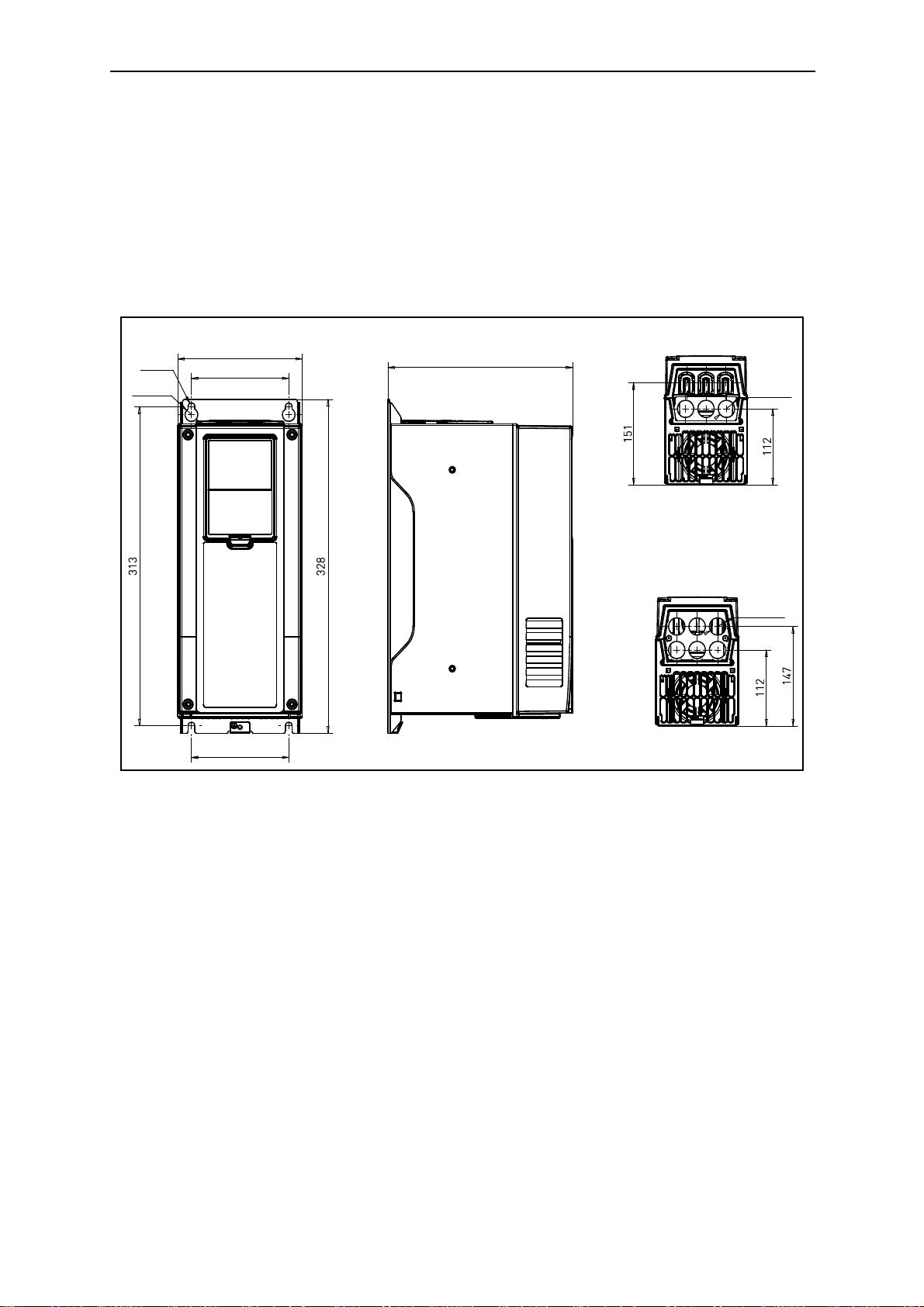
195
148
Ø 15,5
Ø9
Ø9
148
229
IP21
Ø40 Ø33 Ø40
IP54
Ø25Ø25
Figure 5. SmartDrive dimensions, MR5
Figure 6. SmartDrive dimensions, MR6
MOUNTING Honeywell • 16
259
Ø20
237
190
Ø9
Ø1 6
Ø51
IP21
IP54
Ø25
Ø50
Ø25
3 x 38
Ø60
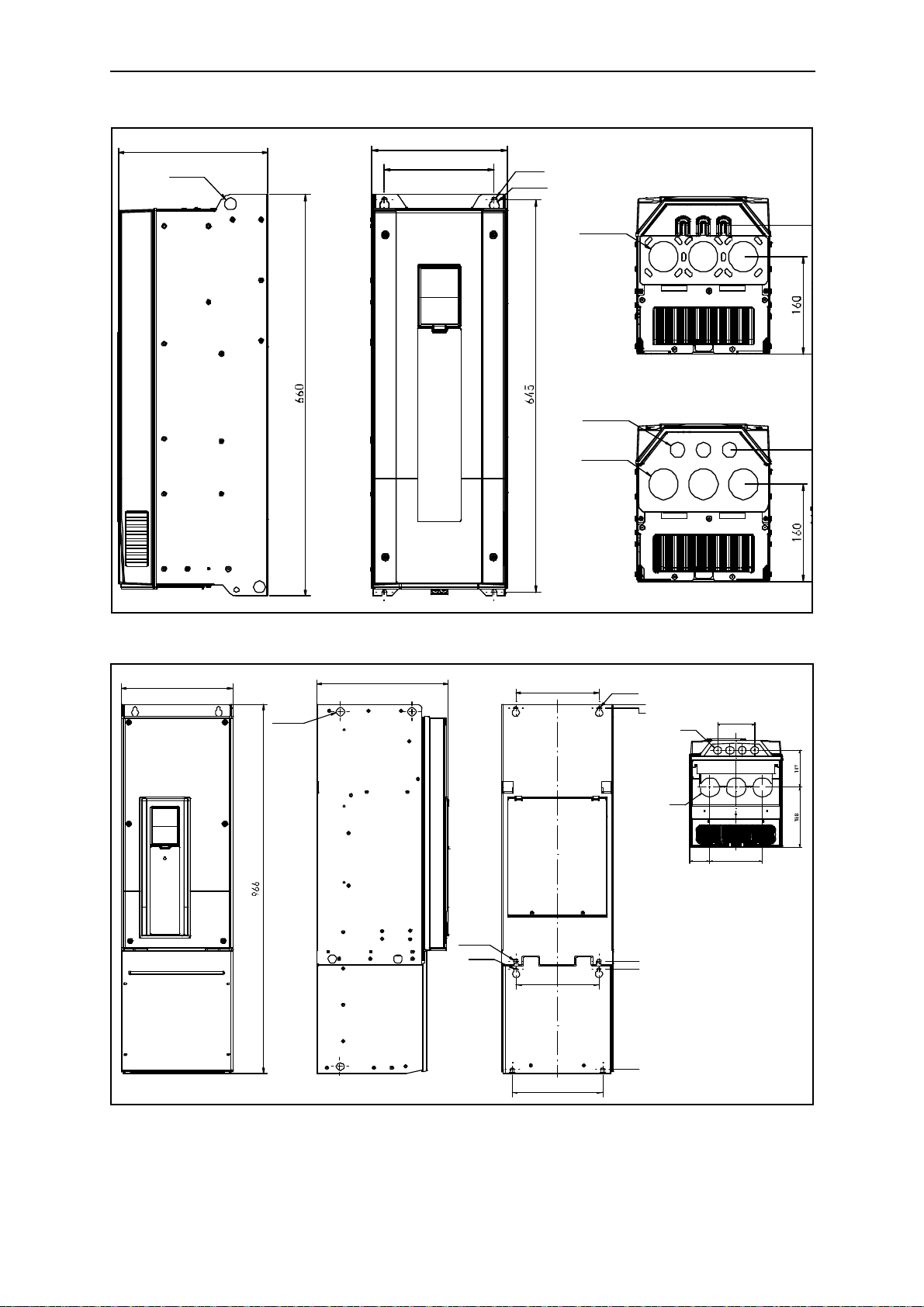
62,5 164
290
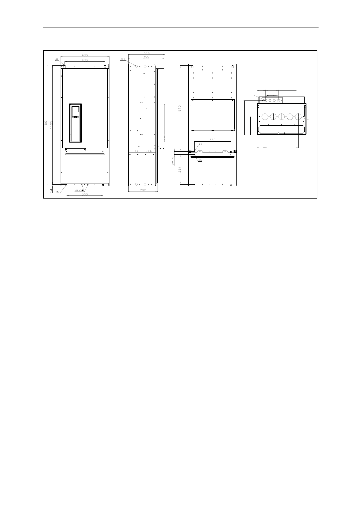
Ø22
343
Ø11
Ø9
216
672
694
956
235
217
Ø9
0
9
Figure 7. SmartDrive dimensions, MR7
Figure 8. SmartDrive dimensions, MR8 IP21 and IP54
3
Honeywell • 17 MOUNTING
84
3 x 42 = 126
Ø25
318
166
77
4 x 81,5 = 326
Ø59
Figure 9. SmartDrive dimensions, MR9 IP21 and IP54
MOUNTING Honeywell • 18
C
A
NK5_ 2
D
B
A
B
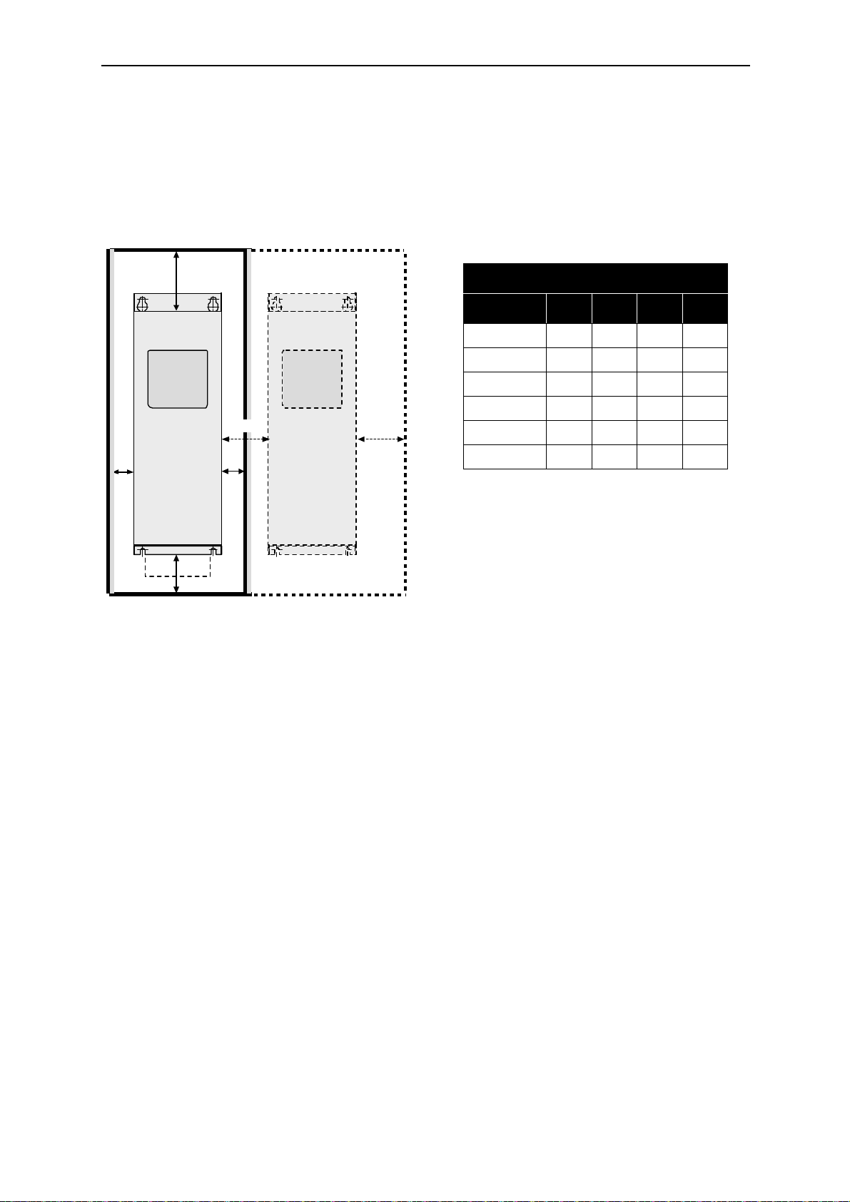
3.2 Cooling
The drives produce heat in operation and are cooled down by air circulated by a fan. Enough
free space shall therefore be left around the drive to ensure sufficient air circulation and cooling.
Different acts of maintenance also require certain amount of free space.
Make sure that the temperature of the cooling air does not exceed the maximum ambient temperature of the converter.
Min clearance [mm]
Type A
*
MR4 20 20 100 50
MR5 20 20 120 60
MR6 20 20 160 80
MR7 20 20 250 100
MR8 20 20 300 150
MR9 20 20 350 200
*
B
C D
Table 11. Min. clearances around drive
Figure 10. Installation space
A = clearance around the freq. converter (see also B)
B = distance from one drive to another or distance to cabinet wall
C = free space above the drive
D = free space underneath the drive
*. Min clearances A and B for
drives with IP54 enclosure is 0
mm.
3
Honeywell • 19 MOUNTING
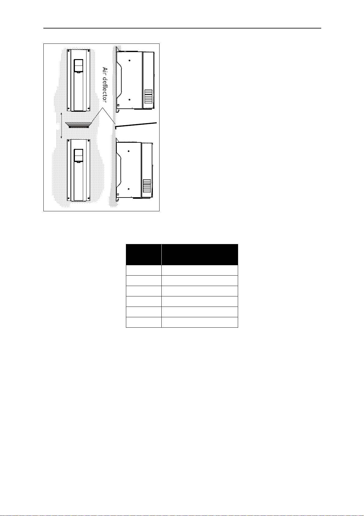
C+D
FRONT SIDE
Note that if several units are mounted above each
other the required free space equals C + D (see Figure 11.). Moreover, the outlet air used for cooling by
the lower unit must be directed away from the air intake of the upper unit by means of e.g. a piece of metal plate fixed to cabinet wall between the drives as
shown in Figure 11.
Figure 11. Installation space when drives are
mounted on top of each other
Type
Cooling air required
MR4 45
MR5 75
MR6 190
MR7 185
MR8 335
MR9 621
Table 12. Required cooling air
[m
3
/h]
POWER CABLING Honeywell • 20
Keypad
Control
U/T1
V/T2
W/T3
M
L1
L2
L3
Powe r unit
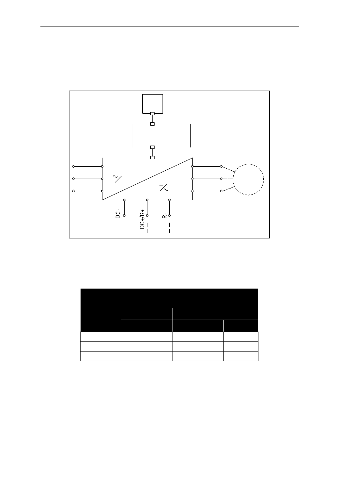
4. POWER CABLING
The mains cables are connected to terminals L1, L2 and L3 and the motor cables to terminals
marked with U, V and W. See principal connection diagram in Figure 12. See also Table 13 for
the cable recommmendations for different EMC levels.
Figure 12. Principal connection diagram
Use cables with heat resistance of at least +70°C. The cables and the fuses must be dimensioned according to the drive nominal OUTPUT current which you can find on the rating plate.
EMC levels
According to EN61800-3 (2004)
Cable type
Mains cable 1 1 1
Motor cable 3* 2 2
Control cable 4 4 4
Table 13. Cable types required to meet standards
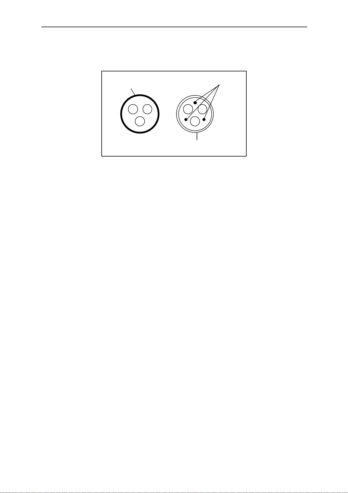
1 = Power cable intended for fixed installation and the specific mains voltage. Shielded
cable not required. (MCMK or similar recommended).
2 = Symmetrical power cable equipped with concentric protection wire and intended for the
specific mains voltage. (MCMK or similar recommended). See Figure 13.
3 = Symmetrical power cable equipped with compact low-impedance shield and intended
for the specific mains voltage. [MCCMK, EMCMK or similar recommended; Recommended cable transfer impedance (1...30MHz) max. 100mohm/m]. See Figure 13.
1st environment 2nd environment
Category C2 Category C3 Level C4
4
Honeywell • 21 POWER CABLING
PE conductor
and shield
PE conductors
Shield
*360º earthing of the shield with cable glands in motor end needed for EMC level C2.
4 = Screened cable equipped with compact low-impedance shield (JAMAK, SAB/ÖZCuY-
O or similar).
Figure 13.
NOTE: The EMC requirements are fulfilled at factory defaults of switching frequencies (all
frames).
NOTE: If safety switch is connected the EMC protection shall be continuous over the whole cable installation.
4.1 UL standards on cabling
To meet the UL (Underwriters Laboratories) regulations, use a UL-approved copper cable with
a minimum heat-resistance of +60/75°C. Use Class 1 wire only.
The units are suitable for use on a circuit capable of delivering not more than 100,000 rms symmetrical amperes, 600V maximum.
4.1.1 Cable dimensioning and selection
Table 14 shows the minimum dimensions of the Cu/Al-cables and the corresponding fuse sizes. Recommended fuse types are gG/gL.
These instructions apply only to cases with one motor and one cable connection from the drive
to the motor. In any other case, ask the factory for more information.

POWER CABLING Honeywell • 22
4.1.1.1 Cable and fuse sizes, frames MR4 to MR6
The recommended fuse types are gG/gL (IEC 60269-1) or class T (UL & CSA). The fuse voltage rating should be selected according to the supply network. The final selection should be
made according to local regulations, cable installation conditions and cable specification. Bigger fuses than what is recommended below shall not be used.
Check that the fuse operating time is less than 0.4 seconds. Operating time depends on used
fuse type and impedance of the supply circuit. Consult the factory about faster fuses. Honeywell offers recommendations also for high speed J (UL & CSA ), aR (UL recognized, IEC
60269-4) and gS (IEC 60269-4) fuse ranges.
Terminal cable size
Frame Type
I
L
[A]
Fuse
(gG/gL)
[A]
Mains and
motor cable
2
Cu [mm
]
Main
terminal
2
]
[mm
Earth
terminal
2
]
[mm
MR4
MR5
MR6
230 P55—230 P75
400 1P1—400 1P5
230 1P1—230 1P5
400 2P2—400 3P0
230 2P2—230 3P0
400 4P0—400 5P5
230 4P0
400 7P5
230 5P5
400 11P
230 7P5
400 15P
3.7—4.8
3.4—4.8
6.6—8.0
5.6—8.0
11—12.5
9.6—12.0
18.0
16.0
24.0
23.0
6 3*1.5+1.5
10 3*1.5+1.5
16 3*2.5+2.5
20 3*6+6 1—10 Cu 1—10
25 3*6+6 1—10 Cu 1—10
1—6 solid
1—4 stranded
1—6 solid
1—4 stranded
1—6 solid
1—4 stranded
1—6
1—6
1—6
31.0 32 3*10+10 1—10 Cu 1—10
400 18P 38.0 40 3*10+10 2.5—50 Cu/Al 2.5—35
230 11P
400 22P
230 15P
400 30P
48.0
46.0
62.0
61.0
Table 14. Cable and fuse sizes (MR4 to MR6)
50
63
3*16+16 (Cu)
3*25+16 (Al)
3*25+16 (Cu)
3*35+10 (Al)
2.5—50 Cu/Al 2.5—35
2.5—50 Cu/Al 2.5—35
The cable dimensioning is based on the criteria of the International Standard IEC60364-5-52:Cables
must be PVC-isolated; Max ambient temperature +30°C, max temperature of cable surface +70°C; Use
only cables with concentric copper shield; Max number of parallel cables is 9.
When using cables in parallel,
area and the max number of cables must be observed.
For important information on the requirements of the earthing conductor, see chapter Earthing and earth
fault protection of the standard.
For the correction factors for each temperature, see International Standard IEC60364-5-52.
NOTE HOWEVER that the requirements of both the cross-sectional
4
 Loading...