

Honeywell SiXC2W Installation Manual
SiXC2W Convert to Wireless / Convert to Wireless
Quick Installation Guide
Guide d'installation rapide
The Honeywell SiXC2W is an eight zone hardwire t o wireless converter used with
controllers that support Honeywell’s SiX™ series devices. It is useful in retrofit 12volt security syste m applications where existing contact wiring was used. It uses
those existing wired contacts and convert s them to wireless.
FEATURES
• Provides 12-volts for devices such as motion detectors, glass breaks, etc.
NOTE: Only two devices may be powered using the auxiliary output on the
SiXC2W.
• Provides 24-hour battery backup (4-hour if external devices are connected).
NOTE: It immediately sends a power lo ss signal to the controller in the event
the power is lost.
• When no battery is connected, low battery message wil l send to control
panel.
When battery is connected, and if battery voltage drops below 3.6VDC, a low
battery message sends to the control panel.
When only the battery is connected, and if t he battery voltage 3.4 V, system
will shut down.
• Support one button calibration
• Automatic zone configuration
• Easy setup in three steps
• Cover tamper protection
IMPORTANT!
Not to be used for fire, heat, or carbon monoxide detectors.
The Honeywell SiXC2W is an eight zone hardwire t o wireless converter used with
controllers that support Honeywell’s SiX™ series devices. It is useful in retrofit 12-volt
security system applicat ions where existing contact wiring was used. It uses t hose
existing wired contacts and converts them to wireless
CARACTÉRISTIQUES
• Provides 12-volts for devices such as motion detectors, glass breaks, etc.
NOTE: Only two devices may be powered using the auxiliary output on the SiXC2W.
• Provides 24-hour battery backup. (4-hour if external devices are connected). NOTE:
It immediately sends a power loss signal to the controller in the event the power is
lost.
• When no battery is connected, low battery message will send to control pane l.
When battery is connected, and if battery voltage drops below 3.6VDC, a low battery
message sends to the control panel.
When only the battery is connected, and if the battery voltage 3.4 V, system will shut
down.
• Support one button calibration
• Automatic zone configuration
• Easy setup in three steps
• Cover tamper protection
IMPORTANT!
Not to be used for fire, heat, or carbon monoxide detectors.
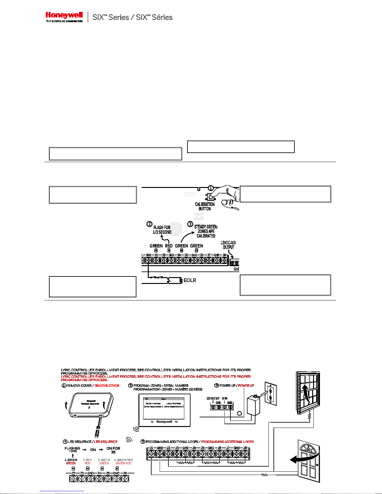
CALIBRATING CALIBRATING
The calibration process enables the SiXC2W to learn
what zones are to be active and what value EO L resistors
are used.
IMPORTANT!
Unused zones that are open ARE NOT
recognized and reported.
1. Ensure all zones are connecte d and not faulted.
2. On the SiXC2W, press and release the to p middle
button.
3. Indicator LED #2 will flash Red for 1 /2 second; then
LED #3 turns steady Green.
4. Calibration is in process
5. DONE. The SiXC2W is calibrated and ready to enro ll
in the control panel.
NOTES:
• If the SiXC2W loses both AC and battery backup
power, the zone calibration data is ret ained.
• If there is an existing resis tor, it MUST have a value
between 1K and 10K.The unit comes with eight (8)
2.2K resistors for zones that don’t have one.
IMPORTANT!
Once the SiXC2W is calibrate, any change in
the zone resistance the module must be
re-calibrated.
The calibration process enables the SiXC2W to learn
what zones are to be active and what value EO L
resistors are used.
IMPORTANT!
Unused zones that are open ARE NOT
recognized and reported
1. Ensure all zones are connecte d and not faulted.
2. On the SiXC2W, press and release the t op middle
button.
3. Indicator LED #2 will flash Red for 1 /2 second;
then LED #3 turns steady Green.
4. Calibration is in process
5. DONE. The SiXC2W is calibrated and ready to
enroll in the control panel .
NOTES:
• If the SiXC2W loses both AC and battery backup
power, the zone calibration data is ret ained.
• If there is an existing re sistor, it MUST have a value
between 1K and 10K.The unit comes with eight (8)
2.2K resistors for zones that don’t have one.
IMPORTANT!
Once the SiXC2W is calibrate, any change in the
zone resistance the module must be
re-calibrated.
ENROLLING / ENROLLING
Lyric Control
Lyric Controller Enrollment Process, See Controller’s installation instructions for its
proper programming process.
For Lyric Gateway
Use AlarmNet 360™ to enroll and program this sensor.
For Other Controls
For other controls that support SiX series device s, see the controller’s installation app for
details
NOTE: Once enrolled in a system, the SiXC2W cannot be used with another co ntroller
until it is removed from the current controller. See the Controller’s instructions
for details.
Lyric Control
Lyric Controller Enrollment Process, See Controller’s installation instructions for it’s
proper programming process.
For Lyric Gateway
Use AlarmNet 360™ to enroll and program this sensor.
For Other Controls
For other controls that support SiX series device s, see the controller’s installation app for
details
NOTE: Once enrolled in a system, the SiXC2W cannot be used with another co ntroller
until it is removed from the current controller. See the Controller’s instructions
for details.
2018 Honeywell International Inc. Honeywell and is a registered
trademark of Honeywell International Inc.
All other trademar ks are the properties of their respective owners. All
rights reserved.
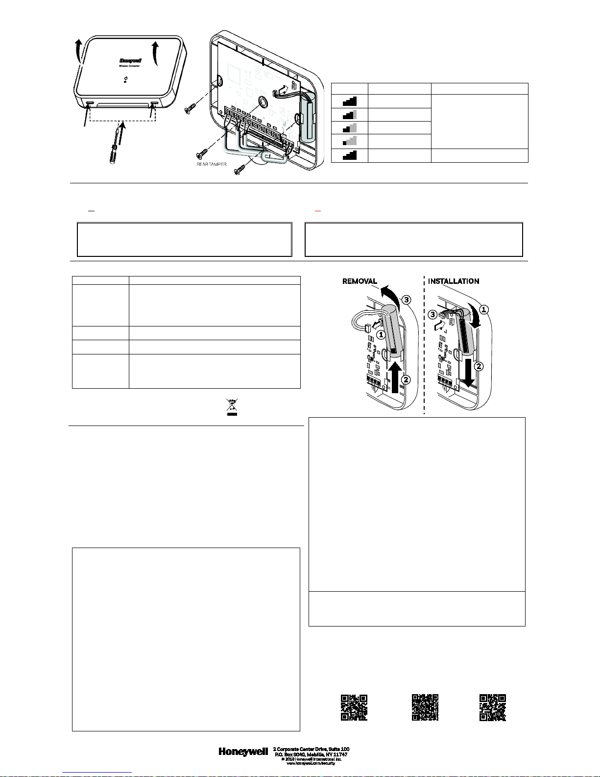
MOUNTING / MONTAGE
Signal strength:
• Rang of 1-4 bars (green), should be a minimum 1 green bar for
the zone being programmed.
• Four Red Bards indicate poor signal strength; the device should
be relocated.
• See the controller’s instruction for bar indication signal
strength values.
Icon Description Signal Strength
4 Green Bars
Good
3 Green Bars
2 Green Bars
1 Green Bar
4 Red Bars Relocate
TAMPER/LOW BATTERY REPORTING TAMPER/LOW BATTERY REPORTING
The SiXC2W reports this condition to the control. If a low battery or tamper condition
exists all zones used on the module shows a trouble on the control.
IMPORTANT:
The first battery test occurs 1 hour after power up. To quickly verify a good
backup battery, unplug and then plug back in the power supply; the system
will perform a battery test within 1 minute.
The SiXC2W reports this condition to the control. If a low battery or tamper condition
exists all zones used on the module shows a trouble on the control.
IMPORTANT:
The first battery test occurs 1 hour after power up. To quickly verify a good
backup battery, unplug and t hen plug back in the power supply; the system will
perform a battery test within 1 minute.
LED INDICATIONS
LED # / LED #
Functions / Functions
1 (Green / Green) Blinks once upon RF signal transmission ( HW zone
trigger/tamper and/or a fault me ssage), slow blink for a cover
tamper, quick blinks for enrollment or deletion / Blinks once
upon RF signal transmission (HW zone t rigger/tamper and/or a
fault message), slow blink for a cover tamper, quick blinks for
enrollment or deletion
2 (Red / Red)
Blinks 1s / 1s off when module needs cal ibrating / Blinks 1s /
1s off when module needs calibrating
3 (Green / Green)
Steady on when the module has been calibrate d. / Steady on
when the module has been calibrated.
4 (Green and Red /
Green and Red)
Green: 5VDC Power from the plug-in transformer is present
Red (blinking 1sec on / 1 sec off): Running on battery, DC
power not present. / Green: 5VDC Power from the plug-in
transformer is present Red (blinking 1sec on / 1 sec off):
Running on battery, DC power not present .
Approval Listings / Approbation s Homologations:
FCC / IC - ETL Listed to UL268 & 521
cETL Listed to ULC S530 & S531
Other Standards / Autres normes : RoHS
BATTERY REMOVAL AND INSTALLATION
Caution:
The batteries used in this device may present a fir e or chemical burn
hazard if mistreated. Do not rechar ge, disassemble, heat above 212°F
(100°C) or dispose of in fire. Use Panasonic CR123A or DURACELL DL123,
DL 123A Lithium batteries. Use of other batteries may present a risk of fire or
explosion. Keep used batteries away from children. Dispose of used batteries
properly.
Remove old batteries. Wait 10 s econds and then replace with four new
batteries. To avoid a low battery indication when installing new batteries, both
batteries must be installed within 15 se conds of installing the first one. Any
low battery condition that may have occu rred should clear when the back
plate is installed.
Mise en garde : Les piles utilis ées dans ce dispositif peuvent présenter des
risques d'incendie ou de br ûlure chimique si elles sont mal traitées. Ne
rechargez pas, ne désassemblez pas, ne faites pas chauffer et ne jet ez pas au
feu les piles à plus de 100 °C (212 °F). Utilisez des piles au lithium
Panasonic CR123A ou DURACELL DL123, DL 123A. L'utilisation d'autres
types de piles peut présenter des risques de feu ou d'explosion. Gardez les
vieilles piles hors de la portée des enfants. Débarrassez-vous des batteries
utilisées de façon appropriée.
Retirez les vieilles piles. Attendez 10 secondes et remplacer-les par quatre
nouvelles piles. Pour éviter une indication de piles faibles lorsque vous
installez de nouvelles piles, les dos (2) piles doivent être installées en deçà de
15 secondes après l'installation de la première. Toute condition de pilles
faibles qui aurait pu se pro duire devrait être rétablie une fois la plaque arrière
installée.
REFER TO THE INSTALLATION INSTRUCTIONS FOR THE CONTROL WITH
WHICH THIS DEVICE IS USED, FOR DETAILS REGARDING LIMITATIONS OF
THE ENTIRE ALARM SYSTEM.
POUR LES LIMITES DU SYSTÈME D’ALARME AU COMPLET, REPORTEZ-
VOUS AU GUIDE D’INSTALLATION DU PANNEAU DE COMMANDE
See Honeywell Installation Guide P/N
800-24139–
https://mywebtech.honeywell.com/.
Voir les instructions d'installation
complètes 800-24139-
https://mywebtech.honeywell.co m/.
Support / Pour de l’assistance e n ligne, visitez :
https://mywebtech.honeywell.com/
U.S. warranty / U.S. garantie: www.ho neywell.com/security/hsc/resources /wa
For patent info, see: / Pour des informations sur les brevets, voir :
www.honeywell.com/pate nts
MyWebTech
Warranty / Garantie
Patents / brevets
FEDERAL COMMUNICATIONS COMMISSION & INDUSTRY CANADA
STATEMENTS
The user shall not make any changes or modifications to the equipment unless
authorized by the Installation Inst ructions or User's Manual. Unauthorized changes
or modifications could void the user's authority to operate the equipment.
FCC / IC STATEMENT This device complies with Part 15 of the FCC Rules, and
Industry Canada’s license-exempt RSSs. Operation is subject to the following two
conditions: (1) This device may not cause harmf ul interference, and (2) This device
must accept any interference rece ived, including interference that may cause
undesired operation.
Cet appareil est conforme à la part ie 15 des règles de la FCC et exempt de licence
RSS d’Industrie Canada. Son fonctionnement es t soumis aux conditions suivantes:
(1) Cet appareil ne doit pas causer d’inter férences nuisibles. (2) Cet appareil doit
accepter toute interférence reçue y compris les interférences causant une
réception indésirable.
SPECIFICATIONS / SPÉCIFICATIONS:
Voltage
Transformer Part # ................................... 300-10259
Input Voltage ............................................... 100 ~ 240VAC, 50 ~60 Hz
Operating Voltage ..................................... 5VDC
Maximum Transformer Distance ...... 9.8ft. (3m)
Voltage Output ........................................... 12VDC @ 100mA (Up to three sets of 20–24
gauge wiring)
Battery/ Pile ................................................. P/N 300-10342
Environmental
Operating Temp ......................................... 14
F (-10C) to 140F (60C)
NOTE: Charging the lithium battery stops
when temperature is below 32F
(0C)
Relative Humidity ...................................... 95%, Non-condensing / 95% max. sans
condensation
Physical
Dimensions .................................................. Length 7.0 in (178 mm) x
Width 4.5 in (114 mm) x
Depth 1.5 in (38mm)
Mounting Hardware ................................. Double stick tape and screws
Zone Resistance ......................................... 1K to 10K Ohm EOL Resistors
Zone Wiring .................................................. 1,000ft (Each Zone)
Radio Frequency
Transmission Range ................................ 300ft (91.5m)
 Loading...