

Page 1

SE 3708C
UNINTERRUPTABLE
POWER MODULE
TECHNICAL
MANUAL
5452 Betsy Ross Drive
Santa Clara, CA 95054-1184
(408) 727-5170
FAX (408) 727-6707
P/N 66108566001, Rev. B
Page 2

SE 3708C Uninterruptable Power Module
SE 3708C ii 66108566001-Rev. B
Page 3

SE3708C Uninterruptable Power Module Manual
Hardware Warranty
Limited Warranty
Westinghouse Security Electronics (WSE) warrants to the original user the Equipment manufactured by
WSE as described herein (the Equipment) to be free from defects in material and workmanship for a period
of one year from the date of purchase by such user or fifteen (15) months from the date of shipment from the
factory, whichever is sooner, provided:
I WSE has been notified within such period by return of any alleged defective equipment free and
clear of any liens and encumbrances to WSE or its authorized Dealer at the address specified,
transportation prepaid, and
II the Equipment has not been abused, misused, or improperly maintained and/or repaired during
such period; and
III such defect has not been caused by ordinary wear and tear; and
IV such defect is not a result of voltage surges/brownouts, lightning, water damage/flooding, fire,
explosion, earthquakes, tornadoes, acts of aggression/war, or similar phenomena; and
V accessories used as an integral to WSE Systems have been approved by WSE (e.g., coax,
batteries, etc.); and
VI the Equipment has been installed, the installation supervised, or installation tested by an
unauthorized WSE Dealer.
WSEs Proximity Command Keys are warranted for 5 years. WSE shall at its option, either repair or
replace, free of charge, the Equipment found, upon WSEs inspection, to be so defective, or if agreed upon,
refund the purchase price, less a reasonable allowance for depreciation, in exchange for the Equipment.
Magnetic Stripe cards are warranted as described by the manufacturers warranty.
WSE MAKES NO OTHER WARRANTY, AND ALL IMPLIED WARRANTIES INCLUDING ANY WARRANTY
OF MERCHANT ABILITY OR FITNESS FOR A PARTICULAR PURPOSE ARE LIMITED TO THE
DURATION OF THE EXPRESSED WARRANTY PERIOD AS SET FORTH ABOVE.
WSES MAXIMUM LIABILITY HEREUNDER IS LIMITED TO THE PURCHASE PRICE OF THE
EQUIPMENT. IN NO EVENT SHALL WSE BE LIABLE FOR ANY CONSEQUENTIAL, INDIRECT,
INCIDENTAL, OR SPECIAL DAMAGES OF ANY NATURE ARISING FROM THE SALE OR USE OF THE
EQUIPMENT.
Some states do not allow limitations on incidental or consequential damages or how long an implied
warranty lasts, so the above limitations may not apply. This warranty gives specific legal rights, however,
other rights which vary from state to state, may pertain.
66108566001-Rev. B iii SE 3708C
Page 4

SE 3708C Uninterruptable Power Module
NOTICE
The SE 3708C Uninterruptable Power Module manufactured by Westinghouse Security Electronics has
been tested and found to comply with the limits for a Class B digital device, pursuant to Part 15 of the FCC
Rules. These limits are designed to provide reasonable protection against harmful interference in a
residential installation. This equipment generates, uses, and can radiate radio frequency energy and, if not
installed and used in accordance with the instructions herein, may cause harmful interference to radio
communications. However, there is no guarantee that interference will not occur in a particular installation.
If this equipment does cause harmful interference to radio or television reception, which can be determined
by turning the equipment off and on, the user is encouraged to try to correct the interference by one or more
of the following measures:
• Reorient or relocate the receiving antenna.
• Increase the separation between the equipment and receiver.
• Connect the equipment into an outlet on a circuit different from that to which the receiver is
connected.
• Consult the dealer or an experienced radio/TV technician for help.
SE 3708C iv 66108566001-Rev. B
Page 5

SE3708C Uninterruptable Power Module Manual
TABLE OF CONTENTS
SECTION 1 INTRODUCTION
1.1 PURPOSE .................................................................................................................................. 1-1
1.2 SCOPE ....................................................................................................................................... 1-1
1.3 CONFIGURATIONS ................................................................................................................... 1-2
1.4 GENERAL INFORMATION......................................................................................................... 1-2
1.4.1 System Overview ........................................................................................................ 1-2
1.4.2 System Applications.................................................................................................... 1-2
1.5 SAFETY INSTRUCTIONS.......................................................................................................... 1-3
SECTION 2 DESCRIPTION
2.1 PHYSICAL DESCRIPTION ........................................................................................................2-4
2.2 FUNCTIONAL DESCRIPTION ................................................................................................... 2-4
2.2.1 Low Voltage Switching Power Supply Circuitry............................................................ 2-5
2.2.2 Battery Disconnect Circuitry ........................................................................................ 2-5
2.2.3 Control and Indicators Circuitry ...................................................................................2-5
2.2.4 400 Hz Inverter ........................................................................................................... 2-6
2.2.5 Power On/Off Switch and Pilot Light ........................................................................... 2-6
SECTION 3 INSTALLATION
3.1 LOCATION and MOUNTING ...................................................................................................... 3-1
3.2 WIRING REQUIREMENTS ........................................................................................................ 3-1
3.2.1 ACU Cable Connections ............................................................................................. 3-2
3.2.2 Lock Power Wiring Connections .................................................................................3-3
3.2.3 Battery Cable Connections ......................................................................................... 3-5
SECTION 4 WIRING REQUIREMENTS
4.1 CUSTOMER SERVICE.................................................................................................. 4-1
4-2 TROUBLESHOOTING GUIDE ...................................................................................... 4-1
APPENDICES
APPENDIX A SPECIFICATION .......................................................................................................A-1
APPENDIX B SE 3708 VERSIONS ................................................................................................. B-1
66108566001-Rev. B v SE 3708C
Page 6

SE 3708C Uninterruptable Power Module
SE 3708C vi 66108566001-Rev. B
Page 7

SECTION 1
INTRODUCTION
This manual provides basic information on the installation and operation of the Westinghouse Security
Electronics (WSE) SE 3708C Uninterruptable Power Module. This information includes specifications, a brief description of the operation, controls and indicators, relevant installation data, and a
troubleshooting guide.
NOTE: Changes or modifications to the equipment
described herein which are not expressly
approved by Westinghouse Security Electronics
can void authority of the user to operate the system.
1.1 PURPOSE
The purpose of this manual is to provide the information required for installing, operating, and
troubleshooting the SE 3708C Uninterruptable Power Module.
1.2 SCOPE
The information provided in this manual is intended for personnel who will be installing the SE 3708C,
placing the unit in operation, and performing the troubleshooting procedures described herein.
Repairs to the SE 3708C shall be limited to those that can be performed without removing the unit from
its case with the exception of replacing fuses.
The information contained in this manual assumes that the reader is familiar with access control and
alarm monitoring technology and standard installation practices. Thus, the manual is not intended to
be a complete system installation guide or system service manual for dealers or end-users. As such,
the manual is a supplementary guide, providing only that information and data which is unique to the
SE 3708C.
The information provided in this manual is not intended to either conflict with or supplement the specific
building codes, electrical codes, or safety codes to which any given installation must conform.
This manual is organized as follows:
Section 1 . . . . . . . . INTRODUCTION
Section 2 . . . . . . . . DESCRIPTION
Section 3 . . . . . . . . INSTALLATION
Section 4 . . . . . . . . MAINTENANCE
Appendix A . . . . . . SPECIFICATIONS
Appendix B . . . . . . SE 3708 VERSIONS
66108566001-Rev. B 1-1 SE 3708C
Page 8

Introduction SE 3708C Power Supply Manual
1.3 CONFIGURATIONS
The SE 3708C Uninterruptable Power Module is identified by four different part numbers depending
upon the lock power output and the AC power input. These part numbers and the Power Module
configurations are shown in Table 1-1.
Table 1-1. SE 3708C Configurations
Part Number Lock Power Input Power
92370811112 +12 VDC 50/60 Hz, 120 VAC
92370812124 +24 VDC 50/60 Hz, 120 VAC
92370813212 +12 VDC 50/60 Hz, 230 VAC
92370814224 +24 VDC 50/60 Hz, 230 VAC
1.4 GENERAL INFORMATION
General information on the SE 3708C system operation and system applications is provided below.
1.4.1 SYSTEM OVERVIEW
The SE 3708C Uninterruptable Power Module is a true uninterruptable power supply in that it can take
power either from the power lines or from external storage batteries which are always on-line in case
the power fails. Normally, when AC power is available, the batteries are always kept charged; when
the power fails, the batteries take over immediately until AC power is restored.
To accomplish this, the 3708C is actually two power supplies working together. The first, or primary
power supply, provides low voltage for locks, for battery charging, and for the secondary power supply
which, in turn, produces all system voltages. During power outages, the batteries continue to provide
the low voltage needed for locks and the secondary power supply.
1.4.2 SYSTEM APPLICATIONS
The 3708C can provide enough power to run an access control system consisting of the following
components:
• Up to 2 Access control unit(s).
• Up to 16 Multiple Switch Monitor(s) (SE 774) or Door Switch Monitor(s) (SE770).
SE 3708C 1-2 66108566001-Rev. B
Page 9

Installation Introduction
• Up to 16 SE 2814/15 Sensors
• One or two batteries (12 VDC or 24 VDC).
• One or two SE 778 or 778A Annunciator/Control Module(s) powered by the ACU in 800-
series systems.
• One Modem (or similar accessory).
• Several low current locking devices or similar accessories (see below).
As shown in Table 1-1, the SE 3708C is available in four versions, 3708C-112, 3708C-124, 3708C212, and the 3708C-224. The 3708C-112 and 3708C-212 are intended for systems with 12-volt locks.
The 3708C-124 and 3708C-224 are to be used for systems with 24-volt locks. Since the batteries
provide lock voltage during power outages, the lock voltage requirement will also determine the battery
voltage requirement. Since the 12-volt 3708C-112/212 and the 24-volt 3708C-124/224 are set and
adjusted to their respective voltages at the factory, they cannot be converted in the field.
At facilities without emergency power systems, the SE 3708C can provide limited emergency power
to maintain access control. The total amount of power it can deliver, however, is fixed, and should not
be exceeded. Doing so may blow fuses, or damage the unit. Therefore, any devices in addition to
those listed above may cause the 3708C to be damaged or operate incorrectly.
As noted, installation personnel should be careful to avoid overloading the system. However, due to
the variety of locks and system configurations available, it is impossible to state exactly how many locks
the SE 3708C is capable of driving. However, for a typical system configuration consisting of one
Access Control Unit controlling several doors, the continuous lock power load should not exceed 4
amps at 12 VDC or 3 amps at 24 VDC. If additional lock power is required, or the system includes two
access control units, some or all lock power will probably need to come from an external power supply
instead of the SE 3708C. It is important to remember that any external power supply must function
independently and must not be paralleled with the SE 3708C.
Consequently, heavy lock power loads, monitoring modules such as motion detectors, glass break
detectors, infrared sensors, and smoke detectors should not be powered by the SE 3708C; they should
have separate power supplies.
1.5 SAFETY INSTRUCTIONS
SAVE THESE INSTRUCTIONS. THIS MANUAL CONTAINS IMPORTANT SAFETY INSTRUCTIONS.
CONSERVER CES INSTRUCTIONS. CETTE NOTICE CONTIENT DES INSTRUCTIONS
IMPORTANTES CONCERNANT LA SECURITE.
CAUTION: A BATTERY CAN PRESENT A RISK OF ELECTRICAL SHOCK OR BURN FROM HIGH
SHORT-CIRCUIT CURRENT. OBSERVE PROPER PRECAUTIONS.
66108566001-Rev. B 1-3 SE 3708C
Page 10

Introduction SE 3708C Power Supply Manual
ATTENTION: UNE BATTERIE PEUT PRESENTER UN RISQUE DE CHOC ELECTRIQUE OU DE
BRULURE PAR TRANSFERT DENERGIE. SUIVRE LES PRECAUTIONS QUI SIMPOSENT.
WHEN REPLACING BATTERIES USE THE SAME NUMBER AND THE FOLLOWING TYPE
BATTERIES (TABLE 1-2).
POUR LE REMPLACEMENT, UTILIZER LE MEME NOMBRE DE BATTERIES DU MODELE
SUIVANT (TABLE 1-2).
PROPER DISPOSAL OF BATTERIES IS REQUIRED. REFER TO YOUR LOCAL CODES FOR
DISPOSAL REQUIREMENTS.
LELIMINATION DES BATTERIES EST REGLEMENTEE. CONSULTER LES CODES LOCAUX A
CET EFFET.
Table 1-2. Recommended Standby Batteries
Manufacturer Description Part Number
Eagle-Picher 12 V, 31-amp-hour, sealed, lead-acid CFM12V33
Gates 12 V, 25-amp-hour, sealed, lead-acid 0820-0020
Yuasa 12 V, 35 amp-hour, sealed, lead-acid NP38-12
Elpower 12 V, 30 amp-hour, sealed, lead-acid EP 12330-24
Power Sonic 12 V, 22 amp-hour, sealed, lead-acid PS-12240
Power Sonic 12 V, 28 amp-hour, sealed, lead-acid PS-12280
Power Sonic 12 V, 40 amp-hour sealed, lead-acid PS-12400
SE 3708C 1-4 66108566001-Rev. B
Page 11

SECTION 2
DESCRIPTION
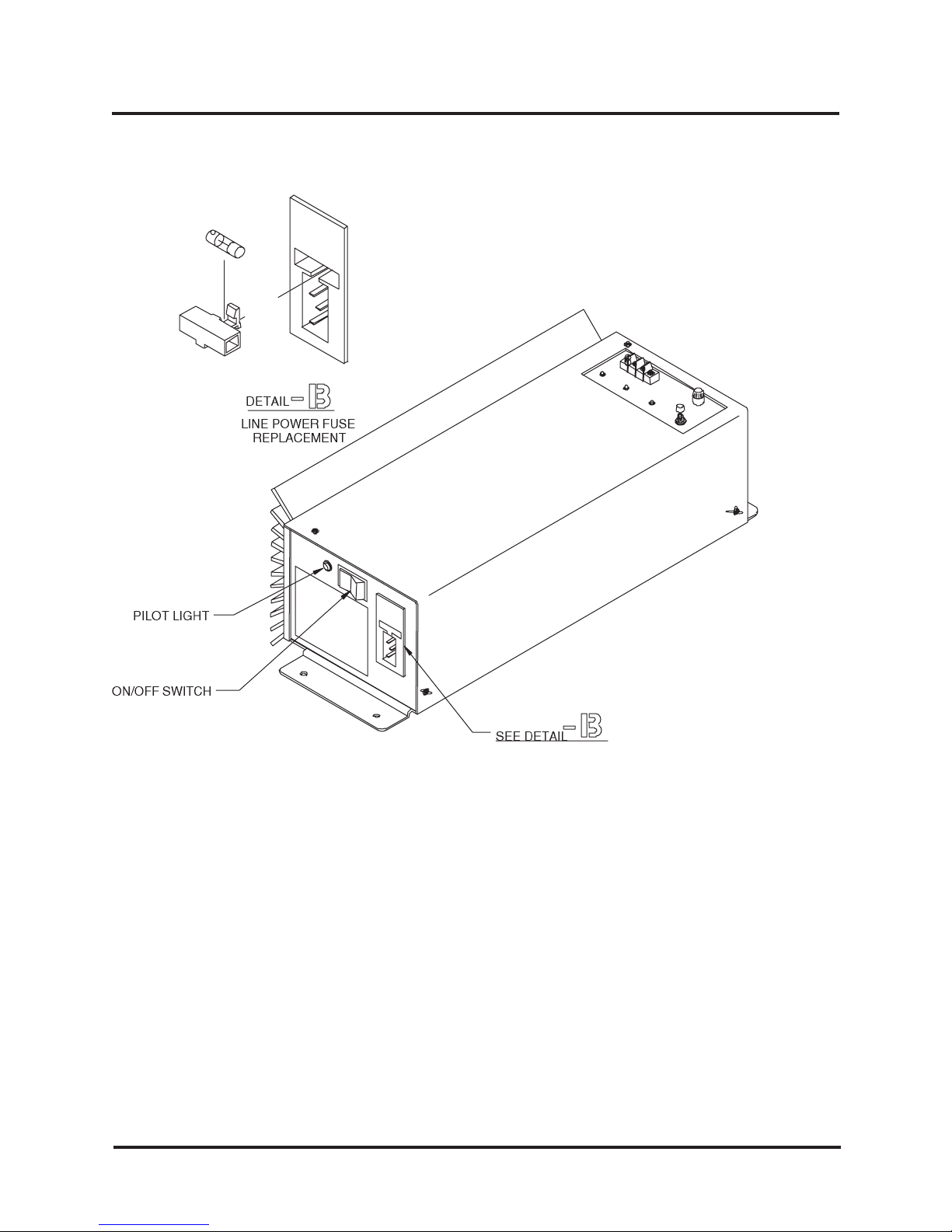
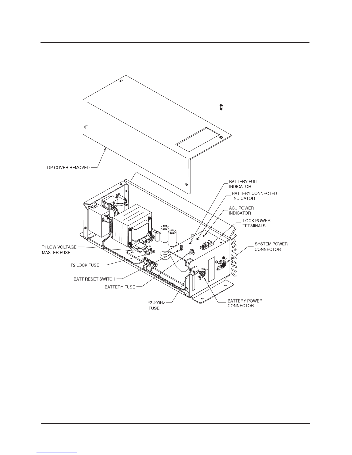
The SE 3708C Uninterruptable Power Supply (Figures 2-1 and 2-2) provides the requisite input AC
and DC power for WSE 700-series and 800-series ACUs.
66108566001-Rev. B 2-1 SE 3708C
Page 12
Description SE 3708C Power Supply Manual
Figure 2-1. SE 3708C Uninterruptable Power Module
SE 3708C 2-2 66108566001-Rev. B
Page 13
Description Introduction
Figure 2-2. SE 3708C Uninterruptable Power Module (Cover Removed)
66108566001-Rev. B 2-3 SE 3708C
Page 14
Description SE 3708C Power Supply Manual
y
g
y
y
(
)
)
)
y
y
y
2.1 PHYSICAL DESCRIPTION
The SE 3708C Uninterruptable Power Module measures 18 inches (45.7 cm) long by 7.2 inches (18.3
cm) wide by 5.2 inches (13.2 cm) high. The unit weighs 16 pounds (7.3 kg).
As shown in Figures 2-1 and 2-2, the SE 3708C consists of a chassis with mounting flanges at each
end, a two-sided perforated cover, a control panel, a heat sink, and two end covers.
The AC input connector, the Line Fuse, the Pilot Light, and the ON/OFF Switch are mounted on the
left end cover. The three status LEDs, the Battery Reset Switch, the Battery Fuse, and the Lock Power
terminal strip are mounted on the control panel. Output power connectors, consisting of the Battery
Power Connector and the System Power Connector are mounted on the right cover. The rear of the
unit consists of a deeply-finned heat sink. The two-sided perforated cover is easily removed by means
of four Phillips-head screws for access to the chassis-mounted components.
2.2 FUNCTIONAL DESCRIPTION
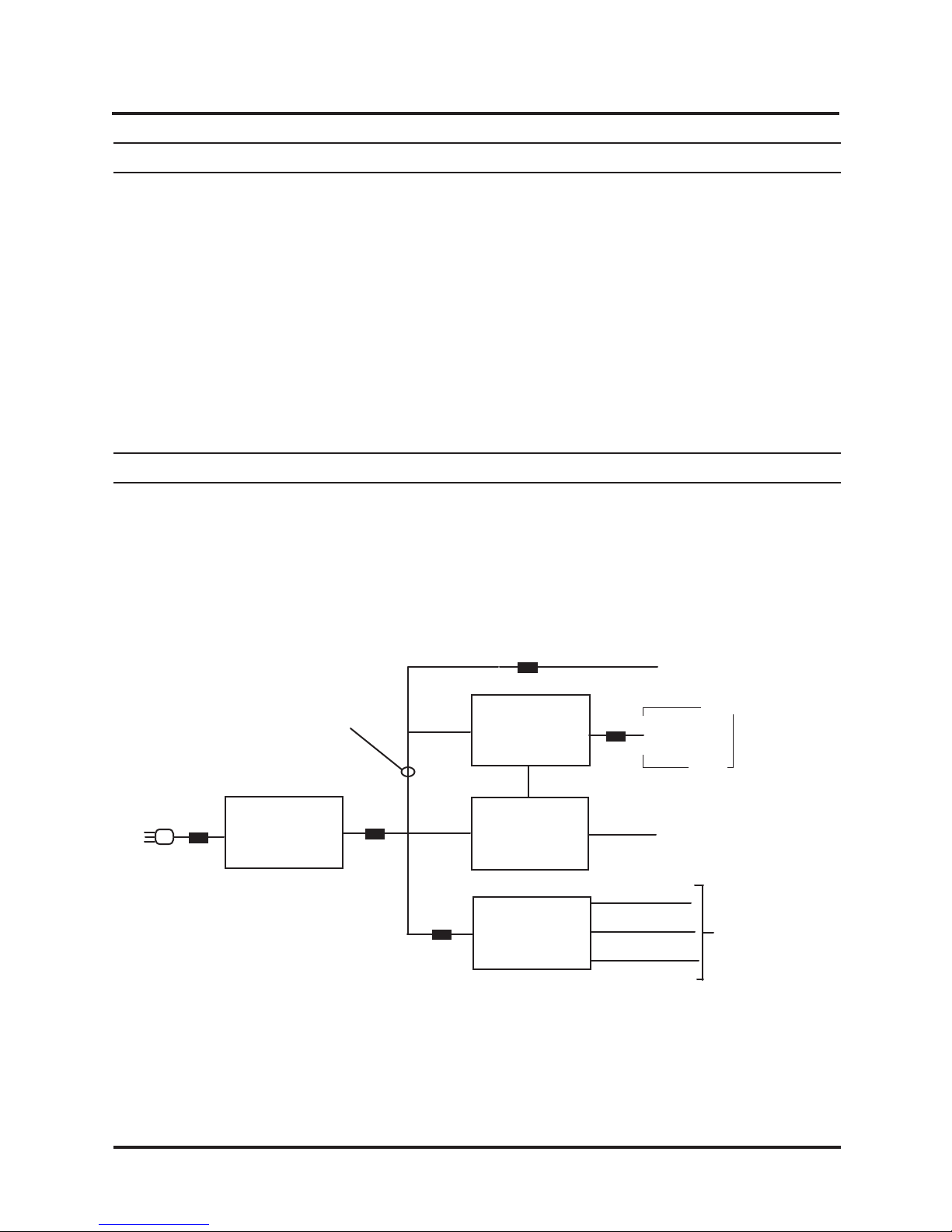
A functional block diagram of the SE 3708C Uninterruptable Power Module is shown in Figure 2-3. The
SE 3708C circuitry consists of four main functional elements as described below.
AC
Input
Line
Fuse
+12VDC/+24VDC
Low Voltage
Switchin
Power Suppl
Figure 2-3. SE 3798C Functional Block Diagram
Low Volt.
Master
Fuse
Inverter
Fuse
Lock Fuse
Batter
Disconnect
Circuitr
Control &
Indicators
Circuitr
400 Hz.
Inverter
Batter
Fuse
80 VAC
50 VAC (p-p
40 VAC (p-p
Lock Power
12VDC/ 24VDC
Backup
Batter
Power Fail
p-p
ACU Power
SE 3708C 2-4 66108566001-Rev. B
Page 15

Description Introduction
2.2.1 LOW VOLTAGE SWITCHING POWER SUPPLY CIRCUITRY
The purpose of the Low Voltage Switching Power Supply circuitry is to convert the input AC (120 VAC
or 230 VAC) to a 12/24 VDC level. This DC level will be +12 VDC on units that are configured to supply
power to 12 VDC locks and +24 VDC to units that are configured to supply power to 24 VDC locks.
The 12/24 VDC level is routed to the Lock Power terminals (via the Lock Fuse) and to the Control and
Indicators Circuitry as well as to the 400 Hz Inverter. The Lock Fuse is a 5-amp, normal-blow fuse on
12 VDC units and a 3-amp, normal-blow fuse on 24 VDC units.
As shown in Figure 2-3, the input AC is routed through the Line Power Fuse which is a 2-amp, slowblow fuse on 120 VAC units and a 1-amp, slow-blow fuse on 230 VAC units. The output of the Low
Voltage Switching Power Supply is routed through the Low Voltage Master Fuse before being routed
to the inputs of the Battery Disconnect, the Control Circuitry and Indicators circuitry, and the 400 Hz
Inverter circuitry. The Low Voltage Master Fuse is a 7-amp, normal-blow fuse on units powering +12
VDC locks and a 4-amp, slow-blow fuse on units powering +24 VDC locks.
2.2.2 BATTERY DISCONNECT CIRCUITRY
The Battery Disconnect Circuit consists primarily of the Battery Disconnect Relay and its associated
circuitry. During normal operation, when the SE 3708C is being powered from the AC line, the battery
(or batteries) are being kept at full charge by means of the DC power (+12 VDC or +24 VDC) from the
Low Voltage Switching Power Supply, via the Battery Disconnect Circuitry and the Battery Fuse.
This circuitry keeps the backup battery connected as long as AC power is available. Should a power
failure cause loss of AC power to the SE 3708C, or should the Low Voltage Power Supply fail, the
remainder of the Power Module circuitry will remain functioning normally since they will be powered
from the Backup Battery supply via the Battery Fuse and the Battery Disconnect Circuitry.
The Battery Fuse is a 10-amp, normal-blow fuse.
2.2.3 CONTROL AND INDICATORS CIRCUITRY
One function of the Control and Indicator Circuitry is to sense the voltage level of the 12/24 VDC level.
When this level drops below a certain level, it will cause the Battery Disconnect Relay to open,
disconnecting the SE 3708C from the ACU, and thus protecting the battery from over-discharging.
Another function of this circuitry is to send a POWER FAIL message to the ACU in the event that the
SE 3708C is operating on DC power and the battery charge has reached approximately the halfdischarged state. This signal will be generated before the battery reaches a state of discharge where
the Battery Disconnect Relay will disconnect the unit from the ACU.
Indicator LEDs
As shown in Figure 2-2, three LEDs are mounted on the SE 3708C control panel. These LEDs are
controlled by the Control and Indicator Circuitry and function as follows:
66108566001-Rev. B 2-5 SE 3708C
Page 16

Description SE 3708C Power Supply Manual
BATT FULL VOLTS Lights to indicate a fully-charged battery. This LED will go out approxi-
mately 5 minutes after AC power is lost and the SE 3708C switches over
to fully-charged backup batteries. The POWER FAIL message will be
sent to the ACU at the same time that the LED goes out.
BATT CONN Lights to indicate that Battery Disconnect Relay is energized, thus
connecting the backup battery to the system.
ACU PWR Lights to indicate that the 400 Hz Inverter is supplying power to the ACU.
Battery Reset Switch
There is a momentary contact pushbutton switch on the control panel labeled BATT RESET. This
switch is only used in the event that the ACU is being powered from the SE 3708C backup batteries
and the batteries have been disconnected to be replaced with fresh batteries. After the fresh batteries
have been connected to the SE 3708C, the BATT RESET switch must be pressed in order to pull in
the Battery Disconnect Relay and apply DC power to the unit.
2.2.4 400 HZ INVERTER
As shown in Figure 2-3, the 400 Hz Inverter inputs the 12/24 VDC level from the Low Level Switching
Power Supply via the Inverter Fuse. The output of this circuitry supplies the ACU with its primary AC
power. Three power levels are supplied: an 80 VAC, a 50 VAC, and a 40 VAC level.
Note that these power levels are measured peak-to peak. The 80 VAC peak-to-peak level is
functionally equivalent to 25.2 VRMS; the 50 VAC peak-to-peak level is functionally equivalent to 16
VRMS; and the 40 VAC peak-to-peak level is functionally equivalent to 12 VRMS. This is pointed out
since the ACU input power levels are usually stated in VRMS values.
The Inverter Fuse is a 3-amp, normal-blow fuse.
2.2.5 POWER ON/OFF SWITCH AND PILOT LIGHT
The Power ON/OFF Switch and the Pilot Light (see Figure 2-1) are located on the left side plate. When
the SE 3708C is plugged in and the switch is in the ON position, the Pilot Light will light to indicate that
AC power is applied to the unit.
SE 3708C 2-6 66108566001-Rev. B
Page 17

SECTION 3
INSTALLATION
THE SUITABILITY OF THE USE OF FLEXIBLE CORD PER CEC RULE 4-010 IS TO BE DETERMINED BY THE LOCAL INSPECTION AUTHORITY HAVING JURISDICTION.
LEMPLOE DUN CORDON SOUPLE SELON LARTICLE 4-010 DE CCE PREMIERE PARTIE EST
SOUMIS A LAPPROBATION DES AUTORITES LOCALES DINSPECTION.
3.1 LOCATION AND MOUNTING
The length of the ACU Power Cable is 6 feet (1.8 M) so the proximity of the SE 3708C to the ACU must
be within the limits of this cable.
The SE 3708C can be located in the same equipment cabinet as the ACU it is powering. However,
the Power Module should not be mounted below the ACU as the heat it radiates can raise the ambient
temperature of the ACU beyond its maximum acceptable limit.
Airflow around the heat sink should be unrestricted. Ideally, the unit should be mounted vertically so
air can flow upward through the heat sink fins.
If the temperature inside the enclosure is found to rise to 120° F (49° C) or more, cut ventilation holes
or slots in both the bottom and the top of the enclosure. If natural convection air current is insufficient
to prevent an ambient temperature of more than 120° F, a cooling fan must be used to force cooling
air through the enclosure.
Do not install the backup batteries in the enclosure with the SE 3708C. Corrosion from the batteries
can damage or destroy other equipment in the cabinet. Also, toxic fumes can build up to a point where
they present a danger both to the equipment and to personnel. Locate the batteries outside the
enclosure, but not at a distance that exceeds the length of the Battery Cable which is 10 feet (3 M).
The batteries should be located on a surface which is dry and open to the air.
The 400 Hz Inverter in the SE 3708C produces a whine which can bother some people. Therefore,
locate the Power Module where this noise will not be objectionable.
3.2 WIRING REQUIREMENTS
Provide a dedicated AC branch circuit for the SE 3708C and the entire access control system.
Powering other equipment from the same branch circuit makes tripped circuit breakers and blown
fuses (i.e., power failures) more likely.
66108566001-Rev. B 3-1 SE 3708C
Page 18
Installation SE 3708C Power Supply Manual
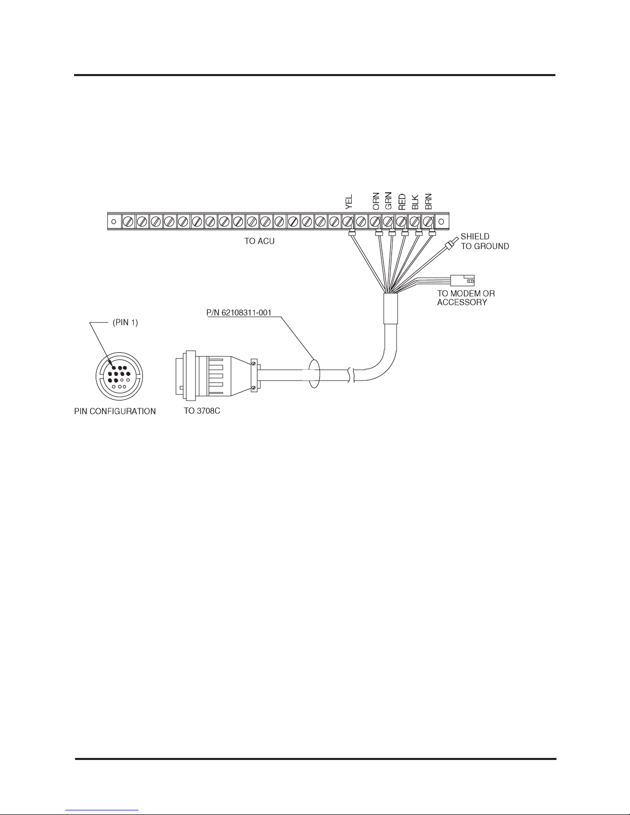
3.2.1 ACU CABLE CONNECTIONS
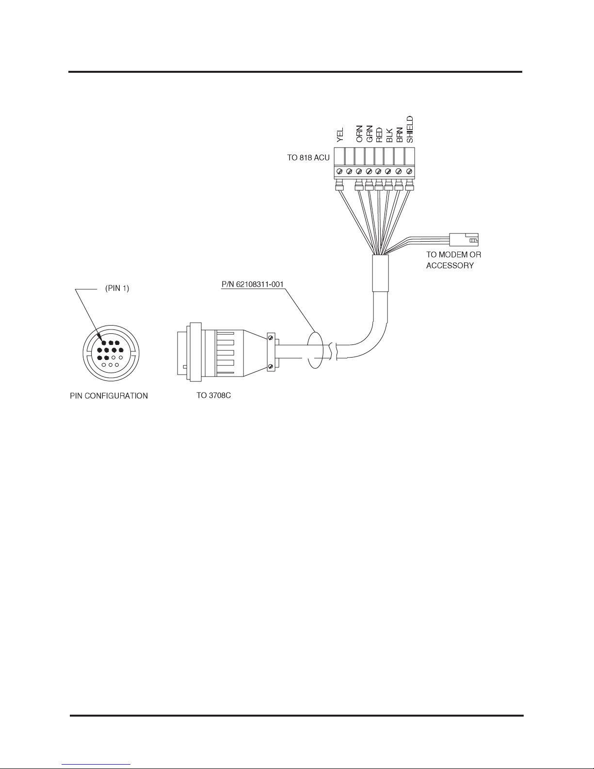
ACU Cable connections between the SE 3708C and the various ACU which it can power are shown
in Figure 3-1 and Figure 3-2, below.
Figure 3-1. SE 707, SE 718, SE 764S, SE 804, and SE 808 ACU Cable Connections
SE 3708C 3-2 66108566001-Rev. B
Page 19
Installation Introduction
Figure 3-2. SE 818 ACU Cable Connections
3.2.2 LOCK POWER WIRING CONNECTIONS
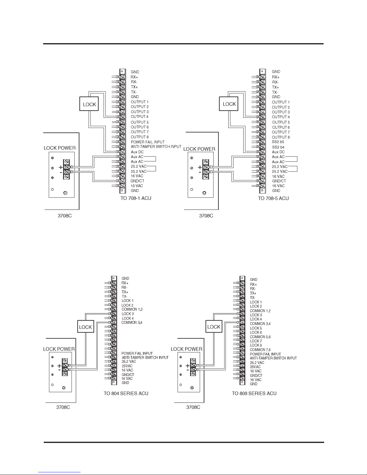
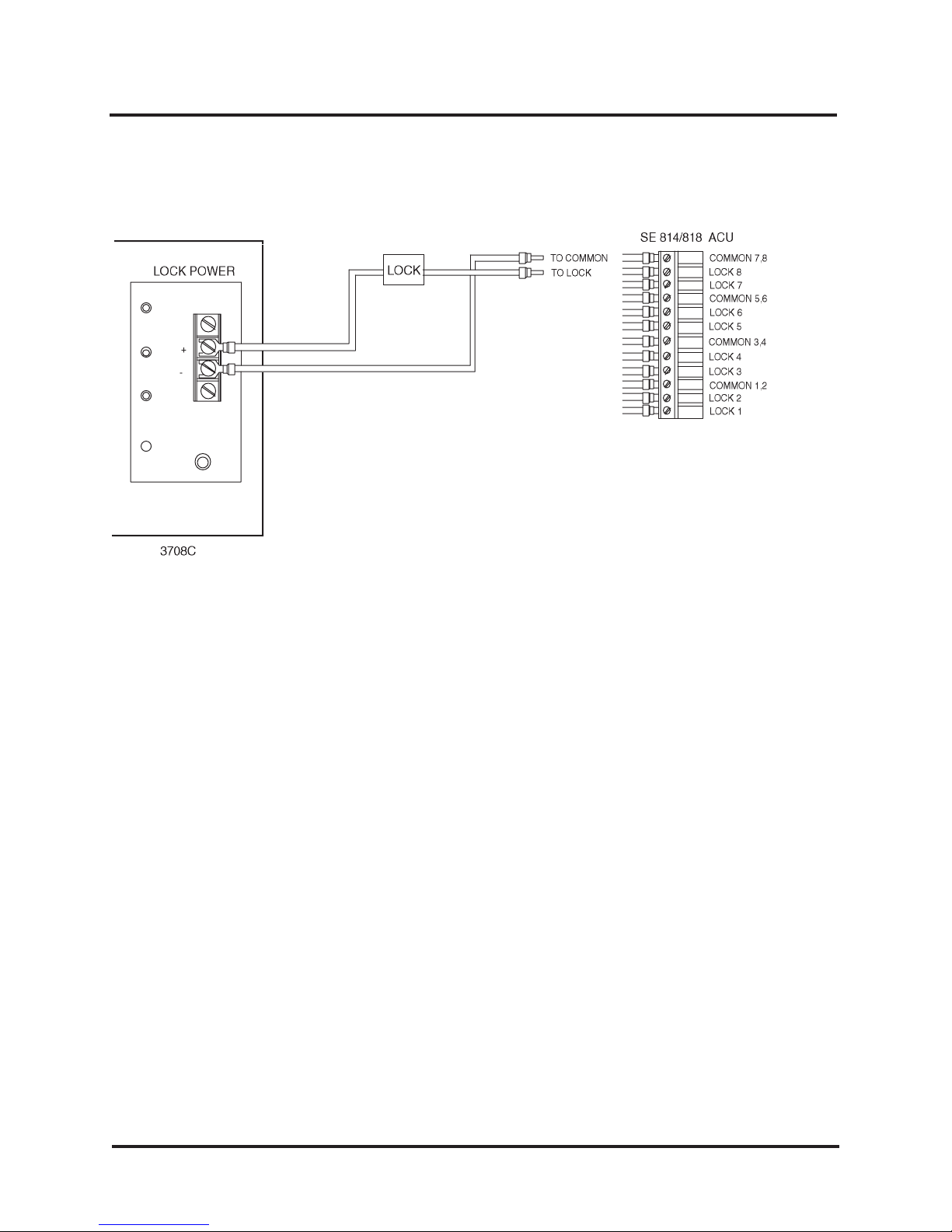
Wiring connections between the SE 3708C and the various ACUs it powers are shown in Figure 3-3,
Figure 3-4, and Figure 3-5, below.
66108566001-Rev. B 3-3 SE 3708C
Page 20
Installation SE 3708C Power Supply Manual
Figure 3-3. SE 708-1, SE 708-5, SE 718-1, and SE 718-5 Lock Power Connections
SE 3708C 3-4 66108566001-Rev. B
Page 21
Installation Introduction
Figure 3-4. SE 708P, SE 708S, SE 718P, SE 804, and SE 808 Lock Power Connections
Figure 3-5. SE 814/818SX Lock Power Connections
3.2.3 BATTERY CABLE CONNECTIONS
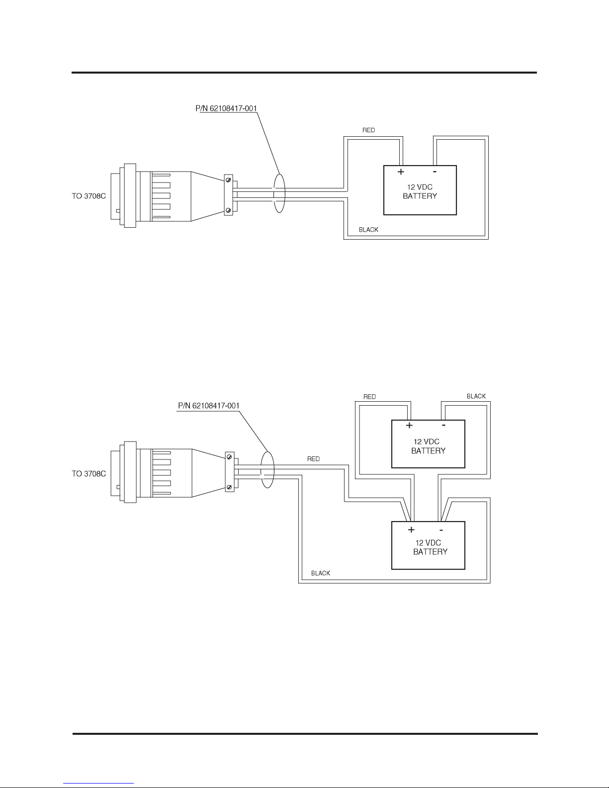
Connections between the SE 3708C and the various battery configurations using the Battery Cable
are shown below.
Battery Connections for SE 3708C Unit Configured for +12 VDC Lock Power
Battery connections for SE 3708C units that are configured to power +12 VDC Locks from one +12
VDC standby battery (see Table 1-1) are shown in Figure 3-6.
66108566001-Rev. B 3-5 SE 3708C
Page 22
Installation SE 3708C Power Supply Manual
Figure 3-6. Single Battery Connections for SE 3708C Unit
Powering +12 VDC Lock Power
Battery connections for SE 3708C units that are configured to power +12 VDC Locks from two +12
VDC standby batteries connected in parallel (see Table 1-1) are shown in Figure 3-7.
SE 3708C 3-6 66108566001-Rev. B
Figure 3-7. Parallel Battery Connections for SE 3708C Unit
Powering +12 VDC Lock Power
Page 23
Installation Introduction
Battery Connections for SE 3708C Unit Configured for +24 VDC Lock Power
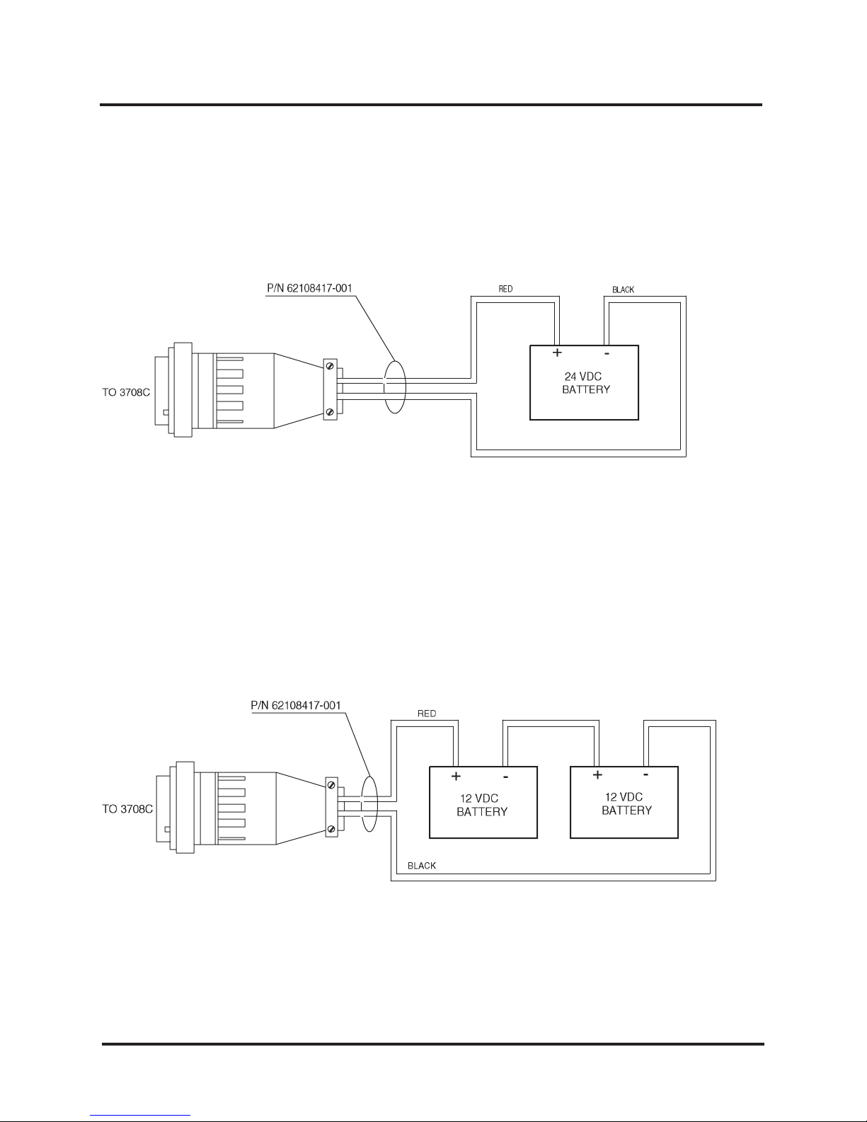
Battery connections for SE 3708C units that are configured to power +24 VDC Locks from one +24
VDC standby battery (see Table 1-1) are shown in Figure 3-8.
Series
Figure 3-8. Single Battery Connections for SE 3708C Unit
Powering +24 VDC Lock Power
Battery connections for SE 3708C units that are configured to power +24 VDC Locks from two +12
VDC standby batteries connected in series (see Table 1-1) are shown in Figure 3-9.
Figure 3-9. Series Battery Connections for SE 3708C Unit Powering +24 VDC
Locks Using Two +12 VDC Batteries Connected in
66108566001-Rev. B 3-7 SE 3708C
Page 24

Page 25

SECTION 4
TROUBLESHOOTING
Troubleshooting of the SE 3708C in the field is limited to checking continuity of the conductors in the
interface cables, analyzing probable fault conditions from the status of the LEDs, and replacing blown
fuses.
4.1 CUSTOMER SERVICE
If a problem with an SE 3708C occurs that can not be rectified by the replacement of a faulty cable or
interface wiring or a fuse, call WSE Customer Service for a Return Authorization. Units returned
without a Return Authorization will be refused.
Return faulty units to the following address:
Westinghouse Security Electronics
5452 Betsy Ross Drive
Santa Clara, CA 95054-1184
If you require a WSE Customer Support Technician for assistance, call the following phone number:
1-408-727-7170
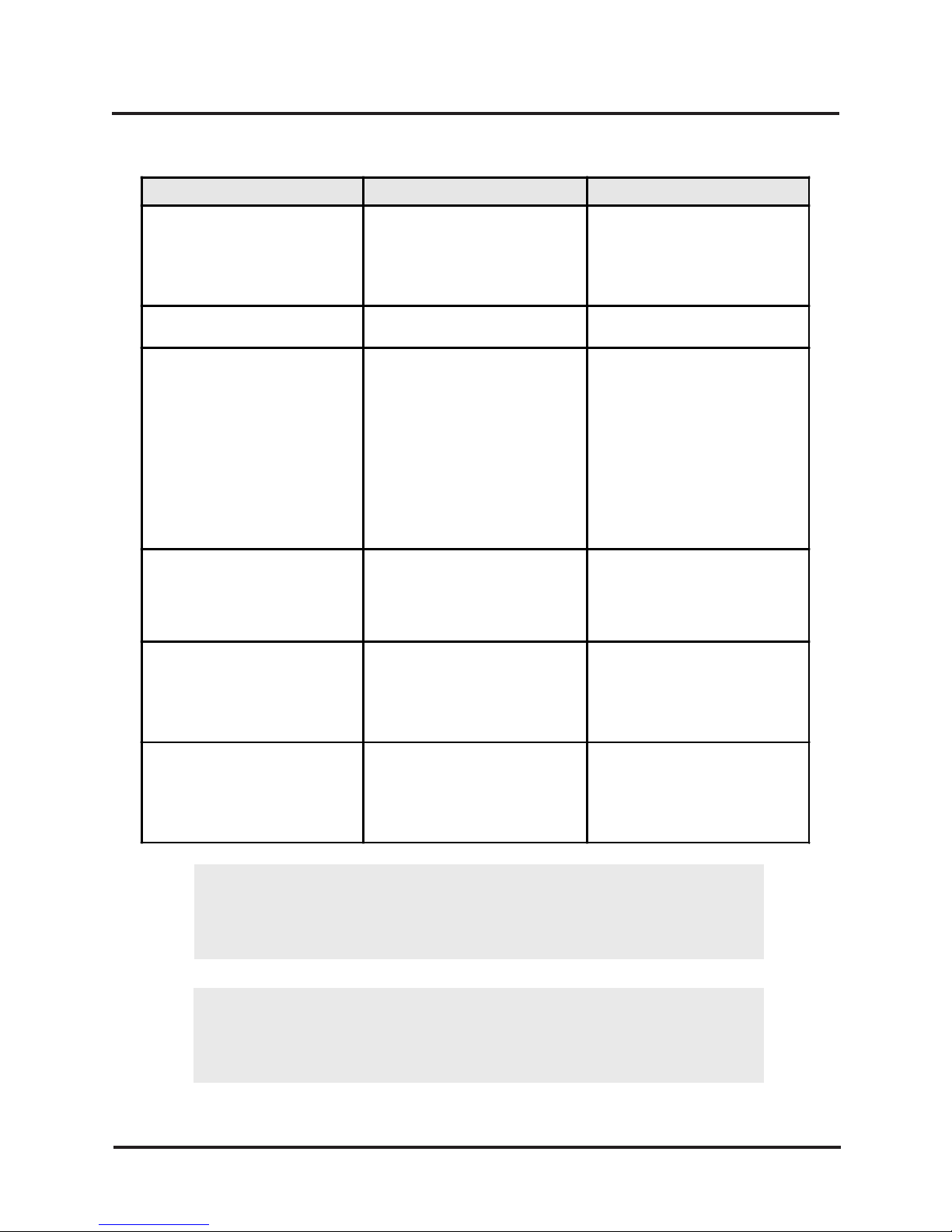
4-2 TROUBLESHOOTING GUIDE
A troubleshooting guide is provided in Table 4-1.
66108566001-Rev. B 4-1 SE 3708C
Page 26
Installation SE 3708C Power Supply Manual
p
p
(1)
(1)
plug
p
(2)
(2)
p
p
(1)
(1)
p
pp
y
(2)
(2)
g
g p
(1)
(1)
(2)
(2)
g p
g
(1)
(1)
g
(2)
y
(2)
y
(1)
(1)
(2)
(2)
y
Table 4-1. SE 3708C Troubleshooting Guide
Symptom Probable Cause Remedy
Pilot Light does not come on when
ON/OFF switch is
osition, but 400 Hz Inverter whines
and ACU Power LED is lit.
ACU receiv ing power, but no power
at locks
Pilot Light comes on when ON/OFF
switch is placed in the ON position,
but no lock
ower; 400 Hz Inverter does not
whine.
ht comes on when ON/OFF
Pilot Li
switch is placed in the ON position
and locks are receivin
ACU power; 400 Hz Inverter does
not whine.
ACU and Locks are receivin
but ACU receives POWER FAIL
e and BATT CONN LED is
mess a
out.
No AC line power and no power to
locks and ACU; no LEDs lit on unit
and no whine from Inverter.
laced in the ON
ower and no ACU
ower but no
ower
No AC power to unit.
Line Fuse is blown.
Lock Fuse is blown. Replace Lock Fuse; if fuse blows
Low Voltage Master Fuse is
blown.
Low Voltage Switching Power
Supply is faulty.
Inverter Fuse is blown.
400 Hz Inverter is faulty.
No AC to unit and Battery Fuse is
blown.
No AC to unit and standb
batteries are nearing discharge.
Battery Fuse is blown.
Standby Batteries are dead.
Check AC line; verify that Power
Cable
ower connector.
again, return unit to WSE.
again, return unit to WSE.
on right side of unit; disconnect
LOCK PWR terminals. Re
Volt age Master Fuse; if fuse blows
again or if whine is not heard from
Inverter, return unit to WSE. If fuse
does not blow and unit a
function normall
system wiring.
blows again, return unit to WSE.
blows a
BATT RESET switch to connect fresh
batteries to s
blows again, return unit to WSE.
BATT RESET switch to connect fresh
batteries to s
is plugged fully into
Replace Line Fuse; if fuse blows
Disconnect two round connectors
lace Low
ears to
, check ACU and
Return unit to WSE.
Replace Inverter Fuse; if fuse
Return unit to WSE.
Replace Batt ery Fus e; if fuse
ain, return unit to WSE.
Replace standby batteries; press
stem.
Replace Batt ery Fus e; if fuse
Replace standby batteries; press
stem.
DISCONNECT SUPPLY BEFORE CHANGING FUSE
COUPER LALIMENTATION AVANT DE REMPLACER LES FUSIBLES
SE 3708C 4-2 66108566001-Rev. B
CAUTION
ATTENTION
Page 27

APPENDIX A
SPECIFICATIONS
MECHANICAL
Size: 18.0 in. x 7.2 in. x 5.2 in. (45.7 cm x 18.3 cm x 13.2 cm)
Weight: 16 lbs (7.3 kg)
ENVIRONMENTAL
Temperature: 20°F to 120° F (-7° C to 49° C)
Humidity: 0% to 95% (non-condensing)
AC INPUTS/OUTPUTS
AC Input: 120.±10 or 230±20 volts AC, 50 or 60 Hz, single phase, 160 watts typical op-
erating conditions. Fused to 2 amps(115 volts), or 1 amp (230 volts)
AC Output: 400 Hz square wave AC, 2 amps at nominal 18.38 volts, center tapped 1 amp at
nominal 28.99 volts, center tapped 0.1 amp at 15.56 volts
DC INPUTS/OUTPUTS
DC Input: DC from gel cell or sealed lead acid batteries, rated between 20 and 40 amp hrs. For
12-volt systems, this can be a single 12-volt, 40 Ah battery, or two identical 12-volt, 20
Ah batteries connected in parallel. For 24-volt systems, this can be a single 20 Ah
battery, or two identical 12-volt, 20 Ah batteries connected in series.
DC Output: Up to 4 amps of lock power at 12 volts DC, or up to 3 amps of lock power at 24 volts
DC.
66108566001-Rev. B A-1 SE 3708C
Page 28

Page 29
)
)
)
)
APPENDIX B
SE 3708 VERSIONS
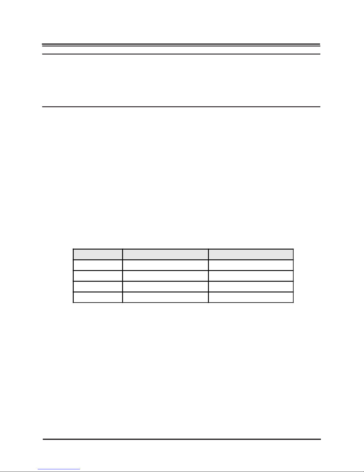
Differences between the four existing versions of the SE 3708 Uninterruptable Power Module are listed
in Table B and summarized as follows:
SE 3708: System power cord is attached to unit.
SE 3708A: System power cord is removable and connects to unit via a Molex
connector.
SE 3708B: System power cord connects to unit via round 14-pin connector. Battery power connects
to unit via round 4-pin connector.
SE 3708C: Input voltage select feature deleted. Unit has improved line filter (not externally vis-
ible).
Table B. SE 3708 Uninterruptable Power Module Versions
Vers ion System Power Cable Power Entry Module
SE 3708
SE 3708A Molex (removable
SE 3708B
SE 3708C Round 14-pin (removable
Molex (attached
Round 14-pin (removable
Wafer-selectable
Wafer-selectable
Wafer-selectable
Non-selectable
66108566001-Rev. B B-1 SE 3708C
Page 30

 Loading...