

Page 1
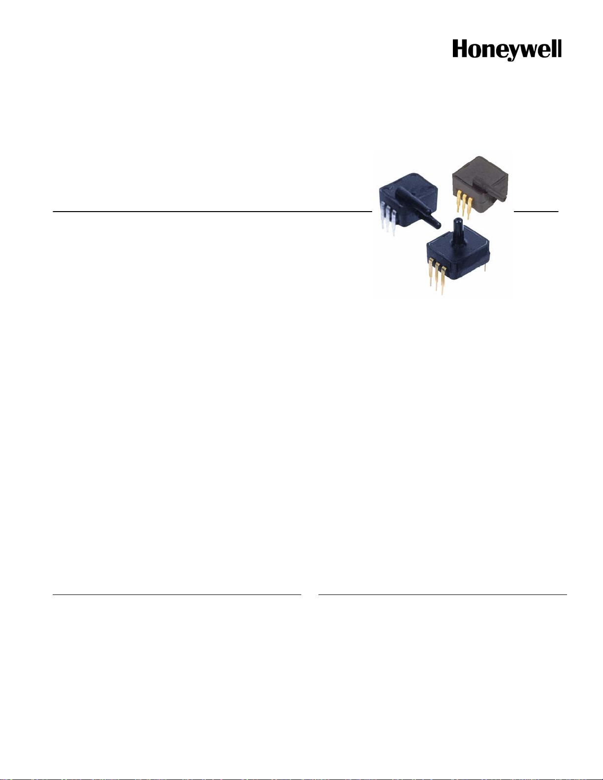
SDX Series
Plastic Silicon Pressure Sensors
Low Cost, Temperature
Compensated, DIP, 0 psi to 1 psi,
0 psi to 100 psi
DESCRIPTION
The SDX Series sensors provide a very cost-effective solution
for pressure applications that require small size plus
performance. These calibrated and temperature-compensated
sensors give an accurate and stable output over a 0 °C to 50
°C [32 °F to 122 °F] temperature range. This series is intended
for use with non-corrosive, non-ionic working fluids such as air
and dry gases.
Devices are available to measure absolute and gage pressures
from 1 psi (SDX01) up to 100 psi (SDX100). The absolute
devices have an internal vacuum reference and an output
voltage proportional to absolute pressure. The SDX devices
are available in standard commercial and prime grades
(SDCXXXXX-A) to allow optimization of accuracy and cost in
any given application.
FEATURES
• Low cost DIP
• Precision temperature compensation
• Calibrated zero and span
• Small size
• Low noise
• High impedance for low power applications
• Prime grade available (SDXxxxyy-A)
The SDX devices feature an integrated circuit (IC) sensor
element and laser trimmed thick film ceramic housed in a
compact solvent resistant case. The package is a double-wide,
dual-inline package (DIP). This is the same familiar package
used by IC manufacturers except it is only 11,94 mm [0.470 in]
long and has a pressure port(s). The PC board area used by
each DIP is approximately 0.26 in
enables the use of multiple sensors in limited available space.
The DIP provides excellent corrosion resistance and isolation
to external package stress.
The DIP mounts on a PC board like a standard IC with
through-hole pins. The pins anchor the pressure sensor to the
PC board and provide a more secure and stable unit than other
types of packages.
The output of the bridge is ratiometric to the supply voltage and
operation from any dc supply voltage up to 20 Vdc is
acceptable.
POTENTIAL APPLICATIONS
• Medical equipment
• Computer peripherals
• Pneumatic controls
• HVAC
2
. This extremely small size
Page 2
SDX Series
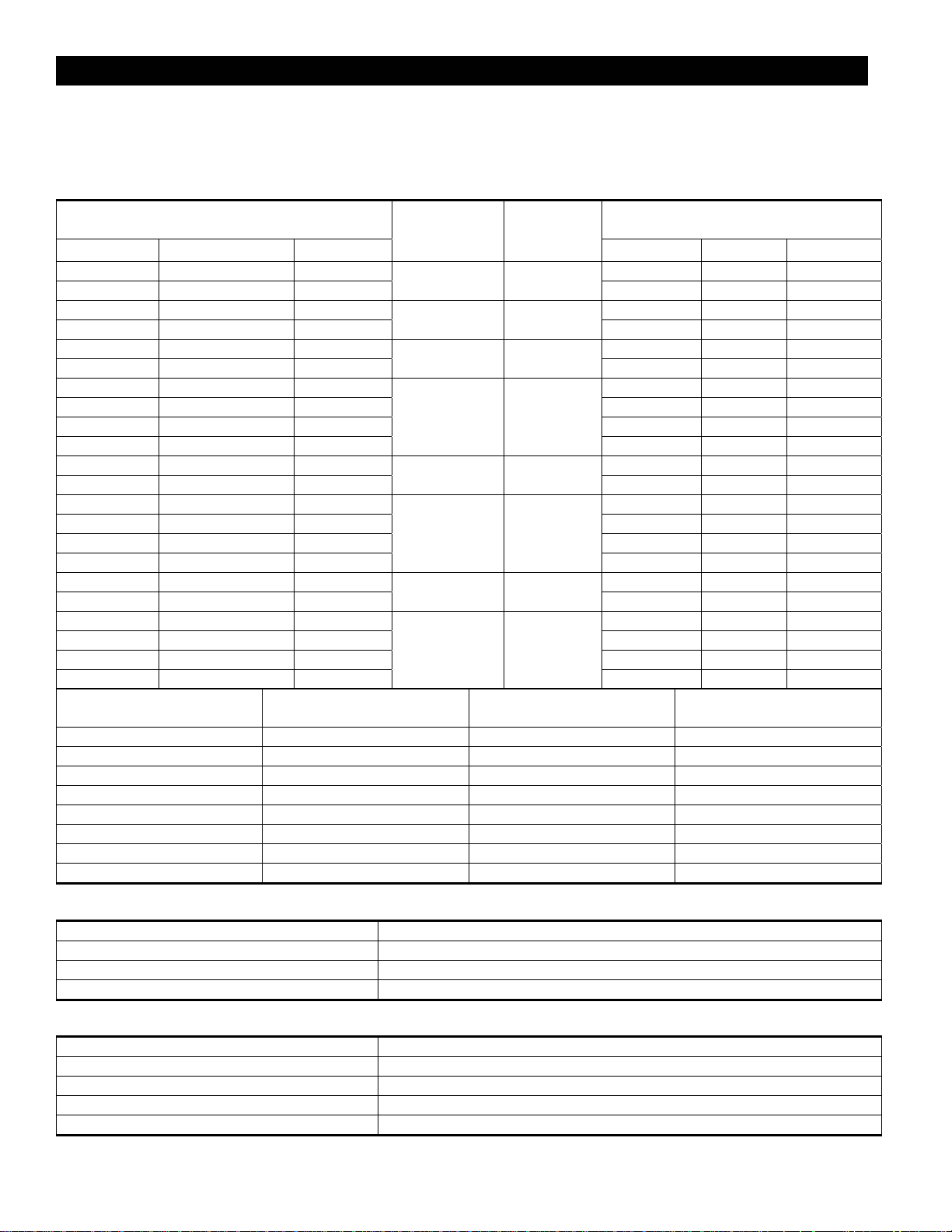
Table 1. Pressure Range Specifications and Ordering Information
Catalog Listing, Pressure Connection,
Pressure Type
Gage Differential/Gage Absolute
SDX01G2 SDX01D4
SDX01G2-A SDX01D4-A
SDX05G2 SDX05D4
SDX05G2-A SDX05D4-A
SDX15G2 SDX15D4
SDX15G2-A SDX15D4-A
- - SDX15A2 86.85 mV 90.00 mV 93.15 mV
- - SDX15A4 86.85 mV 90.00 mV 93.15 mV
- - SDX15A2-A 89.10 mV 90.00 mV 90.90 mV
- - SDX15A4-A
SDX30G2 SDX30D4
SDX30G2-A SDX30D4-A
- -
- -
- -
- -
SDX100G2 SDX100D4
SDX100G2-A SDX100D4-A
- -
- -
- -
- -
Nomenclature Pressure Connection
G2 A2/G2 gage standard commercial
G2-A A2/G2 gage prime
D4 OK differential standard commercial
D4-A OK differential prime
A2 A2/G2 absolute standard commercial
A2-A A2/G2 absolute prime
A4 A4 absolute standard commercial
A4-A A4 absolute prime
-
-
-
-
-
-
-
-
SDX30A2 86.85 mV 90.00 mV 93.15 mV
SDX30A4 86.85 mV 90.00 mV 93.15 mV
SDX30A2-A 89.10 mV 90.00 mV 90.90 mV
SDX30A4-A
-
-
SDX100A2 96.50 mV 100.00 mV 103.5 mV
SDX100A4 96.50 mV 100.00 mV 103.5 mV
SDX100A2-A 99.00 mV 100.00 mV 101.0 mV
SDX100A4-A
(See Fig. 2)
Operating
Pressure
0 psid to 1 psid 20 psid
0 psid to 5 psid 20 psid
0 psid to 15 psid 30 psid
0 psia to 15 psia 30 psia
0 psid to 30 psid 60 psid
0 psia to 30 psia 60 psia
0 psid to 100
psid
0 psia to 100
psia
Proof
Pressure
150 psid
150 psia
Pressure Type Grade
(2)
17.37 mV 18.00 mV 18.18 mV
17.82 mV 18.00 mV 18.80 mV
57.90 mV 60.00 mV 62.10 mV
59.40 mV 60.00 mV 60.60 mV
86.85 mV 90.00 mV 93.15 mV
89.10 mV 90.00 mV 90.90 mV
89.10 mV 90.00 mV 90.90 mV
86.85 mV 90.00 mV 93.15 mV
89.10 mV 90.00 mV 90.90 mV
89.10 mV 90.00 mV 90.90 mV
96.50 mV 100.00 mV 103.5 mV
99.00 mV 100.00 mV 101.0 mV
99.00 mV 100.00 mV 101.0 mV
Full-Scale Span
Min. Typ. Max.
Table 2. General Specifications (Maximum)
Characteristic Parameter
Supply voltage (VS) 20 Vdc
Common mode pressure 150 psig
Lead soldering temperature (2 s to 4 s) 250 °C [482 °F]
Table 3. Environmental Specifications (Maximum)
Characteristic Parameter
Compensated operating temperature 0 °C to 50 °C [32 °F to 122 °F]
Operating temperature -40 °C to 85 °C [-40 °F to 185 °F]
Storage temperature -55 °C to 125 °C [-67 °F to 257 °F]
Humidity limits 0% RH to 100% RH
(1)
2 www.honeywell.com/sensing
Page 3
Plastic Silicon Pressure Sensors, Low Cost, Temperature
Compensated, DIP, 0 psi to 1 psi, 0 psi to 100 psi
Table 4. Performance Characteristics
(3)
Characteristic Min. Typ. Max. Unit
Zero pressure offset
Zero pressure offset (prime grade)
Combined linearity and hysteresis
Combined linearity and hysteresis (prime grade)
(4)
(5)
(5) (13)
Temperature effect on span, 0 °C to 50 °C [32 °F to 122 °F]
Temperature effect on span, 0 °C to 50 °C [32 °F to 122 °F]
Temperature effect on offset 0, °C to 50 °C [32 °F to 122 °F]
Temperature effect on offset 0, °C to 50 °C [32 °F to 122 °F]
Repeatability
Input resistance
Output resistance
Common mode voltage
Response time
Long term stability of offset and span
(7)
(8)
(9)
(10)
(11)
(12)
(6)
(6)
(prime grade)
(6)
(6)
(prime grade)
-1.0
-0.3
–
–
–
–
–
–
0.0
0.0
±0.2
±0.1
±0.4
±0.4
±0.2
±0.2
+1.0
0.3
±1.0
±0.25
±2.0
±1.0
±1.0
±0.5
– ±0.2 ±0.5 % FSO
– 4.0 – kOhm
– 4.0 – kOhm
1.5 3.0 5.0 Vdc
– 100 – µs
– ±0.1 – mV
mV
mV
% FSO
% FSO
% FSO
% FSO
mV
mV
Notes:
1. Full-Scale Span is the algebraic difference between the output voltage at full-scale pressure and the output at zero pressure.
Full-Scale Span is ratiometric to the supply voltage.
2. Maximum pressure above which causes permanent sensor failure.
3. Reference conditions:
T
•
= 25 °C (unless otherwise noted).
A
• Supply V
• Pressure applied to
= 12 Vdc, Common Mode Line pressure = 0 psig.
S
Port B. For absolute devices only, pressure is applied to Port A and the output polarity is reversed.
4. Maximum zero pressure offset for absolute devices is ±500 mV.
5. Hysteresis is the maximum output difference at any point within the operating pressure range for increasing and decreasing
pressure.
6. Maximum error band of the offset voltage and the error band of the span, relative to the 25 °C [77 °F] reading.
7. Maximum difference in output at any pressure within the operating pressure range and the temperature within 0 °C to 50 °C
[32 °F to 122 °F] after:
• 100 temperature cycles, 0 °C to 50 °C [32 °F to 122 °F].
• 1.0 million pressure cycles, 0 psi to full-scale span.
8. Input resistance is the resistance between V
9. Output resistance is the resistance between the + and - outputs.
10. Common Mode voltage of the output arms for V
11. Response time for a 0 psi to Full-Scale Span pressure step change, 10% to 90% rise time.
and ground.
S
=12 Vdc.
S
12. Long term stability over a one-year period.
13. Maximum combined linearity and hysteresis for the SDX05 prime grade is ±0.5%.
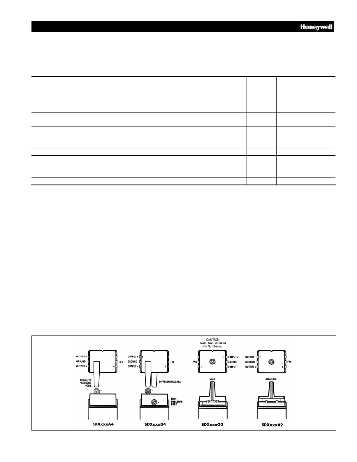
Figure 1. Electrical Connections
Honeywell Sensing and Control 3
Page 4
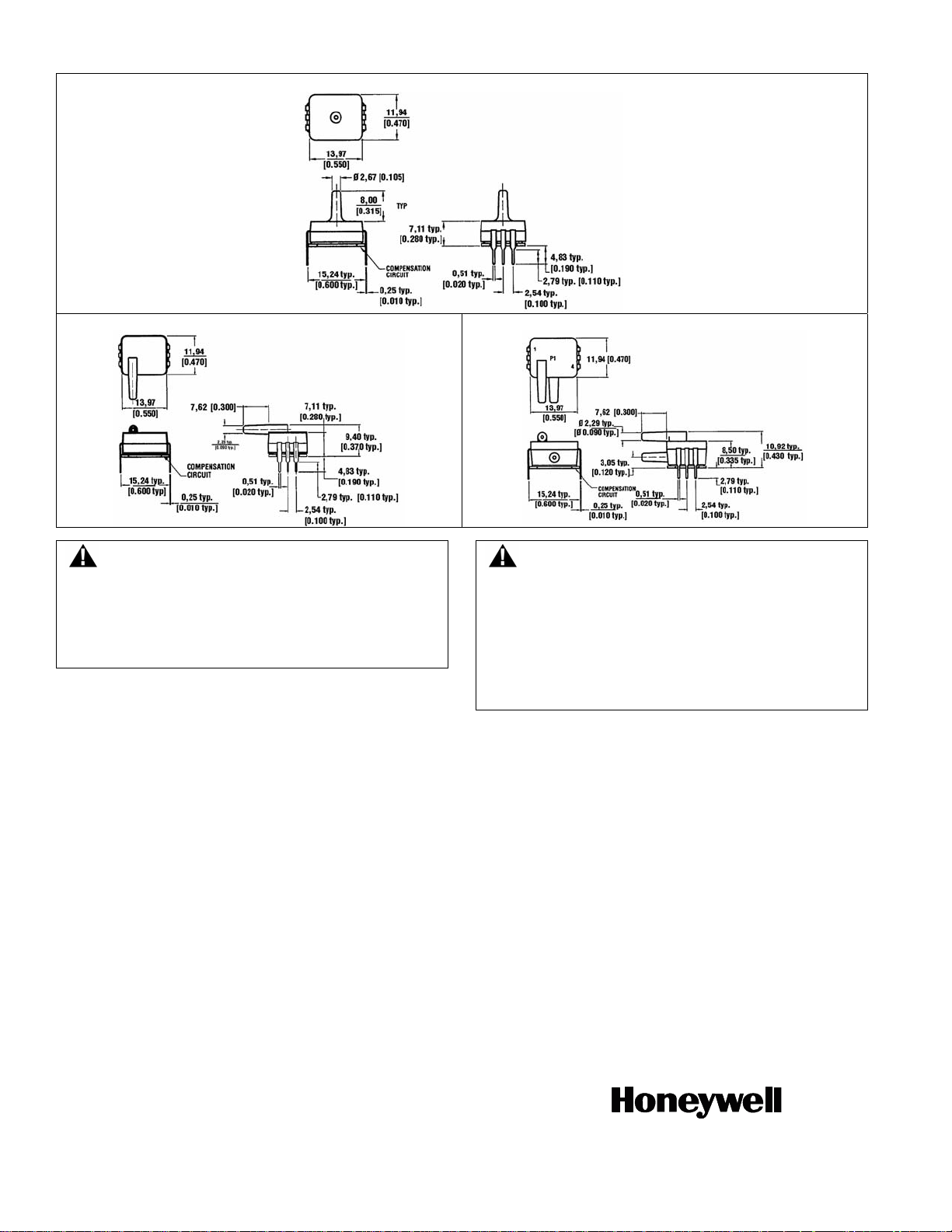
Figure 2. Mounting Dimensions (For Reference Only. mm/[in])
A2/G2 Package
A4 Package D4 Package
WARNING
PERSONAL INJURY
DO NOT USE these products as safety or emergency stop
devices or in any other application where failure of the
product could result in personal injury.
Failure to comply with these instructions could result
in death or serious injury.
WARRANTY/REMEDY
Honeywell warrants goods of its manufacture as being free of
defective materials and faulty workmanship. Honeywell’s
standard product warranty applies unless agreed to otherwise
by Honeywell in writing; please refer to your order
acknowledgement or consult your local sales office for specific
warranty details. If warranted goods are returned to Honeywell
during the period of coverage, Honeywell will repair or replace,
at its option, without charge those items it finds defective. The
foregoing is buyer’s sole remedy and is in lieu of all other
warranties, expressed or implied, including those of
merchantability and fitness for a particular purpose. In no
event shall Honeywell be liable for consequential, special,
or indirect damages.
While we provide application assistance personally, through
our literature and the Honeywell web site, it is up to the
customer to determine the suitability of the product in the
application.
supply is believed to be accurate and reliable as of this
printing. However, we assume no responsibility for its use.
MISUSE OF DOCUMENTATION
• The information presented in this product sheet is for
reference only. Do not use this document as a product
installation guide.
• Complete installation, operation, and maintenance
information is provided in the instructions supplied with
each product.
Failure to comply with these instructions could result in
death or serious injury.
SALES AND SERVICE
Honeywell serves its customers through a worldwide network
of sales offices, representatives and distributors. For
application assistance, current specifications, pricing or name
of the nearest Authorized Distributor, contact your local sales
office or:
E-mail: [email protected]
Internet: www.honeywell.com/sensing
Phone and Fax:
Asia Pacific +65 6355-2828; +65 6445-3033 Fax
Europe +44 (0) 1698 481481; +44 (0) 1698 481676 Fax
Latin America +1-305-805-8188; +1-305-883-8257 Fax
USA/Canada +1-800-537-6945; +1-815-235-6847
+1-815-235-6545 Fax
Specifications may change without notice. The information we
WARNING
Sensing and Control
Honeywell
1985 Douglas Drive North
Golden Valley, Minnesota 55422
www.honeywell.com/sensing
008103-3-EN IL50 GLO Printed in USA
November 2008
Copyright © 2008 Honeywell International Inc. All rights reserved.
 Loading...