

Honeywell SC105 Installation & User Manual

Honeywell
Mini-Seismic Vibration Detector SC105
Planning and Installation
User Guide
To get the best use of the product, please read the User Guide carefully before using the product.
Keep the User Guide at an easily accessible place and make it available to the next user.
© 2010 Honeywell International Inc. All rights reserved.
http://www.security.honeywell.com/
Document 800-04997 Rev. A

Honeywell
i
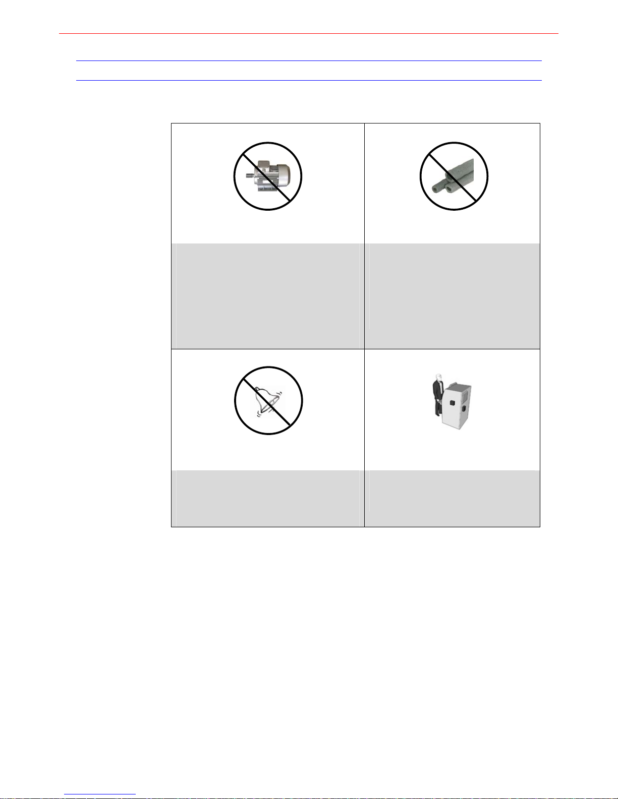
TO THE INSTALLER
Before planning and installing Seismic Vibration Detector SC100, the circumstances below should
be avoided:
Electrical Devices
Water piping
Do not apply the detectors close to electrical
devices (such as electric motors, transformers,
fans, air conditioners and so on), which may
create mechanical vibrations in the protected
structure.
Avoid mechanical contact between such
devices and the protected surface, or using
appropriate insulating materials to reduce the
vibrations.
Do not apply the detectors close to water
piping.
The flow of water through piping, when in
mechanical contact with the protected
structure, emits a strong signal in the
structure itself, which may cause nuisance
alarms.
Bells
Human activity
Do not apply the detectors close to the bells;
Or apply a piece of tape on the bell to suppress
the overtones generated in the frequency range
of the detectors.
Apply carpet or vibration damping material
on vaults and under safes placed on
concrete or marble floors.
Regular maintenance and inspection (at least annually) by the installer and frequent testing by the
user are vital to continuous satisfactory operation of any product.
The installer should assume the responsibility of developing and offering a regular maintenance
program to the user, as well as acquainting the user with the proper operation and limitations of
the product and its component parts. Recommendations must be included for a specific program
of frequent testing to insure the product’s operation at all times.

Honeywell
ii
LIMITED WARRANTY
Honeywell International Inc., acting through its Security & Custom Electronics business ("Seller")
165 Eileen Way, Syosset, New York 11791, warrants its product(s) to be in conformance with its
own plans and specifications and to be free from defects in materials and workmanship under
normal use and service for 24 months from the date stamp control on the product(s) or, for
product(s) not having a manufacturer’s date stamp, for 12 months from date of original purchase
unless the installation instructions or catalog sets forth a shorter period, in which case the shorter
period shall apply. Seller's obligation shall be limited to repairing or replacing, at its option, free of
charge for materials or labor, any product(s) which is proved not in compliance with Seller's
specifications or proves defective in materials or workmanship under normal use and service.
Seller shall have no obligation under this Limited Warranty or otherwise if the product(s) is altered
or improperly repaired or serviced by anyone other than Honeywell factory service. For warranty
service, return product(s) transportation prepaid, to Honeywell Factory Service, 165 Eileen Way,
Syosset, New York 11791.
THERE ARE NO WARRANTIES, EXPRESS OR IMPLIED, OF MERCHANTABILITY, OR
FITNESS FOR A PARTICULAR PURPOSE OR OTHERWISE, WHICH EXTEND BEYOND THE
DESCRIPTION ON THE FACE HEREOF. IN NO CASE SHALL SELLER BE LIABLE TO
ANYONE FOR ANY CONSEQUENTIAL OR INCIDENTAL DAMAGES FOR BREACH OF THIS
OR ANY OTHER WARRANTY, EXPRESS OR IMPLIED, OR UPON ANY OTHER BASIS OF
LIABILITY WHATSOEVER, EVEN IF THE LOSS OR DAMAGE IS CAUSED BY THE SELLER'S
OWN NEGLIGENCE OR FAULT.
Seller does not represent that the product(s) it sells may not be compromised or circumvented;
that the product(s) will prevent any personal injury or property loss by burglary, robbery, fire or
otherwise; or that the product(s) will in all cases provide adequate warning or protection.
Customer understands that a properly installed and maintained alarm system may only reduce
the risk of a burglary, robbery, fire,
or other events occurring without providing an alarm, but it is
not insurance or a guarantee that such will not occur or that there will be no personal injury or
property loss as a result. CONSEQUENTLY, SELLER SHALL HAVE NO LIABILITY FOR ANY
PERSONAL INJURY, PROPERTY DAMAGE OR OTHER LOSS BASED ON A CLAIM THAT
THE PRODUCT(S) FAILED TO GIVE WARNING. HOWEVER,
IF SELLER IS HELD LIABLE,
WHETHER DIRECTLY OR INDIRECTLY, FOR ANY LOSS OR DAMAGE ARISING UNDER THIS
LIMITED WARRANTY OR OTHERWISE, REGARDLESS OF CAUSE OR ORIGIN, SELLER'S
MAXIMUM LIABILITY SHALL NOT IN ANY CASE EXCEED THE PURCHASE PRICE OF THE
PRODUCT(S), WHICH SHALL BE THE COMPLETE AND EXCLUSIVE REMEDY AGAINST
SELLER.
This warranty replaces any previous warranties and is the only warranty made by Seller on this
product(s). No increase or alteration, written or verbal, of the obligations of this Limited Warranty
is authorized.

Honeywell
i
Contents
1 About This Document ......................................................................................................................................1
Overview of Contents ..............................................................................................................................1
Special Font and Symbols.......................................................................................................................1
How to Use This Document.....................................................................................................................1
2 Introduction ...................................................................................................................................................... 2
Overview of the Detector ......................................................................................................................... 2
Applications .............................................................................................................................................2
Features ..................................................................................................................................................3
3 Function Description ........................................................................................................................................ 4
Function Criteria ......................................................................................................................................4
Detection Parameters........................................................................................................................4
Alarm Criteria.....................................................................................................................................4
Function Modules ....................................................................................................................................4
Sensor Element .................................................................................................................................4
Signal Conditional Block....................................................................................................................4
Switch Block ......................................................................................................................................5
Micro Controller Block .......................................................................................................................5
Output Alarm Block............................................................................................................................5
Power Supply Block...........................................................................................................................5
Sabotage Protection .......................................................................................................................... 5
4 Basic Accessories............................................................................................................................................6
5 Planning Protections........................................................................................................................................7
Mini-ATMs ...............................................................................................................................................7
Vending Machines and Ticket Machines .................................................................................................7
6 Installation........................................................................................................................................................9
Mounting the Detector .............................................................................................................................9
Opening the Detector ........................................................................................................................9
Mounting on Steel..............................................................................................................................9
Mounting on Stainless Steel or Hardened Steel .............................................................................. 10
Mounting the Accessories .....................................................................................................................11
The Movable Mounting Kit SC111 ................................................................................................... 11
The Keyhole Protection Kit SC112 ..................................................................................................11
The Spacer for Keyhole Protection Kit SC118................................................................................. 11
The Armored Cable Kit SC114 ........................................................................................................12
The Test Transmitter SC113 ...........................................................................................................12
The External Test Transmitter SC115 .............................................................................................12
7 Settings.......................................................................................................................................................... 13
DIP Switch Settings...............................................................................................................................13
EOL Jumper Settings ............................................................................................................................14
J19/J20 Settings....................................................................................................................................14
J1 Setting ..............................................................................................................................................14
8 Connecting the Detector ................................................................................................................................15
9 Test................................................................................................................................................................16
Control and Function Test .....................................................................................................................16
Remote Test (Alternative)...................................................................................................................... 16
10 Technical Specifications ................................................................................................................................18

Honeywell
ii
Figures
Figure 2-1 Detector Description ...................................................................................................................................................... 2
Figure 5-1 Planning ATM Protection............................................................................................................................................... 7
Figure 5-2 Planning Vending Machine/Ticket Machine Protection .................................................................................................8
Figure 6-1 Opening the Detector ....................................................................................................................................................9
Figure 6-2 Drill Plan ........................................................................................................................................................................ 9
Figure 6-3 Mounting Plate SC110 - UPSIDE DOWN ................................................................................................................... 10
Figure 6-4 Movable Mounting Kit SC111 Components ................................................................................................................ 11
Figure 6-5 Keyhole Protection Kit SC112 Components................................................................................................................ 11
Figure 6-6 Spacer for Keyhole Protection Kit SC118 Components .............................................................................................. 11
Figure 6-7 Armored Cable Kit SC114 ........................................................................................................................................... 12
Figure 6-8 Test Transmitter SC113 ..............................................................................................................................................12
Figure 6-9 External Test Transmitter SC115 Components........................................................................................................... 12
Figure 7-1 Function modules on Detector Base ...........................................................................................................................13
Figure 8-1 Wirings on the terminal block ......................................................................................................................................15
Figure 8-2 Alarm and tamper configured to one loop ...................................................................................................................15
Figure 8-3 Alarm and tamper configured to two loops.................................................................................................................. 15

Honeywell
iii
Tables
Table 2-1 Application Settings ........................................................................................................................................................ 2
Table 9-1 Remote Test ................................................................................................................................................................. 17


Honeywell
- 1 -
1 About This Document
Thank you for purchasing Honeywell Mini-Seismic Vibration Detector SC105!
This guide is designed to be a reference for the planning and installation of Mini-Seismic Vibration
Detector SC105.
Overview of Contents
This document contains the following chapters:
Chapter 1, About This Document, gives a brief introduction of “Mini-Seismic Vibration
Detector SC105 Planning and Installation User Guide”.
Chapter 2, Introduction, general information about Mini-Seismic Vibrati
on Detector SC105,
applications and features.
Chapter 3, Function Description, introduces the function criteria a
nd function modules of
Mini-Seismic Vibration Detector SC105.
Chapter 4, Basic Accessories , lists all basic
accessories will be used with Mini-Seismic
Vibration Detector SC105.
Chapter 5, Planning Protections, gives an instruction on planning Mini-Seismic Vibration
Detector SC1
05 on different applications.
Chapter 6, Installation, introduces how to install Mini-Seismic Vibration Detector SC105 and
related access
ories.
Chapter 7, Settings, shows how to configure sensitivities and other settings on Mini-Seismic
Vibrati
on Detector SC105 base.
Chapter 8, Connecting the Detector, introduces how to wire and connect Mini-Seismic
Vibrati
on Detector SC105 to the protected zone.
Chapter 9, Test, introduces the tests of the Mini-Se
ismic Vibration Detector SC105.
Chapter 10, Technical Specifications, introduces technical specification of Mini-Seismic
Vibrati
on Detector SC105.
Special Font and Symbols
Italic
references
Note
the important notice should pay attention to
Caution
important operating alerted
How to Use This Document
Pictures in the manual are for reference only, so please see the actual items.
The products will be updated and the information shall not be distributed.
Please read the book before operation and keep it properly for future use.
The manual has been reviewed and the accuracy is guaranteed. If there is any uncertainty
or controversy, please refer to the final explanation of Honeywell. Honeywell does not take
any responsibility for any consequences caused by misunderstanding of the manual or
improper operations.
 Loading...