

Honeywell SC100 Seismic Vibration Detector
Installation Guide
1. General Information
SC100 Seismic Vibration Detector is a universal seismic or structural vibration detector designed to d etect selected vibrations
from burglary or intrusion attempt to high value storage units, such as Vaults, Door s, ATMs, Safes and other solid structures.
The detector consists of a sensor to convert mechanical vibrations to electrical signals, a sig nal conditioning block, signal
analysis and alarm criteria blocks, output alarm circuits, tamper protection, and a switching block for selecting detector
settings, all in a miniature metal housing.
This Installation Guide provides general information about the mounting and confi guring of SC100 Seismic Vibration Detector.
For more details, such as planning detector locations, please refer to “SC100 Seismic Vibra tion Detector Planning and
Installation Guide”.
2. Applications
SC100 Seismic Vibration Detector is designed to detect any known attack tool on :
Vault Doors
ATMs
Night Deposit Safes
Strong Room Vaults
Modular Vaults
Free Standing Safes
Hatches
Gates
Chests
Other objects with a solid structure
2.1 Application Settings
Sensitivity
Settings
Material
Detection
Radius
Applications Noise Level
G
high
Concrete 5.0m
Strong Room Vaults, Vault Doors, Modular Vaults,
Safes and ATMs (advised for grade 4 to 6)
Insignificant noise level
Concrete 2.5m
G
normal
Steel 4.0m
Strong Room Vaults, Vault Doors, Modular Vaults,
Safes and ATMs
Moderate noise level
Concrete 1.5m
G
low
Steel 2.0m
Safes, Night Deposit Safes, ATMs and Chests Considerable noise level
G
noisy
Steel 1.5m
Safes, Night Deposit Safes, ATMs and chests with
excessive noise (internal or external)
Heavy noise level
Notes:
1. Sensitivity settings (G
high
, G
normal
, G
low
, G
noisy
) are defined in “4.2.1 DIP Switch Settings”.
2. The parameters in the table above are only for reference, and they may vary according to the quality of the material.
3. The detection range will be reduced if cracks and joints exist in the material.
3. Mounting the Detector
SC100 Seismic Vibration Detector can be mounted on any solid surface, of which t he most common surfaces are: Steel,
Stainless Steel, Hardened Steel and Concrete.
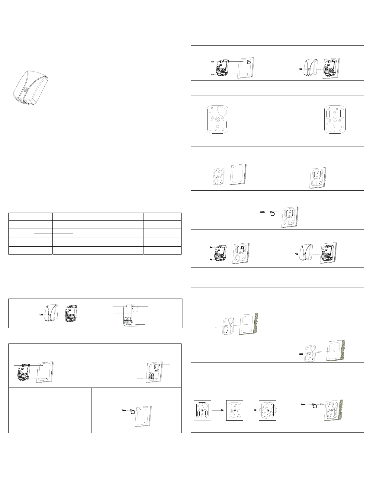
3.1 Opening the Detector
Before mounting the detector, separate the detector cover from the detector base first (by loosing the top screw, see Figure 1).
Figure 1 Open the detector
Detector Cover Detector Base
Figure 2 Drill Plan
NotePl ease r emove the drill
:
planaftermounting holes
havebeendrille d
3.2 Mounting on Steel
When mounting the detector on a flat and smooth steel surface, both Drill Plan (see Figure 2) and Detector Base can be used
to mark the mounting holes.
1. Remove and clean paint from the mounting area.
2. Attach the detector base or drill plan on the mounting area, then mark the outline and center punch the detector
mounting holes A, B and Test Transmitter SC113 mounting hole C.
A
B
Notes:
Detector base cannot be used to mark Test
Transmitter SC113 mounting hole C.
Skip marking hole C if Test Transmitter
SC113 is not used.
C
A
B
3. Drill the detector mounting holes A, B (Ø 3.3mm and
minimum 8 mm deep), and then thread the two holes
with a M4 Tap (6mm at least).
4. Drill the Test Transmitter SC113 mounting hole C (Ø
3.3mm and minimum 8 mm deep), and then thread
the hole with a M4 Tap (6mm at least).
5. Remove the dill plan and all of the burrs.
Notes:
Cool the tools with oil while drilling and threading.
Skip step 4 if Test Transmitter SC113 is not used.
6. Attach Test Transmitter SC113 on the mounting area (at
C) and then use the M4×8mm screw to fix it.
Note: Skip this step if Test Transmitter SC113 is not used.
C
7. Attach the detector base on the steel surface and
then use the two M4×8mm screws provided to fix it.
8. Wire and configure the detector (see “4. Wirings and
Settings”), and then use the top screw to fix the detector
cover properly.
24-hour surveillance of vaults, doors, safes, ATMs and other high value
storage units
Flat frequency response sensor for genuine signal analysis
DIP switch sensitivity settings
Noise sensitivity settings using built-in diagnostic tool
Integrated EOL resistors
High detection capability
Low current consumption
Standard drill sheet protection
Miniature metal housing – easy to fit in restricted spaces
3.3 Mounting on Stainless Steel or Hardened Steel
When mounting on stainless steel or hardened steel, Mounting Plate SC110 (UPSIDE DOWN, see Figure 4) must be used
and should be welded on the mounting surface first.
Figure 3 Mounting Plate SC110
UPSIDE
F
G
C
D
E
A
B
This orientation is used for mounting
on concrete.
A, B – Detector SC100 mounting hole
C, D, – Test Transmitter SC113 locating hole
E – Mounting Plate SC110 mounting hole
F, G – Welding Slots
Figure 4 Mounting Plate SC110
UPSIDE DOWN
FG
C
D
E
A
B
This orientation is used for mountin g on
stainless steel or hardened steel.
1. Remove paint from the mounting area
(especially welding area).
2. Attach
Mounting Plate SC110 on the mounting
area, and then mark the outline.
3. Fix
Mounting Plate SC110 into the outline marked and ensure it
cannot move, and then along the INSIDE of the welding slots
weld
Mounting Plate SC110 on the mounting surface.
Note: The welding must be done along the INSIDE of the welding
slots, otherwise
Mounting Plate SC110 can be deformed.
4. Tap off slag and remove weld spatter and make sure th e whole mounting surface is still flat.
5. Attach Test Transmitter SC113 on Mounting Plate SC110 (at C) and then use the M4×8mm screw to fix it.
Note: Skip this step if
Test Transmitter SC113 is not used.
C
6. Attach the detector base on Mounting Plate
SC110 and then use the two M4×8mm screws
provided to fix it.
7. Wire and configure the detector (see “4. Wirings and
Settings”), and then use the top screw to fix the detector cover
properly.
3.4 Mounting on Concrete
When mounting on concrete, Mounting Plate SC110 (UPSIDE, see Figure3) must be used.
Note: Mounting directly on a bare or plastered concrete surface may result in low detection sensi tivity and cause damage to
the detector.
1. Attach
Mounting Plate SC110 on the mounting area and
then mark the outline and center hole E.
2. Drill the center hole E of Ø 10mm and minimum 65mm
deep, and then remove all drill residuals and plaster.
E
3. Insert M6 anchor into hole E and make sure the end
of the anchor can reach but not protrude the concrete
surface.
Note: Use a longer M6 anchor or a distance sleeve
between
Mounting Plate SC110 and the anchor if the M6
anchor cannot reach the solid concrete.
4. Attach
Mounting Plate SC110 into the outline marked,
and then through the center hole insert M6×50mm
screw into M6 anchor in the wall.
5. Tighten M6×50mm screw but do not fix
Mounting
Plate SC110 on the concrete surface, and make sure
Mounting Plate SC110 does not expand either.
Note:
Mounting Plate SC110 can be rotated here.
Note: Skip step 6 to step 11 if Test Transmitter SC113 is not used.
6. Rotate clockwise 180˚ and mark hole C.
7. Rotate
Mounting Plate SC110 anticlockwise until the
marked hole C can be seen through hole D.
Note: Tighten the center screw slightly to stabilize Mounting
Plate SC110 at this step.
8. Through hole D drill a hole of Ø 5.5 mm and minimum
25mm deep and then remove all residuals.
180
°
Clockwise
C
D
D
D
C
C
Anticlockwise
9. Release and turn Mounting Plate SC110 to the original
orientation (see the figure below).
10. Insert M4 anchor into the drilled hole and make sure
the end of the anchor cannot protrude the concrete
surface.
11. Attach
Test Transmitter SC113 on M4 anchor, and then
use M4×14mm screw to fix it permanently.
12. Tighten M6×50mm screw (and knock on the screw head with a hammer when needed) until Mounting Plate SC110 is
fixed on the concrete surface and cannot be rotated.
Test Transmitter SC113
mounting hole C
Detector mounting hole A
Note: The top screw is only
used to fix the cover, so do
not tighten it too much
when mounting the detector
Note: T
he drill plan should be
removed after all of the mounting
holes have been drilled.
Detec
tor mounting hole B
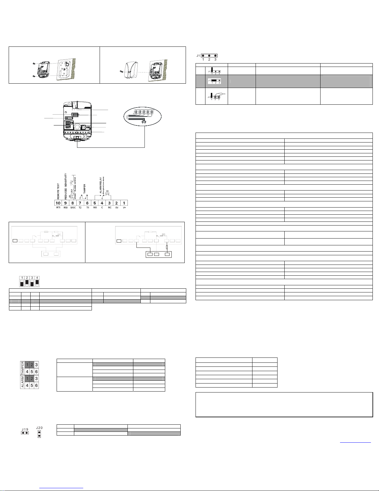
4.2.4 J1 Remote Test Settings
13. Attach the detector base on Mounting Plate SC110 and
then use the two M4×8mm screws provided to fix it.
14. Wire and configure the detector (see “4. Wirings and
Settings”), and then use the top screw to fix the
detector cover properly.
Position Function Method Result
1
No test Connect jumper to J1 pin 1 only.
1-2
Electronics test
Connect jumper to J1 pin 1 and 2;
Apply 0 volt to terminal 10 on the terminal
block (see Figure 6) to start the test.
A successful remote test will be
acknowledged by an alarm from
the detector within 1 second.
2-3
Complete test
including mounting
check
Connect Test Transmitter SC113 to J1 (black
cable to pin 2 and red cable to pin 3);
Apply 0 volt to terminal 10 on the terminal
block (see Figure 6) to start the test.
A successful remote test
including mounting check will be
acknowledged by an alarm from
the detector within 1 second.
4. Wirings and Settings
Wirings and settings are configured on detector base. All function modules on the d etector base are shown as below.
Figure 5 Detector Base
* Factory default settings are shown in grey.
J1
5. Maintenance
DIP Switches
Noise LED
Check the detector mounting and functions regularly (once a year at least).
Tamper Switch
Note: Connect T
erminal9 to low level (<0.6VDC), the sensitivity of detector will be reduced to about 1/8 of original level.
J19
EOL Jumpers
J20
6. Technical Specifications
Terminal Block
Power Requirements
Supply Voltage 8 ~ 16 VDC, nominal 12 VDC
Current Consumption (quiescent) Typical 3 mA @ 12 VDC
Current Consumption (alarm) Typical 2 mA @ 12 VDC
Voltage Ripple 100Hz, ≤10% of nominal voltage
Step Change Unom +/- 25%
Slow Change of Supply Voltage Unom +/- 25%
Warm-up Time < 5 sec
Sensitivity
Adjustable Sensitivity 4 levels by DIP Switches
Reduced Sensitivity (Maintenance, Service) Input Active low (terminal 9) ≤ 0.6 VDC
Detection Radius (Thermal Tools) on Concrete K350 5 m
Detection Radius (Thermal Tools) on Steel 5 m
Alarm Outputs
Solid State Relay SPDT (Change Over) 30 VDC / 100 mA / typical Ri=25 Ω
Transistor Open Collector Active low during alarm / Ri=1.38 kΩ
Alarm Hold Time Approx. 2.5 sec
Sabotage Protection
Pry-off and Cover S witch 30 VDC / 100 mA
Low Supply Voltage Alarm * < 6.5 VDC
Temperature Alarm * +85°C ± 5°C
Internal Functional Alarm* Stainless steel drill shield
* Sabotage and fault functions will cause the alarm relay to drop.
Inputs
Remote test of detector mounting and detector function or
Remote test of detector electronics only.
Active low ≤ 0.6 VDC, test duration < 1 sec
Reduced Sensitivity (maintenance, service) Input
Active low ≤ 0.6 VDC, duration = as long as active low
Sensitivity reduction to 12.5 %
Installation Tool
A noise and alarm indicator is incorporated to support sensitivity setting.
Environmental Conditions
Maximum Humidity 95% RH (non-condensing)
Operation Temperature -40°C ~ +70°C
Storage Temperature -50°C ~ +70°C
Environmental Class (VdS) III
Housing Protection Category IP43 IK04
Housing
Dimensions (H x W x D) 80 mm x 60 mm x 21 mm
Chassis and Cover Die-cast metal
Color RAL7035 (light grey)
Weight 0.228kg
4.1 Wirings
4.1.1 Terminal Block Wiring
The wirings should be connected to the terminal block first, and then should be conn ected to the panel.
Figure 6 Terminal Block Wiring
Note: The open collector alarm output
(terminal 8) will be active low during alarm.
4.1.2 Panel Wiring
According to the different terminal block wirings, there are two ways to connect the detector to the panel.
Alarm and tamper configured to one loop Alarm and tamper configured to two loops
RTI RSI S/OC T2 T1 C NC V+NO 0V
Z1
COM
Tamper
RT
Alarm
J20
RA
Connected to a zone configured as Dual-End-of-Line
RTI RSI S/OC T2 T1 C NC V+NO 0V
Tam pe r
RT
Alarm
J20
Z1
COM
Z2
Connected to a zone configured as Single-End-of-Line
Detec
tor
Detector
Note: W
hen this wiring
diagram is used, RT still
can be used for tamper
loop, but the jumper on
RA needs be removed
and the external EOL
resistor has to be
connected to alarm
loop.
External EOL
Resistor
Pan
el
Panel
4.2 Settings
4.2.1 DIP Switch Settings
ON
OFF
Sensitivity Settings Application Settings Noise LED
1 2 3 4
G
high
off off High sensitivity setting off ATMs/ Night deposit safes off Noise indicator OFF
G
normal
on off Normal sensitivity setting on Safes / Vaults on Noise indicator ON
G
low
off on Low sensitivity setting
G
noisy
on on Noisy environment sensitivity setting
7. Certifications and Approvals 8. Ordering Information
SC100 Seismic Vibration Detector meets approvals as
below:
NF&A2P Type 3
IMQ Type 3 (Pending)
UL (Pending)
ULC (Pending)
CE
CCC
VdS G 110004 class C
Mounting Plate
Movable Mounting Kit
Keyhole Protection Kit
Test Transmitter
1.8m Armored Cable Kit (8 wires)
External Test Transmitter
Recess Mounting Box
Floor Mounting Box
Spacer for Keyhole Protection Kit
SC110
SC111
SC112
SC113
SC114
SC115
SC116
SC117
SC118
* Factory default settings are shown in gre y.
Notes:
1. Any change of DIP switch 3 will cause an alarm.
2. Any change of DIP switch 3 must be followed by a power-off sequence of 5 seconds.
3. The Noise LED will light or flash intensively if the noise level (external or internal) is too high. Reduce the sensitivity with DIP switch
1 and 2 until the Noise LED turns off.
4. When scratching the surface of the protected object lightly, the Noise LED will turn on as a conf irmation of detection.
5. In case of alarm, the Noise LED will flash with 5 Hz, appx. 2.5 seconds.
6. Turning off the Noise LED by DIP switch 4 will reduce current consumption.
9. Shipping List
4.2.2 EOL Jumper Settings
Description Quantity
SC100 Seismic Vibration Detector 1
Screw M4x8mm 2
Cable Strap 1
Drill Plan 1
Two-way Jumper Link 1
Installation Guide 1
Jumper Position EOL Value
1-2 1K
2-3 2.2K
4-5 4.7K
TAMPER
(RT)
5-6 5.6K
1-2 1K
2-3 2.2K
4-5 4.7K
ALARM
(RA)
5-6 5.6K
* Factory default settings are shown in gre y.
Notice for Installation Guide
Pictures in the manual are for reference only. Please see the actual items.
The products will be updated and the information shall not be distributed.
Please read the book before operation and keep it properly for future use.
The manual has been reviewed and the accuracy is guaranteed. If there is any uncertainty or controversy, please refer to the final explanation of
Honeywell. Honeywell does not take any responsibility for any consequences caused by misunderstanding of the manual or improper operations.
Notes:
1. Refer to Control Panel manual for proper EOL selection.
2. For each block, only one EOL value can be set.
3. Other EOL resistor values can be used by removing all jumpers on the EOL jumper field and wire new resistors directly on the
terminal block.
4.2.3 J19/J20 Settings
No Jumper Jumper
J19 Terminal 8 = Not Used Terminal 8 = Alarm O/C Output
J20 Connect SC111/SC112 to the loop Normal Close
Honeywell
* Factory default settings are shown in grey.
© 2010 Honeywell International Inc.
www.honeywell.com/security
Document 800-04805 Rev. C
 Loading...