

Guide to Operation
Satellite XT R Version
Including Options:
Extractive Module XT
Pyrolyzer Module XT

Satellite XT R Version
toc-1
Table of Contents
Section 1 Basic Operation Page
1.1.............. Principle of Operation .................................................................................1-1
1.2............... Operating States ....................................................................................... 1-1
1.2.1 ............ Monitoring Mode ........................................................................................ 1-1
1.2.2 ............ Maintenance Mode ..................................................................................... 1-2
1.2.3 ............ Warning Condition ...................................................................................... 1-2
1.2.4 ............ Diagnostics ................................................................................................. 1-2
1.3............... Menu structure............................................................................................ 1-2
1.3.1 ............ Maintenance Menu ..................................................................................... 1-2
1.3.2 ............ Calibration Menu......................................................................................... 1-2
1.3.3 ............ Conguration Menu .................................................................................... 1-2
1.4............... Operational Elements ................................................................................. 1-3
1.4.1 ............ Keypad Functions....................................................................................... 1-3
1.4.2 ............ Graphic Display .......................................................................................... 1-3
1.5............... Technical Specications ............................................................................. 1-4
Section 2 Installation and Start-up
2.1............... General Guidelines..................................................................................... 2-1
2.2............... Standard Mounting ..................................................................................... 2-1
2.3............... Duct Mounting............................................................................................. 2-3
2.3.1 ............ Connecting the Sensor Extension to the Instrument .................................. 2-3
2.3.2 ............ Mounting the Sensor Extension to the Duct ............................................... 2-4
2.4............... Wiring.......................................................................................................... 2-5
2.5............... Initial Start-Up ............................................................................................. 2-7
Section 3 Main Menu
3.1............... The Main Menu Screens............................................................................. 3-1
3.2............... Main Menu - Monitoring.............................................................................. 3-2
3.3............... Main Menu - Maintenance .......................................................................... 3-3
3.4............... Main Menu - Calibration.............................................................................. 3-4
3.5............... Main Menu - Conguration ......................................................................... 3-5
Section 4 Mantenimiento
4.1............... Sensor Service ........................................................................................... 4-3
4.2............... Alarm Reset................................................................................................ 4-4
4.3............... Alarm/Warn Test......................................................................................... 4-4
4.4............... Device Infos ................................................................................................ 4-5
4.5............... Sensor Infos................................................................................................ 4-6
4.6............... Reset Device .............................................................................................. 4-8
4.7............... Service........................................................................................................ 4-8
Section 5 Calibration
5.1.............. Gas Calibration ........................................................................................... 5-2
5.1.1 ............ Zero Adjust ................................................................................................. 5-2
5.1.2 ............ Span Adjust ................................................................................................ 5-3
5.2............... Manual K-Factor ......................................................................................... 5-4

Satellite XT R Version
Section 6 Conguration Page
6.1............... Alarm Settings ............................................................................................6-3
6.1.1 ............ Alarm 1 .......................................................................................................6-4
6.1.2 ............ Alarm 2 .......................................................................................................6-7
6.2............... Language....................................................................................................6-8
6.3............... Date Format................................................................................................6-8
6.4............... Auto Selftest .............................................................................................. 6-9
6.5............... Security........................................................................................................6-9
6.6............... Password................................................................................................... 6-10
6.7............... Location ..................................................................................................... 6-10
6.8............... New Sensor Type ...................................................................................... 6-11
6.9............... Gas Name.................................................................................................. 6-11
6.10............. Relays........................................................................................................ 6-12
Section 7 Troubleshooting
7.1............... Warning and Fault Messages...................................................................... 7-1
7.1.1 ............ Warnings......................................................................................................7-1
7.1.2 ............ Faults ..........................................................................................................7-2
Section 8 Reference Information
8.1............... Sensor Order Information ........................................................................... 8-1
8.2............... Spares and Accessories............................................................................. 8-3
Section 9 Extractive Module XT - Option
9.1............... Principle of Operation ................................................................................. 9-1
9.2............... General Instructions.................................................................................... 9-1
9.3............... Safety Instructions ...................................................................................... 9-1
9.4............... Instrument Design....................................................................................... 9-2
9.5............... Mounting..................................................................................................... 9-4
9.6............... Tubing Connections.................................................................................... 9-4
9.7............... Sensor Replacement .................................................................................. 9-5
9.8............... Technical Specications ............................................................................. 9-6
Section 10 Pyrolyzer Module XT - Option
10.1............. Principle of Operation ............................................................................... 10-1
10.2............. General Instructions................................................................................... 10-1
10.3............. Safety Instructions ..................................................................................... 10-1
10.4............. Instrument Design...................................................................................... 10-2
10.5............. Mounting.................................................................................................... 10-3
10.6............. Tubing Connections................................................................................... 10-4
10.7............. Data Link.................................................................................................... 10-4
10.8............. Power Connection ..................................................................................... 10-4
10.9............. Technical specications............................................................................. 10-5
Table of Contents
toc-2

Satellite XT R Version
This section provides a basic understanding of the instrument and its operation.
1.1 Principle of Operation
The Satellite XT R Version is a generic gas monitoring instrument for the detection of a wide
range of hazardous gases. Power is supplied by a local 12 to 24 VDC power supply.
Target gas and measuring range depend on the type of sensor chosen. The sensor comes with
the specic data in its internal data memory.
The Satellite XT R Version provides 3 single-pole single-throw relays for activation of external
alarm devices. If the gas concentration exceeds the alarm levels, the instrument will activate
the appropriate alarm relay and display an according message. A relay will also be activated in
case of an instrument fault.
1.2 Operating States
There are four different operating states for the Satellite XT, Monitoring Mode, Maintenance
Mode, Warning Condition, and Diagnostics. Depending on the selected operating state, the
green status LED is either on, off, or ashing.
1.2.1 Monitoring Mode
The Monitoring Mode is the instrument’s standard operating mode. In the Monitoring Mode,
the instrument continuously monitors for hazardous gas concentrations and checks for alarm
levels and instrument faults.
The instrument’s self-diagnostics provides on-line preventive maintenance information
identifying electronics or sensor problems, e.g. a sensor selftest is performed every 24 hours.
The green LED located above the <set> key is on.
The settings for Alarm Level 1 and Alarm Level 2 are automatically loaded when installing the
sensor. Standard settings are 1x and 2x TLV (Threshold Limit Value) for the target gas. The
Alarm Setup function in the Conguration Menu allows the user to change the alarm levels
according to their specic requirements.
Whenever the concentration of the target gas exceeds the factory or user programmed alarm
levels, the instrument will document this concentration alarm condition on its LCD Display and
trigger the associated alarm relays.
1.2.1.1 Reset Alarms Function
Ex factory, Alarm 1 and Alarm 2 are preprogrammed “enabled” and “latching”. In the event of a
concentration alarm, the alarm indication with latching alarms will continue until the alarm is
manually acknowledged by pressing the <set> key. Alarm Reset is not possible, if the alarm
condition is still present.
1.2.1.2 Exiting the Monitoring Mode
Exiting the Monitoring Mode and entering the Maintenance Mode may be password protected.
To prevent the instrument from manipulations by unauthorized personnel, it is recommended to
enable this function (see Conguration Menu / Security Function).
- Password enabled:
Press the <esc> key to exit the Monitoring Mode and enter the password. The screen to enter
the password is shown for one minute. During this period the Monitoring Mode remains active
in the background. When the correct password has been entered, the instrument is in the
Maintenance Mode, it is not monitoring, and the green LED is off.
- Password disabled:
Press the <esc> key to exit the Monitoring Mode. The instrument is now in the Maintenance
Mode, the instrument is not monitoring, and the green LED is off.
Basic Operation - Section 1
1-1

Satellite XT R Version
1.2.2 Maintenance Mode
The Maintenance Mode indicates a complete absence of monitoring capability. The green status
LED is off. Depending on the conguration the fault relay will be activated.
1.2.3 Warning Condition
A warning condition indicates that the instrument requires some attention, but the instrument is still
able to monitor and operate as programmed.
The following will occur when the instrument detects a warning condition:
- the green status LED is ashing
- depending on the conguration the fault relay will be activated.
1.2.3.1 Reset Warning Condition
Press the <set> key to acknowledge and reset a Warning Condition.
Refer to Section 7, Troubleshooting for specic warnings.
1.2.4 Diagnostics
Instrument faults refer to a problem which prevents the instrument from operating properly and
interferes with the ability to monitor or document concentration alarms.
If the instrument has detected an instrument fault, the fault relay is activated. The green status LED
is off. The LCD display is ashing while indicating the specic fault message.
The instrument lists specic instrument responses to instrument faults. For information on the
various fault messages and instructions on how to correct a fault condition, please refer to
Section 7, Troubleshooting.
1.3 Menu structure
Besides the Monitoring Mode, there is also menu operation for the Satellite XT. Menu operation
comprises three groups of functions, maintenance, calibration, and conguration. A password
(if enabled) must be entered to exit the Monitoring Mode and to obtain access to the Main Menu.
1.3.1 Maintenance Menu
This function covers the realtime service procedures required for a regular maintenance of the
instrument (e.g. sensor replacement).
1.3.2 Calibration Menu
Use the calibration function to dynamically calibrate the instrument with a known concentration of
the target gas or manually by entering a new correction K-Factor.
1.3.3 Conguration Menu
Use this function to congure the Satellite XT and to program instrument and monitoring
parameters to suit individual requirements.
! Note:
If the instrument was in the Monitoring Mode when last powered down,
it will automatically return to the Monitoring Mode when power is restored.
1-2
Basic Operation - Section 1
Satellite XT R Version
1-3
1.4 Operational Elements
Located at the front of the instrument is the
graphic display, the keypad consisting of six
keys, and above the Set Key the green status
LED.
1.4.1 Keypad Functions
o Escape Key <esc>
o Set Key <set>
o 4 Cursor Keys marked with an arrow,
<up>, <down>, <left>, <right>.
In the Maintenance, Calibration, and Conguration Menu, these keys provide the following functions:
To move forwards and backwards in the menus, use the cursor keys <down> and <up>. Select a
function by pressing the <set> key.
To enter text or gures, use the cursor keys <left> and <right> to reach the desired cursor position.
Use the cursor keys <up> and <down> to select the letter, gure, or sign you wish to enter. Bring the
cursor to the next position, select the next letter, gure, or sign. After entering the complete text, use
the <set> key to conrm the changes. If you do not want to save the changes, abort by pressing the
<esc> key.
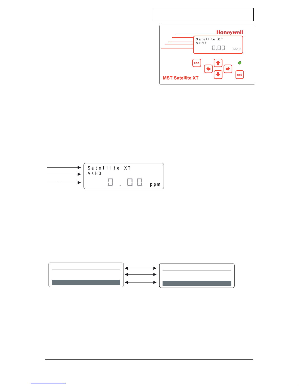
1.4.2 Graphic Display
Depending on the operating mode the structure of the graphic display is different. Three
basic versions are illustrated and explained below. A detailed description is given in the
according sections.
Display Structure for Monitoring Mode
Line 1 offers the possibility to enter a user specic description, e.g. monitoring location
(max. 13 spaces; the name of the instrument is entered here when delivered).
Line 2 shows the name of the gas monitored.
Line 3 indicates the actual gas concentration and the concentration unit. Gas name and
concentration unit are data stored in the memory of the sensor installed.
Display Structure for Menu
Line 1 shows the actual position in the menu. In the left example the actual position is
Main Menu, in the right example it is the Sub-Menu Maintenance.
Line 2 shows one of the selection possibilities.
Line 3 shows the number of the selection possibility presently displayed and indicates also
the total of selection possibilities available in this menu.
M E N U
M A I N T E N A N C E
S E N S O R S E R V I C E
Línea 1
Línea 2
Línea 3
s ele c t : 2 o f 4
s ele c t : 1 o f 7
M A I N T E N A N C E
Basic Operation - Section 1
Line 1
Line 2
Line 3
Line 1
Line 2
Line 3

Satellite XT R Version
1.5 Technical Specications
Power Requirements
voltage 12 - 24 VDC (18 VDC minimum when using the Extractive Module)
consumption Max. 1.4 W
Wiring
power
2-wire shielded cable 2x0.5 mm2 / 20.4 AWG
(approx. 2 m delivered with instrument)
relay contacts
6-wire shielded cable 6x0.25 mm2 / 23 AWG
(approx. 3 m delivered with instrument)
Relay Outputs
contacts 3 x SPST (single-pole single-throw)
max. ratings 250 VAC / 30 VDC, 2 A
Graphic Display 122 x 32 dots with backlight
Status LED Green
Keypad 6 touch-sensitive membrane function keys
Physical Dimensions
size
145 x 95 x 50 mm (L x W x H)
5.7” x 3.7” x 2.0” (L x W x H)
weight
620 grams
22 ounces
Mounting
special mounting plate
(delivered with instrument)
Housing Protection Class IP 52 option: IP 65
EMC Directive 2004/108/EC
EN 50270
Operating Conditions
temperature
-20 °C ... +40 °C
-4 °F ... +104 °F
pressure 700 ... 1300 hPa
humidity 20 ... 90 % r.h.
Part Number
Satellite XT R 9602-0505
Satellite XT R, IP 65 9612-0505
1-4
Basic Operation - Section 1
Satellite XT R Version
2-1
Installation and Start-Up - Section 2
This section explains installation and initial start-up procedures.
2.1 General Guidelines
Please consider the aspects indicated below before locating the instrument.
The property of the target gas (lighter or heavier than air) must be considered. The
instrument should be mounted as close to the monitoring location as possible and should
be easily accessible for operation and maintenance. For narrow monitoring locations or
duct mounting a sensor extension with a standard length of 2m (6 feet) is available as an
option.
The optimum position to mount the instrument is in an upright position on a at surface.
If the instrument is used for ambient air monitoring, ensure that the sensor is facing
downwards. For personal monitoring applications the instrument should be mounted at
head level.
Ensure that the area immediately surrounding the instrument is free from objects that
might hinder free ow of air. The instrument should be installed away from any possible
liquid sources, extreme dust and dirt sources and should be protected against rain and
sunlight. An instrument version protection class IP 65 is available for outdoor applications.
A junction box is recommended to connect the instrument to external control systems.
A distance of 2 m (6 feet) must not be exceeded.
Regarding the power requirements and operating conditions, please follow the
specications indicated in Section 1, Technical Specications, for wiring instructions refer
to Section 2, Wiring.
The sensors should be stored in a cool, dry place when not in use.
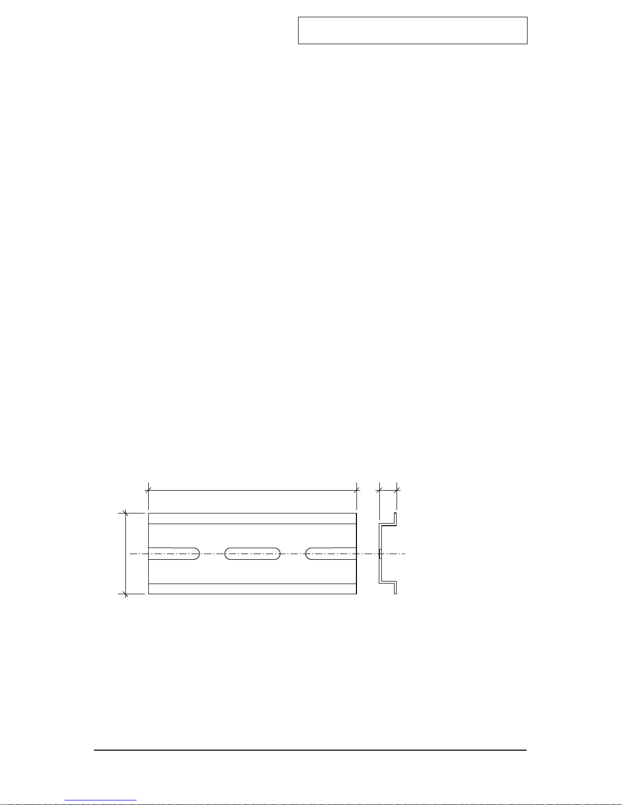
2.2 Standard Mounting
The instrument is designed for DIN–rail mounting. The mounting rail standard shipped with
each instrument is used for wall mounting. Mount the DIN–rail to a wall and fasten the
instrument with the sensor downwards and the display facing the front.
Attach the wires to the junction box according to the wiring diagram provided in the course
of this section.
Installation and Start-Up - Section 2
This section explains installation and initial start-up procedures.
Please consider the aspects indicated below before locating the instrument.
The property of the target gas (lighter or heavier than air) must be considered.
The instrument should be mounted as close to the monitoring location as possible and should be easily
accessible for operation and maintenance. For narrow monitoring locations or duct mounting a sensor
extension with a standard length of 2m (6 feet) is available as an option.
The optimum position to mount the instrument is in an upright position on a flat surface. If the instrument
is used for ambient air monitoring, ensure that the sensor is facing downwards. For personal monitoring
applications the instrument should be mounted at head level.
Ensure that the area immediately surrounding the instrument is free from objects that might hinder free
flow of air. The instrument should be installed away from any possible liquid sources, extreme dust and
dirt sources and should be protected against rain and sunlight. An instrument version protection class
IP 65 is available for outdoor applications.
A junction box is recommended to connect the instrument to external control systems. A distance of 2 m
(6 feet) must not be exceeded.
Regarding the power requirements and operating conditions, please follow the specifications indicated in
Section 1, Technical Specifications, for wiring instructions refer to Section 2, Wiring.
The sensors should be stored in a cool, dry place when not in use.
The instrument is designed for DIN–rail mounting. The mounting rail standard shipped with each
instrument is used for wall mounting. Mount the DIN–rail to a wall and fasten the instrument with the
sensor downwards and the display facing the front.
Attach the wires to the junction box according to the wiring diagram provided in the course of this
section.
90,0
35,0
7,5
Mounting rail standard (P/N 9602.0050.10.03)
Satellite XT R Version
2-2
Installation and Start-Up - Section 2
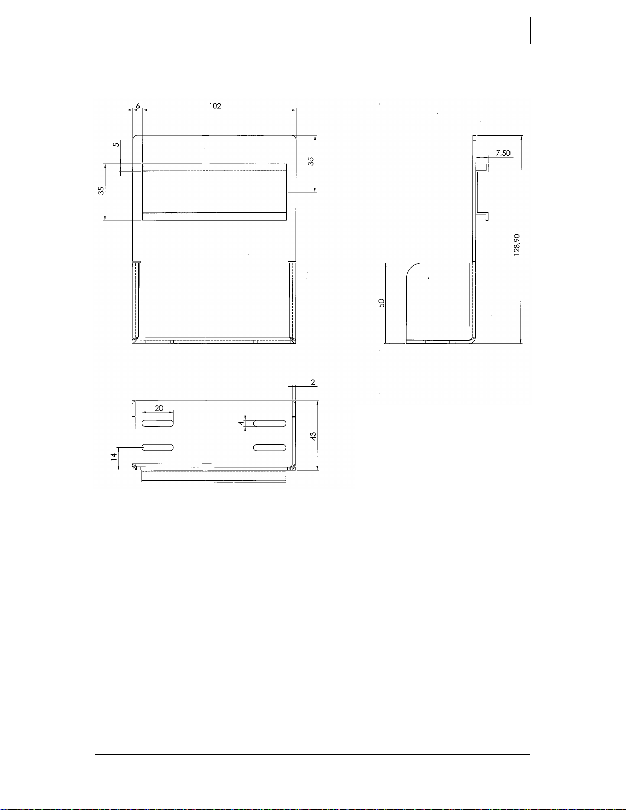
For applications where wall mounting is not possible, an L-shaped mounting plate with DIN–rail is
available as an option.
Optional L-shaped mounting plate with DIN–rail (P/N 9602.0051.10.02)
! Note:
Do not apply power until system is ready for start-up!

Satellite XT R Version
2-3
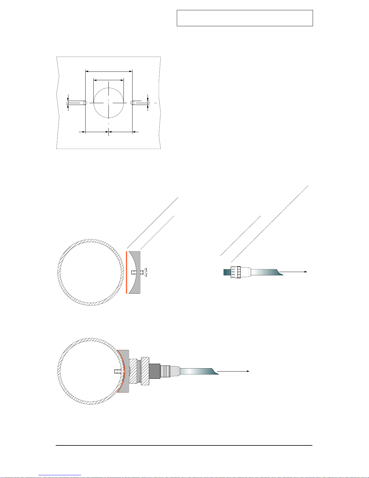
2.3 Duct Mounting
Observe the guidelines for installation of the instrument. For assembly and installation of
the sensor extension see the schematics below and overleaf.
2.3.1 Connecting the Sensor Extension to the Instrument
1. Connect the Socket (A) to the plug in the sensor compartment located at the bottom of
the Satellite XT. The groove of the Socket must face to the front.
2. Screw in the Internal Cap (B) and fasten it hand-tight.
3. Insert the Sensor Housing (C) with the nose of the Bayonet Catch facing to the front.
Lock the Bayonet Catch with a quarter-turn right.
1
2
3
A
B
C
D
A Socket with Groove
B Internal Cap
C Sensor Housing with Bayonet Catch
D Extension Cable to the Sensor
Installation and Start-Up - Section 2
Satellite XT R Version
2-4
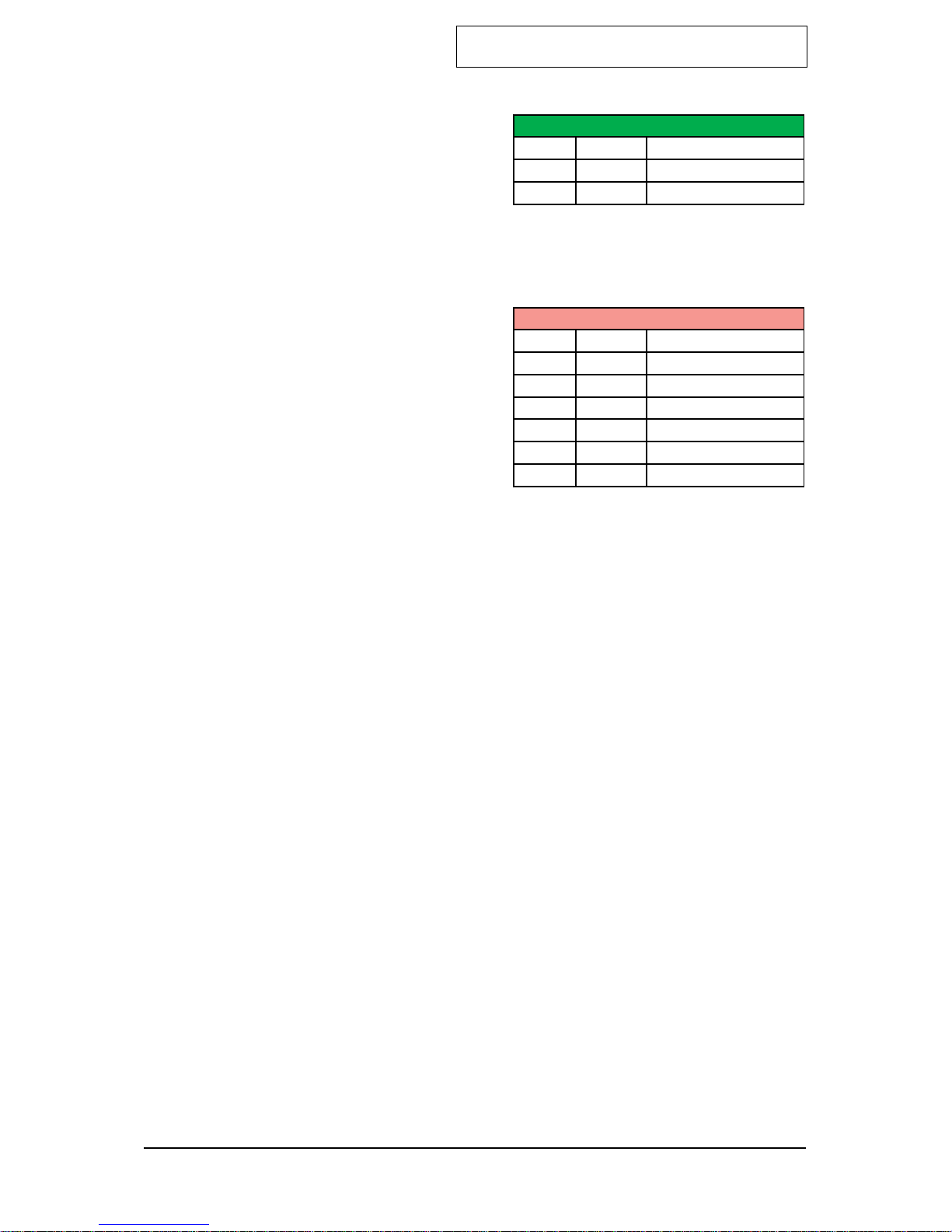
2.3.2 Mounting the Sensor Extension to the Duct
Duct
*) Duct Mounting Saddle Assembly various types
available, see spare parts list, Section 8,
Reference Information
5,2cm
3,3cm
2,6cm 2,6cm
0,4cm
0,4cm
Duct
Satellite XT
Duct
Duct Mounting Saddle *)
9902.0080.40.00 Silicon Sealing
Sensor Extension
9902.0004.40.01 Milled Nut
Sensor
Satellite XT
Installation and Start-Up - Section 2
Satellite XT R Version
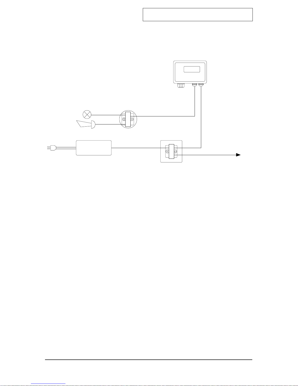
2.4 Wiring
There are two permanently attached cables extending
from the bottom of the instrument, a 2-wire shielded
cable with a length of 2 meters and a 6wire shielded cable with a length of 3 meters.
The 2-wire shielded cable is required to power the
instrument. The open end of the cable should be
terminated in a junction box.
The 6-wire shielded cable provides a pair of
connections for each of the 3 internal relays for
activation of visual or audible external alarm devices.
Power Supply Connections
P+ White Power +
P– Brown Power -
S Shield cable shield
Relay Contacts
1 White Alarm 1 Relay
1 Brown Alarm 1 Relay
2 Green Alarm 2 Relay
2 Yellow Alarm 2 Relay
3 Grey Fault Relay
3 Pink Fault Relay
S Shield Cable shield
Note:
All wiring for the Satellite XT and its related equipment must be in compliance with any local
electrical and re codes. The Satellite XT wiring must be kept away from any high power lines.
All shielding for the wiring must be connected together and grounded at only one point in the
system.
2-5
Installation and Start-Up - Section 2
Satellite XT R Version
2-wire shielded cable
2-wire shielded cable
2 m provided with instrument
230 / 115 VAC
2-wire shielded cable
to additional control devices
Junction Box
Satellite XT R
6-wire shielded cable
3 m provided with instrument
Junction Box
Power Supply
24 VDC
2-6
Wiring Diagram Satellite XT R - Basic Conguration
Installation and Start-Up - Section 2
Satellite XT R Version
2-7
2.5 Initial Start-Up
When wiring is completed, a sensor must be assigned to each instrument. Every sensor is
gas calibrated and these sensor specic calibration parameters are stored in its integrated
data memory. Make sure to use only sensors designed for use with the Satellite XT.
Ex factory the instruments are shipped either uncongured or already precongured
according to the customer’s specications.
If the instruments are precongured, a certain sensor, which can be identied by its serial
number printed on the packaging and the sensor label, is assigned and documented to
one particular instrument. These data are stated in the test certicate provided with the
shipment.
Switch on power supply. If no sensor is tted, the display of the instrument shows the
below message.
---- F A U L T ----
N O S E N S O R !
For applications without sensor extension open the bayonet catch of the sensor housing
located on bottom of the instrument with a quarter-turn left and remove the sensor housing.
For applications with sensor extension hold the plastic tting at the duct side with two ngers
and unscrew the metal tting.
Take the assigned sensor out of the packaging. Remove shorting strap or wire link placed in
the sensor plug before inserting it into the instrument. Not all sensors will feature this strap or
link.
Caution: Failure to remove the shorting strap or wire link may result in damage to
the Satellite.
For applications without sensor extension insert the sensor into the instrument’s sensor
compartment with the arrow printed on the sensor label facing upwards and to the front. Fit
sensor housing by fastening the bayonet catch with a quarter-turn right.
For applications with sensor extension insert the sensor into the socket inside the metal
tting, properly aligning notch, groove, and arrow printed on the sensor label.
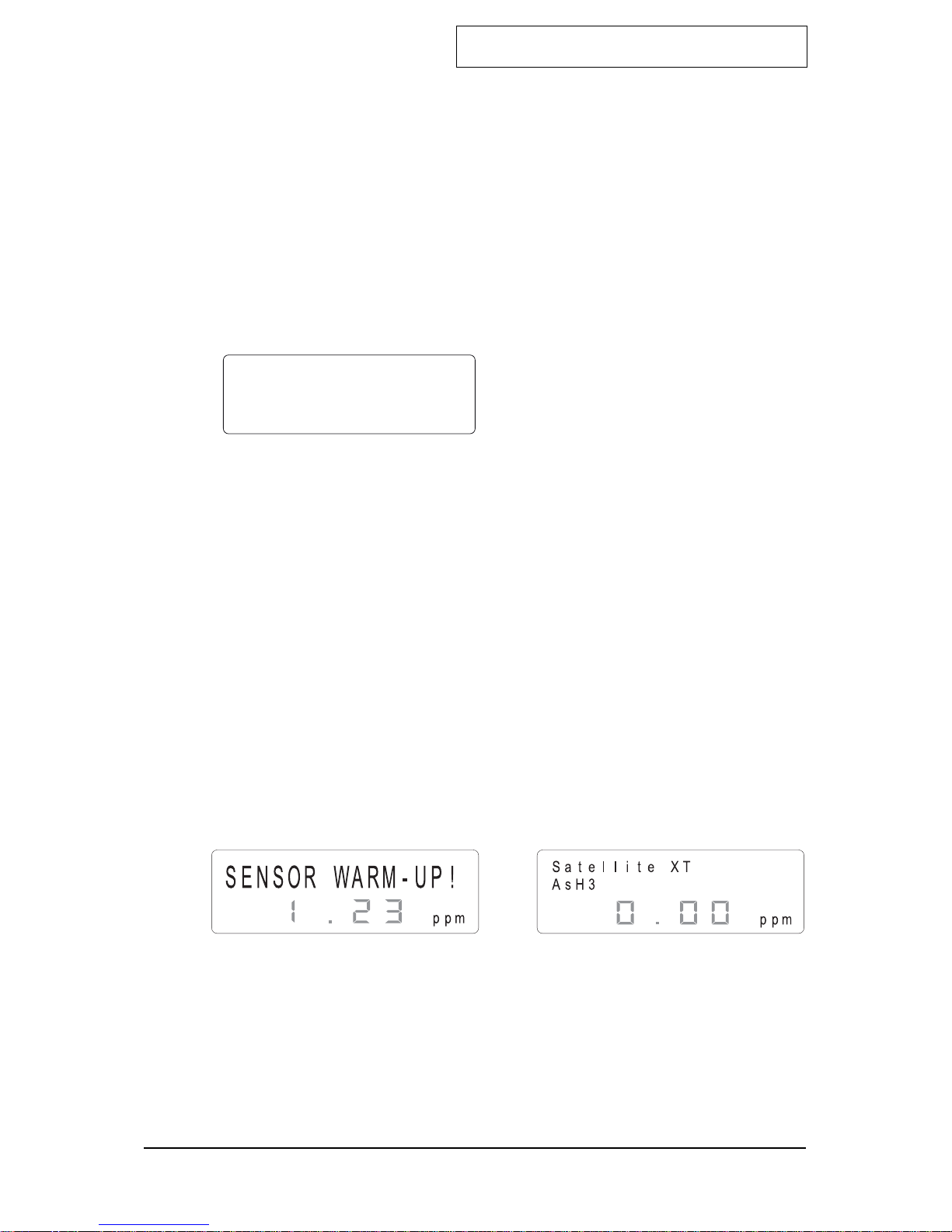
A sensor warm-up is performed and the graphic display shows the according screen until the
displayed value is zero.
This does not apply for oxygen sensors. The warm-up time required depends on the type of
sensor installed. The instrument is in the Maintenance Mode and the green LED is off.
As soon as the displayed value reads zero, the instrument automatically switches to the
Monitoring Mode. The graphic display shows the according screen, the green status LED
is on, the instrument is monitoring.
! Note:
If the instrument does not perform as described above and a fault message is
shown, please refer to Section 7, Troubleshooting.
! Instruments with OXYGEN sensors:
Span Adjustment must be performed prior to start-up. It is recommended to repeat
Span Adjustment every 4 to 6 weeks. For details refer to Section 5, Calibration.
Installation and Start-Up - Section 2

Satellite XT R Version
2-8
Installation and Start-Up - Section 2
Satellite XT R Version
3-1
Main Menu - Section 3
This section explains the different monitoring conditions and the Sub-Menus available
under the Main Menu.
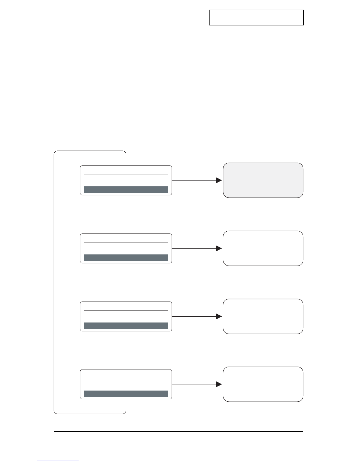
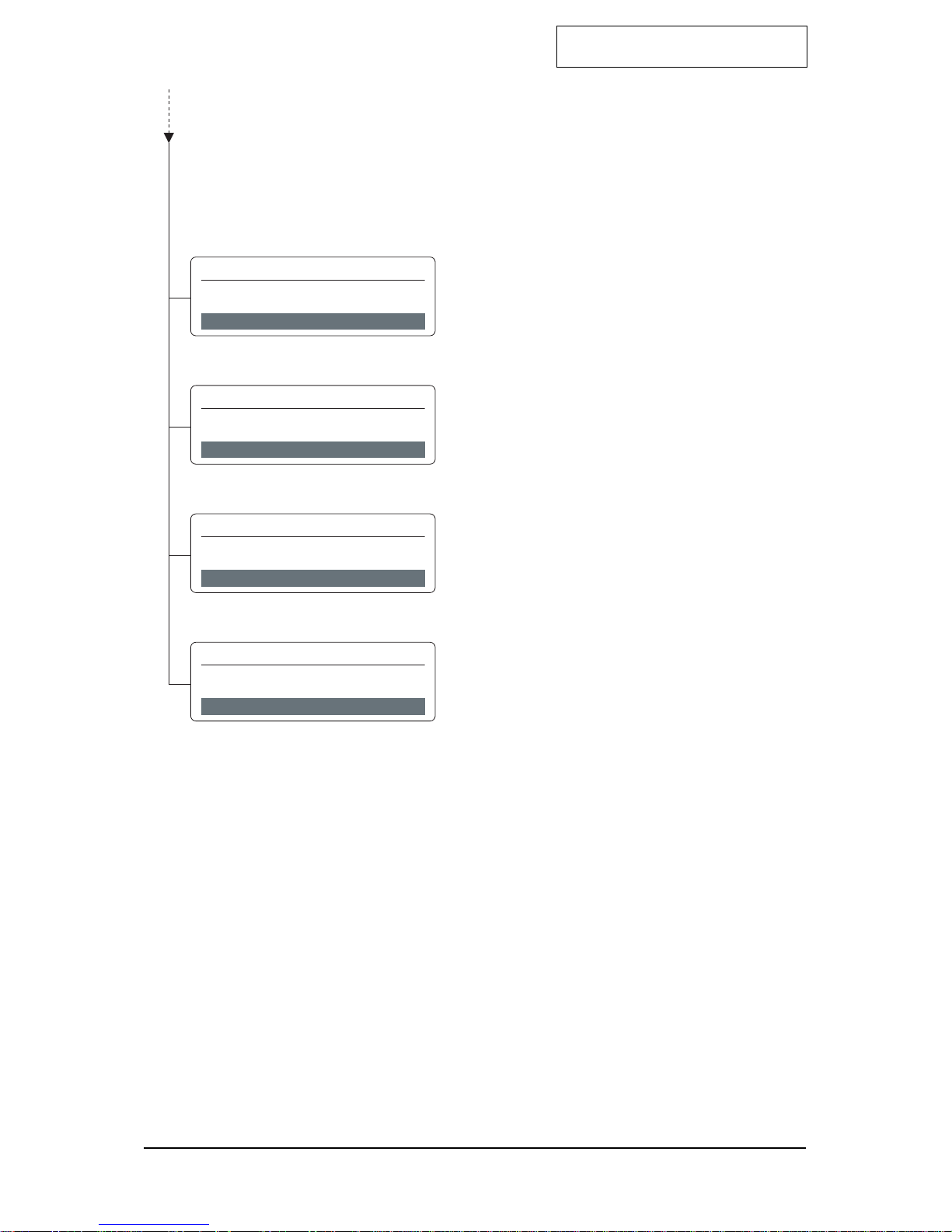
3.1 The Main Menu Screens
When the <esc> key is pressed, the instrument will leave the Monitoring Mode and go
to the Main Menu. The instrument is now in the Maintenance Mode and the green LED
is off.
Press the cursor keys <up> or <down> to move forwards and backwards in the Main
Menu.
Press the <set> key to select a Sub-Menu. Press the <esc> key to go back to the Main
Menu.
To return to the Monitoring Mode, go to the menu ‘MONITORING’ and press <set> to
select. The display shows the monitoring screen again and the illuminated green LED
indicates, that the instrument is in the Monitoring Mode.
s ele c t : 1 o f 4
M O N I T O RIN G
M E N U
s ele c t : 2 o f 4
M A I N T E N A N C E
M E N U
s ele c t : 3 o f 4
C A L I B R A T I O N
M E N U
s ele c t : 4 o f 4
CON F I G U R A T I O N
M E N U
Monitoring Mode
Sub-Menus
Sub-Menus
Sub-Menus
Satellite XT R Version
3-2
Main Menu - Section 3
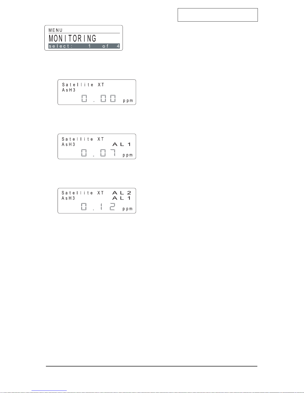
Main Menu - Monitoring
The instrument is in the operating mode
Maintenance and the green LED is off.
Press the cursor keys <up> or <down> to move
forwards and backwards in the Main Menu.
Press the <set> key to enter the Monitoring Mode.
<Normal Condition>
This screen and the illuminated green LED indicate
that the instrument is in the Monitoring Mode and is
operating properly.
<Alarm 1 Condition>
This screen shows that Alarm Level 1 has
been exceeded and that there is an actual gas
concentration of 0.07 ppm AsH3.
(f.i. Alarm 1 set at 0.05 ppm AsH3)
<Alarm 2 Condition>
This screen shows that Alarm Level 2 has been
exceeded and that there is an actual gas concentration
of 0.12 ppm AsH3.
(f.i. Alarm 2 set at 0.10 ppm AsH3)

Satellite XT R Version
s ele c t : 1 o f 7
M A I N T E N A N C E
S E N S ORS E R V I C E
s ele c t : 2 o f 7
M A I N T E N A N C E
A L A RM R ESE T
s ele c t : 4 o f 7
M A I N T E N A N C E
D E V I C E I N F O S
s ele c t : 5 o f 7
M A I N T E N A N C E
S E N S ORI N F O S
s ele c t : 6 o f 7
M A I N T E N A N C E
R ESE T D E V I C E
s ele c t : 7 o f 7
M A I N T E N A N C E
S E R V I C E
M A I N T E N A N C E
s ele c t : 2 o f 4
M E N U
s ele c t : 3 o f 7
M A I N T E N A N C E
A L A RM /WA R N T E S T
3-3
Main Menu - Section 3
Main Menu - Maintenance
The instrument is in the Maintenance Mode and the
green LED is off.
Press the cursor keys <up> or <down> to move
forwards and backwards in the Main Menu.
To select a Sub-Menu, press the <set> key to enter.
Sub-Menus - Maintenance
Sensor Service
screen 1 of 7
Alarm Reset
screen 2 of 7
Alarm/Warn Test
screen 3 of 7
Device Infos
screen 4 of 7
Sensor Infos
screen 5 of 7
Reset Device
screen 6 of 7
Service
screen 7 of 7
Satellite XT R Version
3-4
Main Menu - Section 3
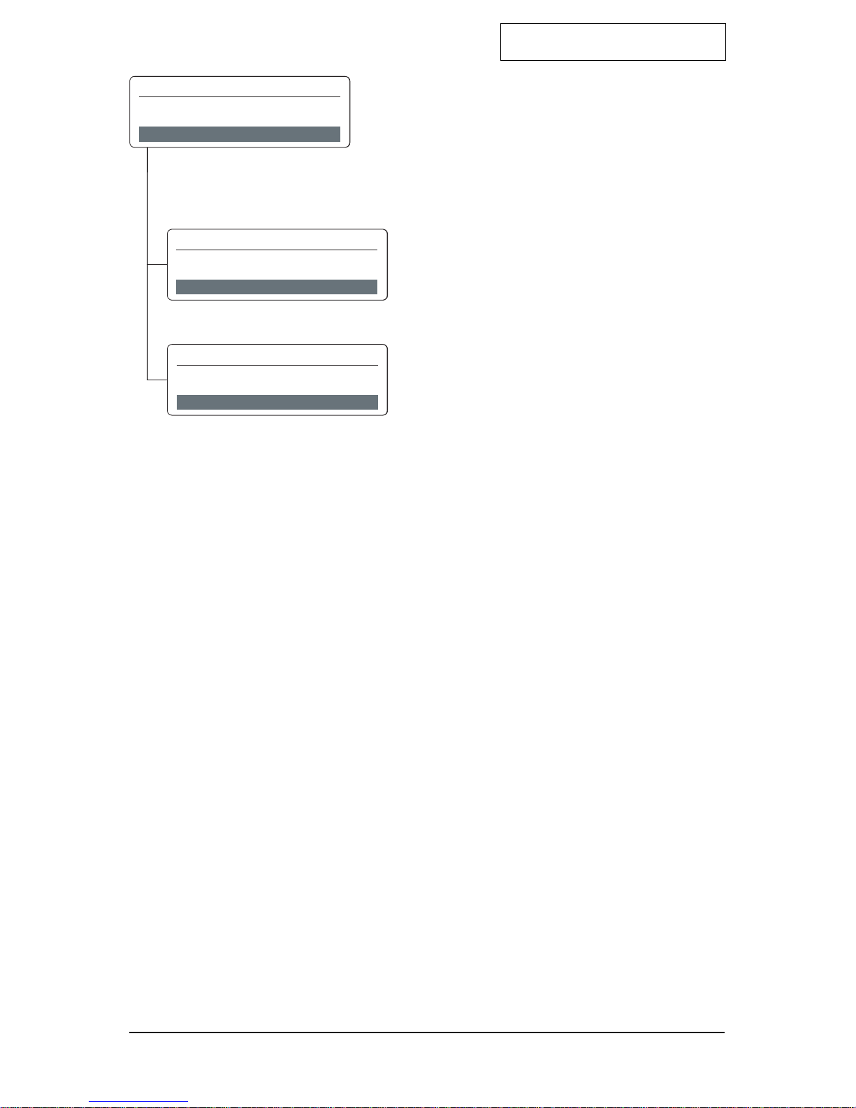
Main Menu - Calibration
The instrument is in the Maintenance Mode and
the green LED is off. Press the cursor keys <up> or
<down> to move forwards and backwards in the Main
Menu.
To select a Sub-Menu, press the <set> key to enter.
Sub menus - Calibration
Gas Calibration
screen 1 of 2
Manual K-Factor
screen 2 of 2
C A L I B R A T I O N
s ele c t : 3 o f 4
M E N U
s ele c t : 1 o f 2
C A L I B R A T I O N
G A S C A L I B R A T I O N
s ele c t : 2 o f 2
C A L I B R A T I O N
M A N U A L K - F A C T O R
C A L I B R A T I O N
s ele c t : 3 o f 4
M E N U
s ele c t : 1 o f 2
C A L I B R A T I O N
G A S C A L I B R A T I O N
s ele c t : 2 o f 2
C A L I B R A T I O N
M A N U A L K - F A C T O R
Satellite XT R Version
3-5
Main Menu - Section 3
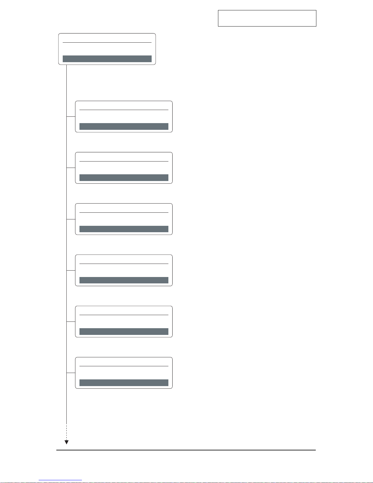
Main Menu - Conguration
The instrument is in the Maintenance Mode and the
green LED is off.
Press the cursor keys <up> or <down> to move
forwards and backwards in the Main Menu.
To select a Sub-Menu, press the <set> key to enter.
Sub Menus - Conguration
Alarm Settings
screen 1 of 10
Language
screen 2 of 10
Date Format
screen 3 of 10
Auto Selftest
screen 4 of 10
! This function is not available with instruments
using oxygen sensors.
Security
screen 5 of 10
Password
screen 6 of 10
s ele c t : 1 o f 1 0
CON F I G U R A T I O N
ALA R M S E T T I N G S
s ele c t : 2 o f 1 0
CON F I G U R A T I O N
L A NGU AGE
s ele c t : 3 o f 1 0
CON F I G U R A T I O N
D ATE F O R M A T
s ele c t : 4 o f 1 0
CON F I G U R A T I O N
A U T O S E L F T E S T
s ele c t : 5 o f 1 0
CON F I G U R A T I O N
S E CUR I T Y
s ele c t : 6 o f 1 0
CON F I G U R A T I O N
PASSWO R D
CON F I G U R A T I O N
s ele c t : 4 o f 4
M E N U
continued
Continued
Satellite XT R Version
3-6
Main Menu - Section 3
Main Menu - Conguration
Sub menus - Conguration
Location
screen 7 of 10
New Sensor Type
screen 8 of 10
Gas Name
screen 9 of 10
Relays
screen 10 of 10
s ele c t : 7 o f 1 0
CON F I G U R A T I O N
L O C A T I O N
continued
s ele c t : 8 o f 1 0
CON F I G U R A T I O N
N EWS E N S O R T YPE
s ele c t : 9 o f 1 0
CON F I G U R A T I O N
G A S N AME
s ele c t : 1 0 o f 1 0
CON F I G U R A T I O N
R E L AYS
Continued
 Loading...