

Page 1

Release 131
Safety Manager
Safety Manual
EP-SM.MAN.6283
Issue 4
10 July 2008
Page 2

Document Release Issue Date
EP-SM.MAN.6283 131 4 July 2008
Notice
This document contains Honeywell proprietary information. Information
contained herein is to be used solely for the purpose submitted, and no part of this
document or its contents shall be reproduced, published, or disclosed to a third
party without the express permission of Honeywell Safety Management Systems.
While this information is presented in good faith and believed to be accurate,
Honeywell disclaims the implied warranties of merchantability and fitness for a
purpose and makes no express warranties except as may be stated in its written
agreement with and for its customer.
In no event is Honeywell liable to anyone for any direct, special, or consequential
damages. The information and specifications in this document are subject to
change without notice.
Copyright 2008 – Honeywell Safety Management Systems, a division of
Honeywell Aerospace B.V.
Honeywell trademarks
Experion PKS
U.S. registered trademarks of Honeywell International Inc.
®
, PlantScape®, SafeBrowse®, TotalPlant® and TDC 3000® are
Conventions
ii
Other trademarks
Microsoft and SQL Server are either registered trademarks or trademarks of
Microsoft Corporation in the United States and/or other countries.
Trademarks that appear in this document are used only to the benefit of the
trademark owner, with no intention of trademark infringement.
Symbols
The following symbols are used in Safety Manager documentation:
Attention
This symbol is used for information that emphasizes or supplements important points of
the main text.
Page 3
Tip
This symbol is used for useful, but not essential, suggestions.
Note
This symbol is used to emphasize or supplement important points of the main text.
Caution
This symbol warns of potential damage, such as corruption of the database.
Warning
This symbol warns of potentially hazardous situations, which, if not avoided, could result
in serious injury or death.
ESD
This symbol warns for danger of an electro-static discharge to which equipment may be
sensitive.
iii
Page 4

Fonts
The following fonts are used in Safety Manager documentation:
Emphasis
• “... inform the reader on how to perform
the task in terms of...”
• “...see the Overview Guide”
Label
“The Advanced tab of the Properties
window has..”
Steps
Take the following steps:
1. Create a plant and set its properties.
2. ....
User Variable
..create the My Projects folder and
store the readme.txt file here.
..press the Tab key..
Next press Enter to..
Value
“Low is the fault reaction state for digital
inputs and digital outputs.”
Variable
“The syntax is: filename [-s] [-p]“
http://www.honeywellsms.com This font is used to identify a URL, directing
Emphasised text is used to:
• emphasise important words in the text,
• identify document titles.
This font is used to identify labels and titles
of (popup) windows.
Labels are used for Dialog box labels, menu
items, names of properties, and so on.
This font is used to identify steps.
Steps indicate the course of action that must
be adhered to, to achieve a certain goal.
This font is used to:
1. identify a user variable, a filename, an
object or view.
2. highlight the keys the user should press on
the keyboard.
User variable is a variable, an object or
a view that the reader can call-up to view or
to manipulate.
This font is used to indicate a value.
Value is a variable that the reader must
resolve by choosing a pre-defined state.
This font is used to identify a variable.
Variables are used in syntax and code
examples.
a reader to a website that can be referred to.
iv
Page 5

Contents
1The Safety Manual 1
Content of Safety Manual . . . . . . . . . . . . . . . . . . . . . . . . . . . . . . . . . . . . . . . . . . . . . . . . . . . . . . . 1
References . . . . . . . . . . . . . . . . . . . . . . . . . . . . . . . . . . . . . . . . . . . . . . . . . . . . . . . . . . . . . 2
Basic skills and knowledge . . . . . . . . . . . . . . . . . . . . . . . . . . . . . . . . . . . . . . . . . . . . . . . . . . . . . . 3
Prerequisite skills. . . . . . . . . . . . . . . . . . . . . . . . . . . . . . . . . . . . . . . . . . . . . . . . . . . . . . . . 3
Training . . . . . . . . . . . . . . . . . . . . . . . . . . . . . . . . . . . . . . . . . . . . . . . . . . . . . . . . . . . . . . . 3
Safety standards for Process & Equipment Under Control (PUC, EUC) . . . . . . . . . . . . . . . . . . . 4
Safety Integrity level (SIL) . . . . . . . . . . . . . . . . . . . . . . . . . . . . . . . . . . . . . . . . . . . . . . . . 4
Application design conform IEC 61131-3. . . . . . . . . . . . . . . . . . . . . . . . . . . . . . . . . . . . . 4
The IEC 61508 and IEC 61511 standards . . . . . . . . . . . . . . . . . . . . . . . . . . . . . . . . . . . . . 5
2 Architectural principle and standards of Safety Manager 9
Safety Manager basic architectures. . . . . . . . . . . . . . . . . . . . . . . . . . . . . . . . . . . . . . . . . . . . . . . . 9
Dual Modular Redundant (DMR) architecture . . . . . . . . . . . . . . . . . . . . . . . . . . . . . . . . . 9
Quadruple Modular Redundant (QMR) architecture . . . . . . . . . . . . . . . . . . . . . . . . . . . 10
Watchdog architecture in mixed IO configurations. . . . . . . . . . . . . . . . . . . . . . . . . . . . . 11
Certification. . . . . . . . . . . . . . . . . . . . . . . . . . . . . . . . . . . . . . . . . . . . . . . . . . . . . . . . . . . . . . . . . 13
Standards compliance . . . . . . . . . . . . . . . . . . . . . . . . . . . . . . . . . . . . . . . . . . . . . . . . . . . . . . . . . 15
3 Safety Manager fault detection and response 19
Introduction . . . . . . . . . . . . . . . . . . . . . . . . . . . . . . . . . . . . . . . . . . . . . . . . . . . . . . . . . . . . . . . . . 19
Diagnostic Test Interval. . . . . . . . . . . . . . . . . . . . . . . . . . . . . . . . . . . . . . . . . . . . . . . . . . 19
FR state . . . . . . . . . . . . . . . . . . . . . . . . . . . . . . . . . . . . . . . . . . . . . . . . . . . . . . . . . . . . . . 19
Repair timer. . . . . . . . . . . . . . . . . . . . . . . . . . . . . . . . . . . . . . . . . . . . . . . . . . . . . . . . . . . 20
Shutdown at assertion of Safety Manager alarm markers . . . . . . . . . . . . . . . . . . . . . . . . 21
SM Controller faults . . . . . . . . . . . . . . . . . . . . . . . . . . . . . . . . . . . . . . . . . . . . . . . . . . . . . . . . . . 22
QPP faults . . . . . . . . . . . . . . . . . . . . . . . . . . . . . . . . . . . . . . . . . . . . . . . . . . . . . . . . . . . . 22
BKM faults . . . . . . . . . . . . . . . . . . . . . . . . . . . . . . . . . . . . . . . . . . . . . . . . . . . . . . . . . . . 24
PSU faults . . . . . . . . . . . . . . . . . . . . . . . . . . . . . . . . . . . . . . . . . . . . . . . . . . . . . . . . . . . . 24
Communication faults . . . . . . . . . . . . . . . . . . . . . . . . . . . . . . . . . . . . . . . . . . . . . . . . . . . 25
SM IO faults . . . . . . . . . . . . . . . . . . . . . . . . . . . . . . . . . . . . . . . . . . . . . . . . . . . . . . . . . . . . . . . . 27
Digital input faults. . . . . . . . . . . . . . . . . . . . . . . . . . . . . . . . . . . . . . . . . . . . . . . . . . . . . . 27
Analog input faults . . . . . . . . . . . . . . . . . . . . . . . . . . . . . . . . . . . . . . . . . . . . . . . . . . . . . 28
Digital output faults. . . . . . . . . . . . . . . . . . . . . . . . . . . . . . . . . . . . . . . . . . . . . . . . . . . . . 28
Analog output faults . . . . . . . . . . . . . . . . . . . . . . . . . . . . . . . . . . . . . . . . . . . . . . . . . . . . 29
Calculation errors . . . . . . . . . . . . . . . . . . . . . . . . . . . . . . . . . . . . . . . . . . . . . . . . . . . . . . . . . . . . 34
Safety Manager Safety Manual v
Page 6

Contents
4 Safety Manager special functions 37
Unit shutdown . . . . . . . . . . . . . . . . . . . . . . . . . . . . . . . . . . . . . . . . . . . . . . . . . . . . . . . . . . . . . . . 37
Process units . . . . . . . . . . . . . . . . . . . . . . . . . . . . . . . . . . . . . . . . . . . . . . . . . . . . . . . . . . 37
Configuration of unit shutdown (watchdog grouping) . . . . . . . . . . . . . . . . . . . . . . . . . . 37
Unit shutdown outputs. . . . . . . . . . . . . . . . . . . . . . . . . . . . . . . . . . . . . . . . . . . . . . . . . . . 39
Process outputs (safety related). . . . . . . . . . . . . . . . . . . . . . . . . . . . . . . . . . . . . . . . . . . . 39
Application programming . . . . . . . . . . . . . . . . . . . . . . . . . . . . . . . . . . . . . . . . . . . . . . . . 39
On-line modification . . . . . . . . . . . . . . . . . . . . . . . . . . . . . . . . . . . . . . . . . . . . . . . . . . . . . . . . . . 41
SafeNet communication . . . . . . . . . . . . . . . . . . . . . . . . . . . . . . . . . . . . . . . . . . . . . . . . . . . . . . . 42
Networks . . . . . . . . . . . . . . . . . . . . . . . . . . . . . . . . . . . . . . . . . . . . . . . . . . . . . . . . . . . . . 42
Protocol versus response time . . . . . . . . . . . . . . . . . . . . . . . . . . . . . . . . . . . . . . . . . . . . . 42
Reset . . . . . . . . . . . . . . . . . . . . . . . . . . . . . . . . . . . . . . . . . . . . . . . . . . . . . . . . . . . . . . . . . . . . . . 44
5 Special requirements for TUV-approved applications 47
General . . . . . . . . . . . . . . . . . . . . . . . . . . . . . . . . . . . . . . . . . . . . . . . . . . . . . . . . . . . . . . . . . . . . 47
F&G applications . . . . . . . . . . . . . . . . . . . . . . . . . . . . . . . . . . . . . . . . . . . . . . . . . . . . . . . . . . . . 51
vi Release 131, Issue 4
Page 7

The Safety Manual
Content of Safety Manual
The Safety Manual is a reference guide providing detailed information regarding
safety aspects in Safety Manager.
A reference guide is a Safety Manager related guide and does not describe tasks
in terms of how to perform the task in terms of steps to follow. A reference guide
can provide input to support decisions required to achieve a certain objective.
Guide subjects
Safety Manual
• “Architectural principle and standards of Safety Manager” on
page 9
• “Safety Manager fault detection and response” on page 19
• “Safety Manager special functions” on page 37
• “Special requirements for TUV-approved applications” on page 47
1
Safety Manager Safety Manual 1
Page 8

1 – The Safety Manual
References
The following guides may be required as reference materials:
Guide Description
The Overview Guide This guide describes the general knowledge required, the
The Planning and Design
Guide
The Installation and Upgrade
Guide
The Troubleshooting and
Maintenance Guide
The System Administration
Guide
The On-line Modification
Guide
The Hardware Reference This guide specifies the hardware components that build a
The Software Reference This guide specifies the software functions that build a
basic functions of, and the tasks related to Safety
Manager.
This guide describes the tasks related to planning and
designing a Safety Manager project.
This guide describes the tasks related to installing,
replacing and upgrading hardware and software as part of
a Safety Manager project.
This guide describes the tasks related to troubleshooting
and maintaining Safety Manager.
This guide describes the task related to administrating the
computer systems used in a Safety Manager project.
This guide describes the theory, steps and tasks related to
upgrading Safety Builder and embedded software and
modifying an application online in a redundant Safety
Manager.
Safety Manager project.
Safety Manager project and contains guidelines on how to
operate them.
2 Release 131, Issue 4
Page 9

Basic skills and knowledge
Before performing tasks related to Safety Manager you need to:
• Understand basic Safety Manager concepts as explained in the Overview
Guide and the Glossary.
• Have a thorough understanding of the Safety Manual.
• Have had appropriate training related to Safety Manager that certifies you for
your tasks (see the Planning and Design Guide).
Prerequisite skills
When you perform tasks related to Safety Manager, it is assumed that you have
appropriate knowledge of:
• Site procedures
• The hardware and software you are working with. These may i.e. be:
computers, printers, network components, Controller and Station software.
• Microsoft Windows operating systems.
• Programmable logic controllers (PLCs).
• Applicable safety standards for Process & Equipment Under Control.
• Application design conform IEC 61131-3.
• The IEC 61508 and IEC 61511 standards.
This guide assumes that you have a basic familiarity with the process(es)
connected to the equipment under control and that you have a complete
understanding of the hazard and risk analysis.
Basic skills and knowledge
Training
Most of the skills mentioned above can be achieved by appropriate training. For
more information, contact your Honeywell SMS representative or see:
• http://www.automationcollege.com.
Safety Manager Safety Manual 3
Page 10

1 – The Safety Manual
Safety standards for Process & Equipment Under Control (PUC, EUC)
Safety Integrity level (SIL)
The IEC 61508 standard specifies 4 levels of safety performance for safety
functions. These are called safety integrity levels. Safety integrity level 1 (SIL1)
is the lowest level of safety integrity, and safety integrity level 4 (SIL4) the
highest level. If the level is below SIL1, the IEC 61508 and IEC 61511 do not
apply.
Safety Manager can be used for processing multiple SIFs simultaneously
demanding a SIL1 up to and including SIL3.
To achieve the required safety integrity level for the E/E/PE safety-related
systems, an overall safety life cycle is adopted as the technical framework (as
defined in IEC 61508).
Application design conform IEC 61131-3
The IEC 61131 standard defines, as a minimum set, the basic programming
elements, syntactic and semantic rules for the most commonly used programming
languages, including graphical languages of:
• Ladder Diagram,
• Functional Block Diagram and,
• Textual languages of Instruction List and structured Text;
For more information see the IEC web site.
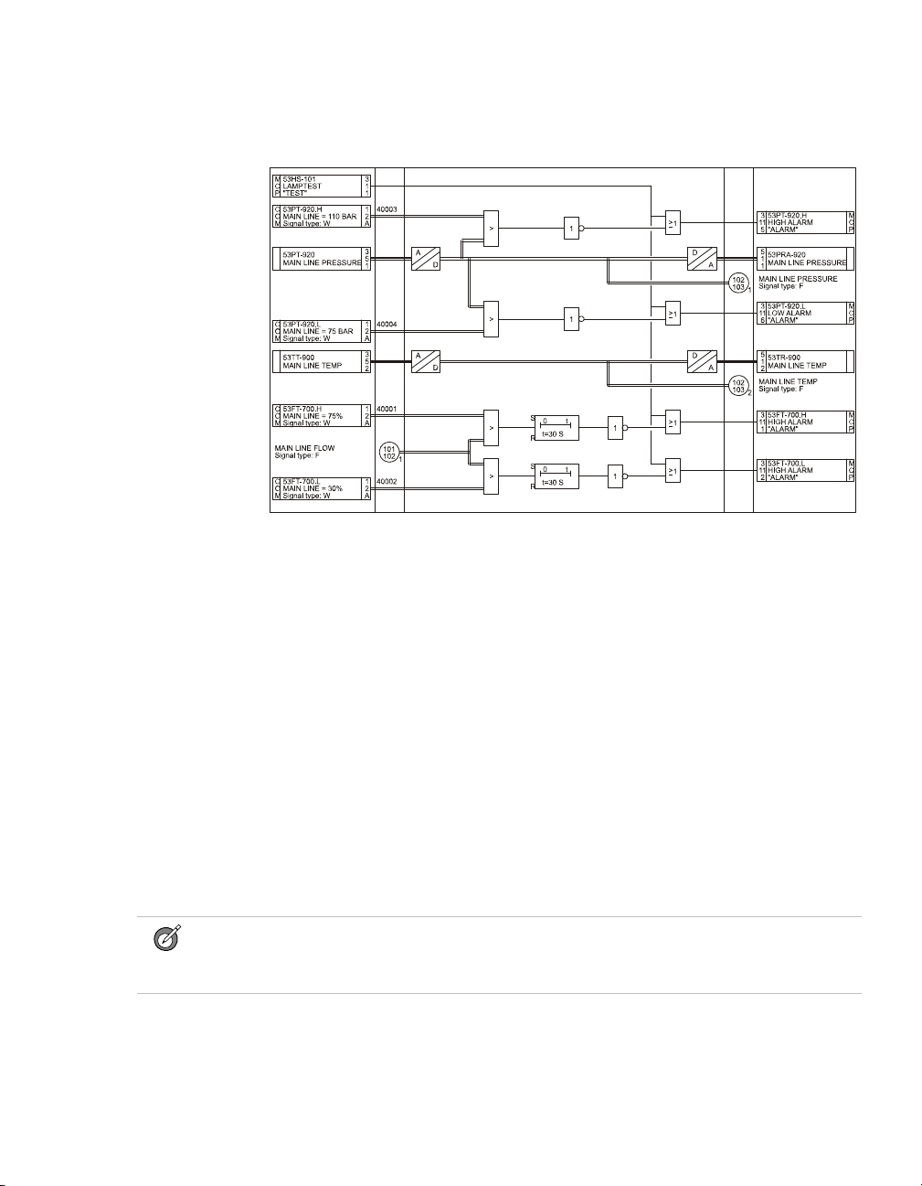
Figure 1 on page 5 shows how Safety Manager uses the graphical programming
method, based on Functional Block Diagram as defined by the IEC 61131-3.
4 Release 131, Issue 4
Page 11
Safety standards for Process & Equipment Under Control (PUC, EUC)
Figure 1 Example FLD layout
The IEC 61508 and IEC 61511 standards
SISs have been used for many years to perform safety instrumented functions e.g.
in chemical, petrochemical and gas plants. In order for instrumentation to be
effectively used for safety instrumented functions, it is essential that the
instrumentation meets certain minimum standards and performance levels.
To define the characteristics, main concepts and required performance levels,
standards IEC 61508 and IEC 61511 have been developed. The introduction of
Safety Integrity level (SIL) is one of the results of these standards.
This brief provides a short explanation of each standard. Detailed information
regarding IEC 61508 and 61511 can be found on the IEC web site
http://www.iec.org.
What standard to use?
Tip:
You can use the IEC 61508 as stand-alone standard for those sectors where a sector
specific standard does not exist.
Safety Manager Safety Manual 5
Page 12
1 – The Safety Manual
• If you are in the process sector and you are an owner/user, it is strongly
recommended that you pay attention to the IEC 61511 (ANSI/ISA 84.00.01).
For details see “IEC 61511, the standard for the process industry” on page 7.
• If you are in the process sector and you are a manufacturer, it is strongly
recommended that you pay attention to the IEC 61508. For details see “IEC
61508, the standard for all E/E/PE safety-related systems” on page 6.
• If you are in another sector, it is strongly recommended that you look for, and
use, your sector specific IEC standard for functional safety (if there is one). If
none exists, you can use the IEC 61508 instead. For details see “IEC 61508,
the standard for all E/E/PE safety-related systems” on page 6
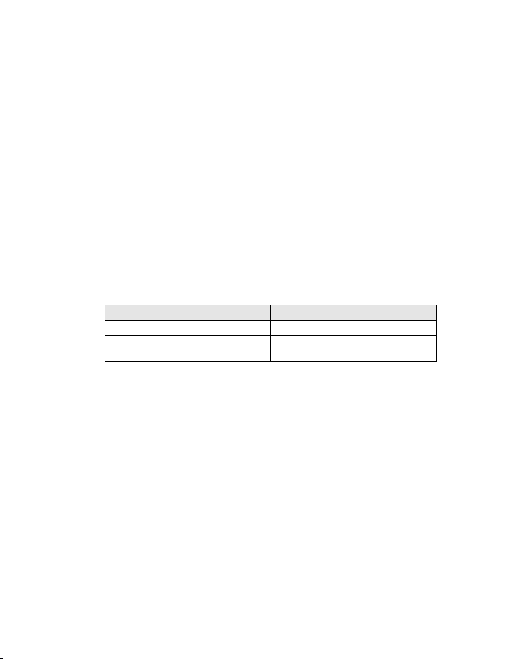
IEC 61508 and IEC 61511 terminology
This guide contains both IEC 61508 and IEC 61511 related terminology.
As the IEC 61511 sits within the framework of IEC 61508 most of the
terminology used may be interchanged. Table 1 on page 6 provides an overview
of the most common interchangeable terminology.
IEC 61508 terminology IEC 61511 terminology
safety function safety instrumented function
electrical/electronic/programmable
electronic (E/E/PE) safety-related system
Tab le 1 IEC 61508 versus IEC 61511 terminology
safety instrumented system (SIS)
IEC 61508, the standard for all E/E/PE safety-related systems
The IEC 61508 is called “Functional safety of
electrical/electronic/programmable electronic safety-related systems”
IEC 61508 covers all safety-related systems that are electrotechnical in nature
(i.e. electromechanical systems, solid-state electronic systems and
computer-based systems).
Generic standard
The standard is generic and is intended to provide guidance on how to develop
E/E/PE safety related devices as used in Safety Instrumented Systems (SIS).
The IEC 61508:
• serves as a basis for the development of sector standards (e.g. for the
machinery sector, the process sector, the nuclear sector, etc.).
• can serve as stand-alone standard for those sectors where a sector specific
standard does not exist.
6 Release 131, Issue 4
Page 13

Safety standards for Process & Equipment Under Control (PUC, EUC)
SIL
IEC 61508 details the design requirements for achieving the required Safety
Integrity Level (SIL).
The safety integrity requirements for each individual safety function may differ.
The safety function and SIL requirements are derived from the hazard analysis
and the risk assessment.
The higher the level of adapted safety integrity, the lower the likelihood of
dangerous failure of the SIS.
This standard also addresses the safety-related sensors and final elements
regardless of the technology used.
IEC 61511, the standard for the process industry
The IEC 61511 is called “Functional safety - Safety instrumented systems for the
process industry sector”. It is also referred to as the ANSI/ISA 84.00.01.
This standard addresses the application of SISs for the process industries. It
requires a process hazard and risk assessment to be carried out, to enable the
specification for SISs to be derived. In this standard a SIS includes all
components and subsystems necessary to carry out the safety instrumented
function from sensor(s) to final element(s).
The standard is intended to lead to a high level of consistency in underlying
principles, terminology and information within the process industries. This
should have both safety and economic benefits.
The IEC 61511 sits within the framework of IEC 61508.
Need to know more?
For more information regarding, or help on, implementing or determining, the
applied safety standards for your plant/process please contact your Honeywell
affiliate. Our Safety Consultants can help you to e.g.:
• perform a hazard risk analysis
• determine the SIL requirements
• design the Safety Instrumented System
• validate and verify the design
• train your local safety staff
Safety Manager Safety Manual 7
Page 14

1 – The Safety Manual
8 Release 131, Issue 4
Page 15

Architectural principle and standards of Safety Manager
Safety Manager basic architectures
Safety Manager can be configured for a number of architectures, each with its
own characteristics and typical Safety Instrumented Functions. Table 2 on page 9
provides an overview of the available architectures.
Tab le 2 Safety Manager architectures
Controller
configuration
Non-redundant
(DMR)
Redundant
(QMR)
IO configuration Remarks
Non-redundant DMR architecture;
• Non-redundant
• Redundant
• Redundant and non-redundant
2
Supports SIF for SIL1,
SIL2 and SIL3
applications.
QMR architecture;
Supports SIF for SIL1,
SIL2 and SIL3
applications.
Dual Modular Redundant (DMR) architecture
Typical applications of a DMR architecture are:
• Burner Management System
• Batch processing
• Machine protection
The Dual Modular Redundant (DMR) architecture provides 1oo2 voting in a
non-redundant system. The DMR architecture with 1oo2 voting is based on
dual-processor technology, and is characterized by a high level of self tests,
diagnostics and fault tolerance.
Safety Manager Safety Manual 9
Page 16
2 – Architectural principle and standards of Safety Manager
Processor
Processor
Watchdog
QPP Control Processor
SD
Input Interfaces Output Interfaces
Input
Module
Sensor
xx
yyy
Final Element
SMOD
Output
Module
The DMR architecture is realized with a non-redundant Controller. A
non-redundant architecture contains only one QPP (see Figure 2 on page 10),
which contains a redundant processor with 1oo2 voting between the processors
and memory.
Figure 2 Functional diagram: DMR architecture
In IO configurations, each path is primarily controlled by the Control Processor
and an independent switch (Secondary Means of De-energization, SMOD) which
is controlled by an independent watchdog.
Quadruple Modular Redundant (QMR) architecture
Typical applications of a QMR architecture are:
• process safeguarding applications for which continues operation is essential.
The Quadruple Modular Redundant (QMR) architecture is based on 2oo4D
voting, dual-processor technology in each QPP. This means that it is characterized
by a ultimate level of self diagnostics and fault tolerance.
The QMR architecture is realized with a redundant Controller. This redundant
architecture contains two QPPs (see Figure 3 on page 11), which results in
quadruple redundancy making it dual fault tolerant for safety.
The 2oo4D voting is realized by combining 1oo2 voting of both CPUs and
memory in each QPP, and 1oo2D voting between the two QPPs. Voting takes
place on two levels: on a module level and between the QPPs.
10 Release 131, Issue 4
Page 17
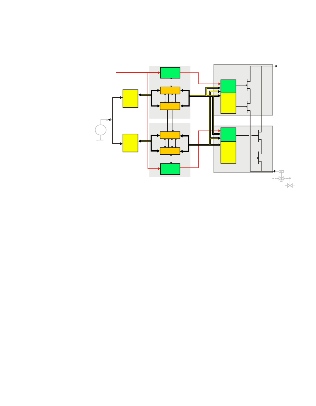
Figure 3 Functional diagram: QMR architecture
Input
Module
Input
Module
Processor
Processor
Watchdog
QPP Control Processor 1
QPP Control Processor 2
SD
Input Interfaces
SMOD
Output
Module
Final Element
Output Interfaces
SMOD
Output
Module
Quad
Vot er
Processor
Processor
Watchdog
Sensor
xx
yyy
In redundant IO configurations, each path is controlled by one of the Control
Processors and an independent switch (Secondary Means of De-energization,
SMOD), which is controlled by the diagnostic software and an independent
watchdog.
Furthermore, each Control Processor is able to switch off the output channels of
the other Control Processor.
Watchdog architecture in mixed IO configurations
In a system with combined redundant and non redundant IO 3 watchdog lines are
active:
• WD1
This is the Watchdog line dedicated for Control Processor 1.
- De-energizes upon a safety related fault in Control Processor 1 or an
output module of Control Processor 1.
- When de-energized, Control Processor 1 and the related outputs are halted.
•WD2
This is the Watchdog line dedicated for Control Processor 2.
Safety Manager Safety Manual 11
Page 18

2 – Architectural principle and standards of Safety Manager
Input
Module
Input
Module
Processor
Processor
Watchdog
QPP Control Processor 1
QPP Control Processor 2
SD
Input Interfaces
SMOD
Output
Module
Final Element
Output Interfaces
SMOD
Output
Module
Quad
Vote r
Processor
Processor
Watchdog
Input
Module
Final Element
SMOD
Output
Module
Sensor
xx
yyy
Sensor
xx
yyy
- De-energizes upon a safety related fault in Control Processor 2 or an
output module of Control Processor 2.
- When de-energized, Control Processor 2 and the related outputs are halted.
• WD3
This is the combined watchdog line, controlled by both Control Processors.
- De-energizes upon a safety related fault in a non redundant output.
- When de-energized, the non-redundant outputs are de-energized, but the
redundant outputs and the Control Processors remain operational.
Figure 4 Functional diagram: redundant Controller with redundant and non-redundant IO
12 Release 131, Issue 4
Page 19

Certification
The advantage of applying and complying to standards is obvious:
• International standards force companies to evaluate and develop their
• Products certified conform these international standards guarantee a certain
Since functional safety is the core of the Safety Manager design, the system has
been certified for use in safety applications all around the world. Safety Manager
has been developed specifically to comply with the IEC61508 functional safety
standards, and has been certified by TUV for use in SIL1 to SIL3 applications.
Safety Manager has also obtained certification in the United States for the UL
1998 and ANSI/ISA S84.01 standards.
For a full list of all these and other certifications see “Certification” on page 13.
Certification
Safety Manager has been certified to comply with the following standards:
Certification
products and processes according a consistent and uniform way.
degree of quality and product reliability that other products lack.
International Electrotechnical Commission (IEC) —
The design and development of Safety Manager are
compliant with IEC 61508 (as certified by TUV).
Instrument Society of America (ISA) — Certified to
fulfill the requirements laid down in ANSI/ISA S84.01.
CE compliance — Complies with CE directives
89/336/EEC (EMC) and 73/23/EEC (Low Voltage),
89/392/EEC (Machine Safety)
European Committee for Standardization — CEN,
CENELEC
Safety Manager Safety Manual 13
Page 20

2 – Architectural principle and standards of Safety Manager
TUV (Germany) — Certified to fulfill the requirements
of SIL3 safety equipment as defined in the following
documents: IEC61508, IEC60664-3, EN50156, EN 54-2,
EN50178, IEC 60068, IEC 61131-2, IEC 61131-3,
IEC60204.
Canadian Standards Association (CSA) — Complies
with the requirements of the following standards:
• CSA Standard C22.2 No. 0-M982 General
Requirements – Canadian Electrical Code, Part II;
• CSA Standard C22.2 No. 142-M1987 for Process
Control Equipment.
Underwriters Laboratories (UL) — Certified to fulfill
the requirements of UL 508, UL 991, UL 1998, and
ANSI/ISA S84.01.
Factory Mutual (FM) — Certified to fulfill the
requirements of FM 3611 and FM3600 (non-incentive
field wiring circuits for selected modules and installation
in Class 1 Div 2 environments).
14 Release 131, Issue 4
Page 21

Standards compliance
This subsection lists the standards Safety Manager complies with, and gives some
background information on the relevant CE marking (EMC directive and Low
Voltage directive).
Standard Title Remarks
IEC61508
(S84.01)
VDE 0116 (10/89) Electrical equipment of furnaces.
EN 54 part 2
(01/90)
EN 50081-2-1994 Electromagnetic compatibility –
EN 50082-2-1995 Electromagnetic compatibility –
IEC 61010-1-1993 Safety Requirements for Electrical
IEC 61131-2-1994 Programmable controllers. Part 2:
NFPA 72/2002 National Fire Alarm Code
NFPA 85/2001 Boiler and Combustions Systems
UL 1998 Safety-related software, first
UL 508 Industrial control equipment,
Functional safety of
electrical/electronic/
programmable electronic (E/E/PE)
safety-related systems.
(German title: Elektrische
Ausrüstung von
Feuerungsanlagen)
Components of automatic fire
detection systems, Introduction.
(German title: Bestandteile
automatischer
Brandmeldeanlagen)
Generic emission standard, Part 2:
Industrial environment.
Generic immunity standard, Part 2:
Industrial environment.
Equipment for Measurement,
Control and Laboratory Use, Part
1: General Requirements.
Equipment requirements and tests.
Handbook
Hazards Code
edition.
sixteenth edition.
Standards compliance
Table 3 Safety Manager compliance to standards
Underwriters Laboratories.
Underwriters Laboratories.
Safety Manager Safety Manual 15
Page 22

2 – Architectural principle and standards of Safety Manager
Tab le 3 Safety Manager compliance to standards
Standard Title Remarks
UL 991 Test for safety-related controls
employing solid-state devices,
second edition.
FM3600, FM 3611
Class I, Division 2,
Groups A, B, C &
D
Class II,
Division 2,
Groups F & G
CSA C22.2 Process control equipment.
IEC 60068-1 Basic environmental testing
IEC 60068-2-1 Cold test. 0°C (32°F); 16 hours; system in
IEC 60068-2-1 Cold test. –10°C (14°F); 16 hours; system
IEC 60068-2-2 Dry heat test. up to 65°C (149°F); 16 hours;
IEC 60068-2-3 Test Ca: damp heat, steady state. 21 days at +40°C (104°F), 93%
IEC 60068-2-3 Test Ca: damp heat, steady state. 96 hours at +40°C (104°F), 93%
IEC 60068-2-14 Test Na: change of temperature –
Electrical equipment for use in
• Class I, Division 2,
• Class II, Division 2, and
• Class III, Division 1 and 2,
hazardous locations.
Industrial products.
procedures.
withstand test.
Underwriters Laboratories.
Factory Mutual Research.
Applies to the field wiring
circuits of the following
modules:
SDI-1624, SAI-0410,
SAI-1620m, SDIL-1608 and
SAO-0220m, and installation of
the Controller in these
environments.
Canadian Standards Association
No. 142 (R1993).
operation; reduced power supply
voltage:
(–15%): U=20.4 Vdc or
(–10%): U=198 Vac.
in operation.
system in operation; increased
power supply voltage:
(+15%): U=27.6 Vdc or
(+10%): U=242 Vac.
relative humidity; function test
after cooling.
relative humidity; system in
operation.
–25°C—+55°C (–13°F—
+131°F), 12 hours, 95% relative
humidity, recovery time: max. 2
hours.
16 Release 131, Issue 4
Page 23

Table 3 Safety Manager compliance to standards
Standard Title Remarks
IEC 60068-2-30 Test Db variant 2: cyclic damp
heat test.
IEC 60068-2-6 Environmental testing – Part 2:
Tests – Test.
Fc: vibration (sinusoidal).
IEC 60068-2-27 Environmental testing – Part 2:
Tests – Test.
Ea: shock.
+25°C—+55°C (+77°F—
+131°F), 48 hours, 80-100%
relative humidity, recovery time:
1—2 hours.
Excitation: sine-shaped with
sliding frequency;
Frequency range: 10—150 Hz.
Loads:
• 10—57 Hz; 0.075 mm.
• 57—150 Hz; 1 G.
Duration: 10 cycles (20 sweeps)
per axis.
No. of axes: 3 (x, y, z).
Traverse rate: 1 oct/min in
operation.
Half sine shock.
2 shocks per 3 axes (6 in total).
Maximum acceleration: 15 G.
Shock duration: 11 ms.
Safety Manager in operation.
Standards compliance
Safety Manager Safety Manual 17
Page 24

2 – Architectural principle and standards of Safety Manager
18 Release 131, Issue 4
Page 25

Safety Manager fault detection and response
Introduction
The goal of fault detection and response is to detect and isolate any single fault
that affects the safety of the process under control, within a time frame that is
acceptable for the process.
Note:
There is always a diagnostic alarm available upon detection of a fault.
Diagnostic Test Interval
The Diagnostic Test interval (DTI) is the time in which detection and isolation of
faults takes place. The DTI must be set to a value that is acceptable for the
process, such as the Process Safety Time (PST). These values can be obtained
from hazard analysis reports.
3
FR state
The Fault Reaction (FR) state of each IO point is the predetermined state or action
the point assumes in case of faults.
• For normally energized safety related applications, like ESD applications, the
required predefined safe fault reaction state is de-energized or Low.
• For normally de-energized safety related applications, like FGS applications,
the required predefined safe fault reaction state for inputs is energized or
High / Top Scale.
Safety Manager Safety Manual 19
Page 26

3 – Safety Manager fault detection and response
Repair timer
Note:
The repair timer setting must be based on a hardware reliability analysis which includes
MTTR figures.
All configurations of Safety Manager are single fault tolerant towards faults that
affect safety: By using a secondary means Safety Manager is always able to bring
a process to safe state, regardless of the fault.
However, given some time, a second fault may occur. This second fault may then
disable the secondary means that keeps the process in a safe state.
To prevent such a scenario to develop, the system starts a repair timer if a
secondary means becomes vulnerable to faults. Once started, this configurable
timer counts down until the fault is repaired. If the timer is allowed to reach zero,
the Control Processor halts.
20 Release 131, Issue 4
Page 27

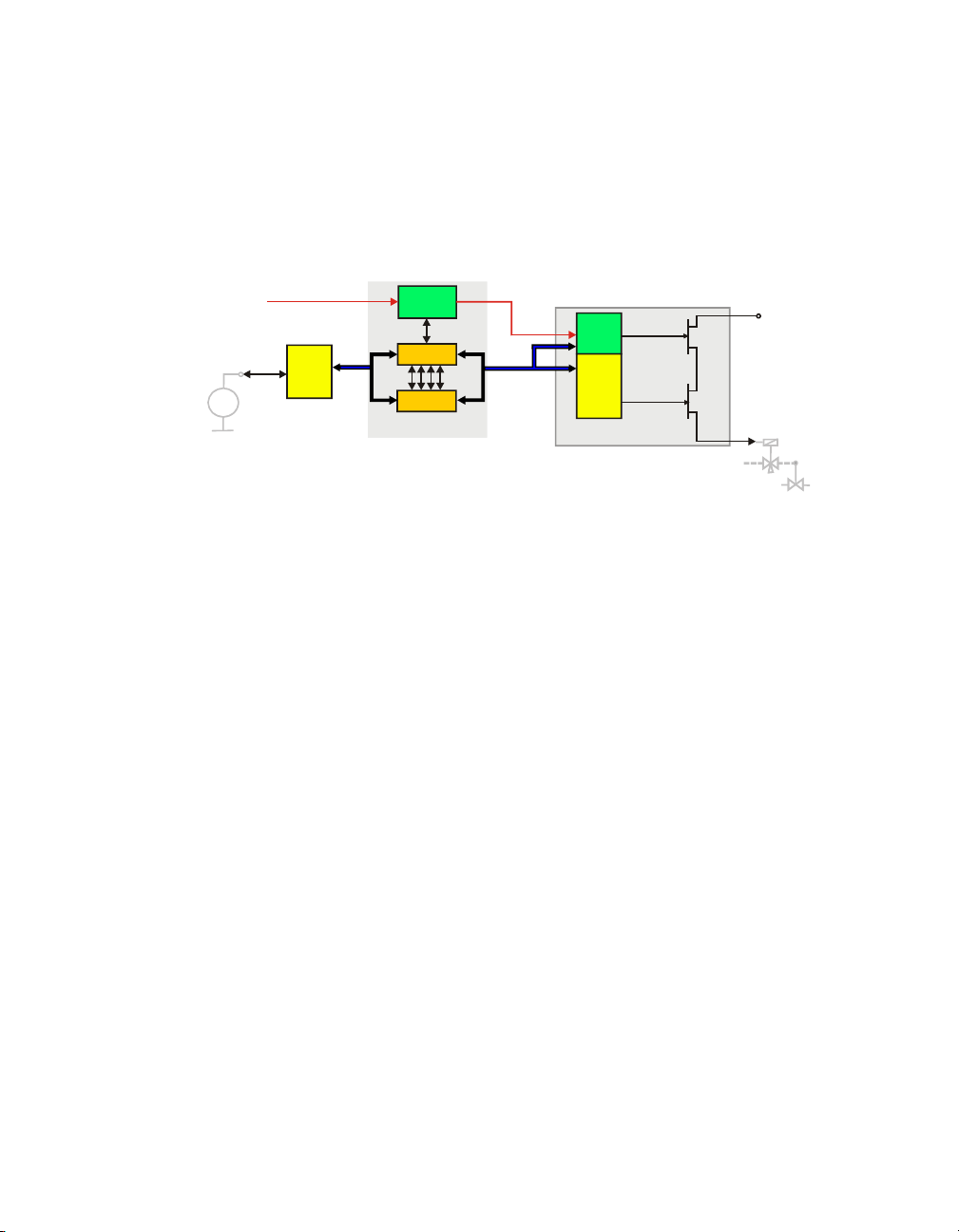
Shutdown at assertion of Safety Manager alarm markers
If the normal system response of Safety Manager is not enough when Safety
Manager detects a fault and more stringent system response is required, the Safety
Manager alarm markers can be used to shut down the system via the application.
Figure 5 on page 21 shows an example of how to shut down the system in case of
an IO compare error. An additional manual shutdown input is provided by which
the operator can initiate a shutdown by hand.
Figure 5 Diagram to shut down system in case of output compare error
If an IO compare error is detected or a manual shutdown is initiated, a
divide-by-zero is forced and Safety Manager shuts down. Other alarm markers
can be used in a similar way.
Note:
A manual shutdown can also be realized via the shutdown (SD) input of the
SM Controller.
With aid of the SD input a tested, hard wired connection can be used. The SD input is
accessible via the SD loop connector at the back of the CP chassis.
Breaking the SD loop causes all outputs to be de-activated!
Safety Manager Safety Manual 21
Page 28

3 – Safety Manager fault detection and response
SM Controller faults
Below topics provide an overview of detected Controller faults and the Controller
response to these faults.
QPP faults
Table 4 on page 22 provides an overview of faults that the Controller detects
related to the QPP and the response to these faults.
Tab le 4 Controller response to QPP faults
QPP faults Non redundant
related to diagnostics report includes CP
temperature monitoring
(set points user
configurable)
Memory QPP memory halt Controller halt CP none -continue
Execution execution time out of
Watchdog output shorted halt Controller halt CP none -continue
Watchdog faulty halt Controller halt CP none -continue
Bus drivers
Internal link
QPP module
secondary switch-off faulty halt Controller halt CP none -continue
high alarm or low alarm none -continue none -continue
high-high alarm or
low-low alarm
1 sensor faulty and temp.
more than 3 degrees from
shutdown limits
1 sensor faulty and temp.
less than 3 degrees from
shutdown limits
range / failure
error on logical sheet halt Controller
de-energized watchdog
line for redundant outputs
de-energized watchdog
line for non-redundant
outputs
Controller
response
halt Controller halt CP none -continue
none -continue none -continue
halt Controller halt CP none -continue
halt Controller halt CP none -continue
halt Controller halt CP none -continue
halt Controller de-energize non redundant outputs,
Redundant Controller response
X( faulty)
continue operation on redundant
outputs
CP
Y (not faulty)
22 Release 131, Issue 4
Page 29

Tab le 4 Controller response to QPP faults (continued)
SM Controller faults
QPP faults Non redundant
related to diagnostics report includes CP
repair timer
(user configurable)
software corrupted halt Controller halt CP none -continue
intervention QPP key switch to IDLE
synchronization QPP n.a. halt CP none -continue
time sync
(user configurable)
internal communication n.a. halt CP none -continue
running none -continue none -continue
expired halt Controller halt CP none -continue
position
Spurious watchdog
interrupt
safe state initiated
SD input de-energized halt Controller
system software halted CP does
base timer halt CP none -continue
IO compare error apply FR state
source unavailable switch to other
Controller
response
halt Controller halt CP none -continue
source
Redundant Controller response
X( faulty)
not start
switch to other source
CP
Y (not faulty)
none -continue
USI faults
Table 5 on page 24 provides an overview of detected faults in relation to the USI
and the response to these faults.
A fault in the USI also means that the communication channels of that USI are
down.
Safety Manager Safety Manual 23
Page 30

3 – Safety Manager fault detection and response
Tab le 5 Controller response to USI faults
USI faults Non redundant
related to diagnostics report
includes
Memory USI module apply FR state to
Execution
communication USI module
module faulty USI module
synchronization system software
software corrupted
* If values are not available via CPY apply FR state to affected COM & FSC inputs.
Controller
response
affected COM &
FSC inputs
Redundant Controller response
CP
X( faulty)
use values from
for affected
CP
Y
COM & FSC
*
inputs.
BKM faults
Table 6 on page 24 provides an overview of faults that can be detected in relation
to the BKM and the response to these faults.
Table 6 Controller response to BKM faults
BKM faults Non redundant
related to diagnostics report includes CP
key switch input compare error
(reset key switch)
input compare error
(force key switch)
module faulty BKM module none -continue none -continue
battery faulty / low none -continue none -continue
lifetime expired
transport switch
Controller
response
none -continue none -continue
Redundant Controller response
X( faulty)
CP
Y (not faulty)
none
CP
Y (not faulty)
PSU faults
Table 7 on page 25 provides an overview of faults that can be detected in relation
to the PSU and the response to these faults.
24 Release 131, Issue 4
Page 31

Table 7 Controller response to PSU faults
SM Controller faults
PSU faults Non redundant
related to diagnostics report includes CP
Controller
response
Redundant Controller response
X( faulty)
CP
Y (not faulty)
Voltage monitoring spurious watchdog interrupt halt Controller halt CP none -continue
module faulty PSU module
Communication faults
Note
Please note that a fault in the communication links may be caused by USI modules.
Table 9 on page 27 provides an overview of faults that can be detected in relation
to communication and the response to these faults.
Tab le 8 Controller response to communication faults
communication faults Non redundant
communication or
“shared CP”
Related to Diagnostic message
reports
broken link communication
wrong protocol assigned
fault
time-out
Controller
response
*
apply FR state to
COM & FSC inputs
of that channel
if channel belongs
to active clock
source, switch to
other clock source
too many data requests USI module faulty apply FR state to
COM & FSC inputs
of that USI
data mismatch between
****
inputs
compare error n.a. apply FR state
(SafeNet redundant)
data mismatch between
n.a. values received by CP2 prevail.
inputs****
(redundant Experion or
Modbus)
Redundant communication
Controller response
CP
X(faulty)
continue
communication via
healthy link
**
CP
Y(not faulty
none -continue
use values from
for affected
CP
Y
COM and FSC
***
inputs
Safety Manager Safety Manual 25
Page 32

3 – Safety Manager fault detection and response
* If the Controller is redundant, both CP channels respond the same.
** If no healthy link remains, apply FR state to the COM and FSC inputs allocated to that channel and/or switch to other
clock source.
*** If values are not available via CP
**** Inputs as in communication inputs of this SM Controller.
apply FR state to affected COM and FSC inputs.
Y
Communication time-out
If no communication with the external device is established within a predefined
time frame a communication time-out is generated.
A communication time-out always results in a communication failure.
Communication time-outs can be configured by the user.
If a device is connected to Safety Manager via a redundant communication link,
the fault detection applies to each link separately resulting in single-fault tolerant
communication.
26 Release 131, Issue 4
Page 33

SM IO faults
Tip:
For more information on repair timer settings or fault reaction states as referred to in these
topics, see “Introduction” on page 19.
These topics provide an overview of detected IO faults and the Controller
response to these faults.
Digital input faults
Table 9 on page 27 provides an overview of faults that can be detected in relation
to digital inputs and the response to these faults.
SM IO faults
Table 9 Controller response to digital input faults
Digital input faults Non redundant input
Related to Diagnostic message
reports
digital input loop
(line monitored)
loop power** power output to sensors
channel module faulty apply FR state use values from
module module faulty apply FR state use values from
compare
****
* If the Controller is redundant, both CPs respond the same.
** This fault is usually caused by an anomaly in the field, not by a defect of an input module.
*** If values are not available via CPY apply FR state to affected inputs.
**** Occurs when detecting a difference in the input values persists for more than 2 application cycli.
**
lead breakage apply FR state apply FR state
short circuit
shorted
input compare error apply FR state apply FR state
Controller response
apply FR state use values from
Redundant input, Controller response
*
CPX (faulty input) CPY (healthy input)
***
CP
Y
CPY***
CP
***
Y
none -continue
none -continue
none -continue
Safety Manager Safety Manual 27
Page 34

3 – Safety Manager fault detection and response
Analog input faults
Table 10 on page 28 provides an overview of faults that can be detected in
relation to analog inputs and the response to these faults.
Table 10 Controller response to analog input faults
Analog input faults Non redundant input
Related to Diagnostic message
Controller response
Redundant input, Controller response
*
CPX (faulty input) CPY (healthy input)
reports
analog input value below low transmitter
alarm level per range
none- continue for
0-20mA, 0-10V
bottom scale for
none- continue for 0-20mA, 0-10V
bottom scale for 4-20mA, 2-10V
4-20mA, 2-10V
above high transmitter
none- continue none- continue
alarm level all ranges
loop power
(SAI-1620m)
channel module faulty apply FR state use values from
External voltage
monitoring fault
none- continue none- continue
**
CP
Y
module module faulty apply FR state use values from
CP
Internal power down
compare
***
* If the Controller is redundant, both CPs respond the same.
** If values are not available via CPY apply FR state to affected inputs.
*** Occurs when detecting a deviation of >2% in the input values persists for more than 2 application cycles.
input compare error apply FR state apply FR state
Y***
Digital output faults
none- continue
none- continue
Table 11 on page 28 provides an overview of faults that can be detected in
relation to digital outputs and the response to these faults.
Tab le 11 Controller response to digital output faults
Digital output faults Non redundant output
Related to Diagnostic message
reports
digital output loop
**
current detected Apply FR state apply FR state
(line monitored)
default voting
28 Release 131, Issue 4
Controller response
Redundant output, Controller response
*
CPX (faulty output) CPY (healthy output)
Page 35

Tab le 11 Controller response to digital output faults (continued)
SM IO faults
Digital output faults Non redundant output
Related to Diagnostic message
Controller response
reports
digital output loop**
(line monitored)
current detected De-energize shorted
output(s).
1oo2D voting
digital output loop**
open loop none -continue none -continue
(line monitored)
digital output loop**
(other)
loop power
***
channel fault
(line monitored)
FR state = Low
channel fault
(other)
FR state = Low
channel fault
short circuit detected De-energize shorted
output(s).
external power down none -continue none -continue
module faulty De-energize outputs
on module & start
repair timer
module faulty De-energize outputs
on module & start
repair timer
module faulty none -continue none -continue
Other FR states
module fault
FR state = Low
module faulty De-energize outputs
on module & start
repair timer
module fault
module faulty none -continue none -continue
Other FR states
compare
****
output compare error apply FR state apply FR state
Redundant output, Controller response
*
CPX (faulty output) CPY (healthy output)
de-energize shorted output(s).
de-energize shorted output(s).
De-energize outputs on module & start
repair timer
De-energize outputs
none -continue
on module & start
repair timer
De-energize outputs
none -continue
on module & start
repair timer
* If the Controller is redundant, both CPs respond the same.
** This fault is usually caused by an anomaly in the field, not by a defect of an output module.
*** When this anomaly occurs on all modules in a watchdog group or a power group, it is not a defect of the output module.
**** Occurs when detecting a difference in the output values of a redundant SM Controller.
Analog output faults
Table 12 on page 30 provides an overview of faults that can be detected in
relation to analog outputs and the response to these faults.
Safety Manager Safety Manual 29
Page 36

3 – Safety Manager fault detection and response
Table 12 Controller response to analog output faults
Analog output faults Non redundant output
Related to Diagnostic message
reports
analog output calculation error halt Controller halt Controller
analog output loop open loop De-energize outputs
channel fault
FR state = 0 mA
channel fault
Other FR states
module fault
FR state = 0 mA
module fault
Other FR states
compare
**
* If the Controller is redundant, both CPs respond the same.
** Occurs when detecting a difference in the output values of a redundant SM Controller.
module faulty De-energize outputs
module faulty none -continue none -continue
module faulty De-energize outputs
module faulty none -continue none -continue
output compare error Apply FR state Apply FR state
Controller response
on module & start
repair timer
on module & start
repair timer
on module & start
repair timer
Redundant output, Controller response
*
CPX (faulty output) CPY (healthy output)
none -continue
De-energize outputs
on module & start
repair timer
De-energize outputs
on module & start
repair timer
IO compare errors and system response
none -continue
none -continue
Note
Because of the high level of self-testing and fault-handling by Safety Manager, the actual
occurrence of a compare error is very unlikely.
For proper operation both Control Processors of a redundant system must have
identical IO values at the beginning and at the end of each application cycle.
An IO compare error is generated as soon as the Controller detects a difference
between the IO values of CP1 and CP2.
The Controller responds towards IO compare errors by applying the fault reaction
state to the faulty IO.
Note
A Controller does not automatically shut-down upon detection of IO compare error.
30 Release 131, Issue 4
Page 37

Table 13 on page 31 shows the relation between Input and output compare faults,
alarm markers and Controller response.
Tab le 13 Controller response to IO compare faults
IO compare error
Related to redun
digital inputs N.A. a persisting difference for more than 2
analog inputs N.A. a deviation of >2% for more than 2
digital
outputs
analog
outputs
Occurs when detecting Controller
dancy
application cycles
application cycles.
N.A. a difference between outputs
N.A.
Compare error detection and synchronization
Input compare errors
Input compare error detection applies to all hardware inputs.
Differences in the input status read should be momentary. Persisting differences
could be the result of detected hardware faults. In that case, the faulty input
channel is reported in the diagnostics, and both Control Processors use the
process value read from the healthy input channel.
A persisting difference in status of an input while no faults are detected at the
accessory hardware channels leads to an input compare error.
SM IO faults
response
apply FR
state
Output compare errors
An output compare error applies to all hardware outputs.
In configurations with a redundant Controller, both Control Processors will
continuously have an identical application status, resulting in identical process
outputs.
An output compare error is detected if there is a difference between the Control
Processors with respect to:
• the calculated application output values for hardware outputs (AO/DO) or
• the actual application values sent to hardware outputs (AO/DO) or
communication outputs (DO, BO) to another Safety Manager.
communication outputs (DO, BO) to another Safety Manager.
Safety Manager Safety Manual 31
Page 38

3 – Safety Manager fault detection and response
If outputs are no longer synchronized an Output Compare error is generated.
Input synchronization algorithm
In configurations with a redundant Controller, the process inputs are scanned
every application program cycle by both Control Processors.
Each Control Processor executes the application cycle independently of the other.
It is therefore essential that they use identical values for the process inputs.
There is no problem if the process inputs are stable. However, if an input value
changes when the Control Processors read the value, both Control Processors
could read a different value. In such cases, an identical input value in the
Controller is obtained via input synchronization.
If inputs are no longer synchronized, the signal value freezes to the last known
synchronized state and a synchronization timer -equal to two application cyclesis started. This state is maintained until:
• a synchronized state is obtained or
• the synchronization timer runs out.
If a synchronized state is not achieved within two application cycles the fault
reaction is activated and an Input Compare error is generated.
If a synchronized state is achieved within two application cycles the
synchronization timer is reset.
Synchronization algorithms are used for digital and analog inputs.
Digital input synchronization
A digital input compare error is detected if the inputs of both Control Processors
are stable but different (for example Control Processor 1 continuously ‘0’,
Control Processor 2 continuously ‘1’), for the duration of two application cycles.
The input compare error detection algorithm puts the following demands on the
dynamic nature of the digital process inputs:
1. If an input state changes, it must become stable again within two application
cycles.
2. The frequency of continuously changing inputs must be less than two
application cycles.
Analog input synchronization
For analog inputs, the synchronized value is the mean value of the input values.
An input compare error is detected if the input values differ more than 2% of the
full scale for the duration of the configured Diagnostic Test Interval.
32 Release 131, Issue 4
Page 39

SM IO faults
The input compare error detection algorithm puts the following demands on the
dynamic nature of the analog process inputs:
1. For inputs allocated on a redundant module (type SAI-0410 or SAI-1620m),
the slope steepness must be less than 125 mA/s.
2. For inputs allocated on a non-redundant module (type SAI-1620m), the slope
steepness must be less than 20 mA/s
.
Caution
Analog input compare errors may, for example, occur when calibrating smart transmitters
using hand-held terminals. Refer to the Troubleshooting and Maintenance Guide for
details on calibrating smart transmitters that are connected to Safety Manager analog
inputs.
Safety Manager Safety Manual 33
Page 40

3 – Safety Manager fault detection and response
Calculation errors
Caution
Safety Manager stops if a calculation error occurs.
Calculation errors may occur in the application program.
Calculation errors occur if:
• The calculated value of an analog output is outside the specified range.
• The square root of a negative number is taken.
• A logarithm function is loaded with a negative value or zero
• A divide-by-zero occurs.
• An overflow occurs during a calculation.
• The value for a counter is outside the specified range.
Calculation errors reflect an incorrect design of the application program for the
intended function. Once a calculation error occurs for a specific process point, a
correct result of successive calculations based on this point cannot be guaranteed.
Guidelines on how to avoid calculation errors in the Safety Manager application
are presented below.
Preventing calculation errors
Calculation errors can be prevented as follows:
• Overall process design.
• Inclusion of Safety Manager diagnostic data.
• Validation of signals in the Functional Logic Diagrams (FLDs).
• Exception handling during the actual calculation.
Prevention by design
In line with good software engineering practice, as promoted by IEC 61508,
calculation errors should be avoided by design. This means that an application
should be designed in such a way that the operands of a symbol in the FLDs can
never get an invalid value. The design approach starts with making sure that input
values as obtained from the process remain within a predefined range. This
approach ensures that the derived values are also valid for successive operations.
34 Release 131, Issue 4
Page 41

Sometimes, however, it cannot be guaranteed that an input value remains within a
Transmitter
Transmitter
Validated
input value
Alarm/
Annunciation
Process
value
predefined range which is valid for all functions. For example, a signal derived
from a reverse-acting, non-linear 4-20 mA transmitter which has been configured
for a zero top scale in the application domain could become negative if the
transmitter fails and delivers a signal beyond 20 mA. If the signal is then
linearized through a square-root function, a system stop occurs (square root of
negative number).
Preventive measures
If a valid input value cannot be guaranteed, preventive measures must be built
into the design. A comparison function can be used as an indicator that the
transmitter value has left its normal operational band and that the calculation
should not be done. The alarm signal is used to implement a corrective action and
to indicate the exception to the operator (see Figure 7 on page 35).
Calculation errors
Figure 6 Intended square-root function
Figure 7 Square-root function with validated input value
If diagnostics are not available (e.g. for 0-20 mA transmitters), it is necessary to
implement range checking in the application. The result of the range check is
again used for the implementation of corrective actions.
Tip
Range checking is also useful to define the boundaries of analog outputs 0(4)-20mA, thus
preventing a system shutdown due to driving values that exceed the boundaries.
Safety Manager Safety Manual 35
Page 42

3 – Safety Manager fault detection and response
Transmitter
Function block
Alarm/
Annunciation
Process
value
An important advantage of input validation is that it can be implemented for input
values of which the validity cannot be guaranteed. Furthermore, the invalid input
can be exactly identified. This allows the implementation of effective correction
strategies of only the affected part of the process.
Common function block
A last option is to create a common function block, e.g. square root. The function
block validates the operand(s) and only performs the intended function if the
operands are valid. Otherwise a predefined value is returned. An additional
function block output should be provided which indicates if the calculation result
is valid or not. This output signal can be used for the implementation of corrective
actions in the application (see Figure 8 on page 36).
Figure 8 Square-root function with validity check in function block
36 Release 131, Issue 4
Page 43

Safety Manager special functions
Unit shutdown
Process units
If a process can be divided into independent process units, the overall process
availability can be increased by a separate shutdown of the units within Safety
Manager. In this way, whenever a fault is detected in the hardware of a process
unit, only the affected unit needs to be shut down, while the other parts of the
process remain unaffected.
Configuration of unit shutdown (watchdog grouping)
This subsection covers the required configuration, application programming and
wiring to achieve shutdown per process unit.
Figure 9 on page 38 shows a standard wiring diagram for unit shutdown of three
separate process units.
4
Safety Manager Safety Manual 37
Page 44

4 – Safety Manager special functions
Safety Manager
9236295192362951
Watchdog signal
Relay Relay Relay
Safe
"Relay-controlling"
Digital
Output module
Safe "Process”
Digital Output modules
For each process unit, a relay is used to connect the watchdog signal of the unit
output to the process Safety Manager watchdog. The relays are controlled via
outputs of Safety Manager: the unit shutdown outputs. In normal operation, all
relays are activated. If a fault is detected in a process unit, the corresponding relay
is deactivated, which results in a shutdown of the relevant unit.
The unit relays must meet the requirements of DIN VDE 0116, part 8.7.4.5 and
8.7.4.6 of October 1989, i.e.:
1. Mechanical reliability > 3 ∗ 10
2. Contacts protected (for example fuses, series resistors, etc.) at 0.6 ∗ nominal
contact current.
3. Electrical reliability > 2.5 ∗ 10
Tip
The relay output FTA TSRO-0824 complies to these requirements.
Figure 9 Wiring diagram for unit shutdown
6
switches.
5
switches.
38 Release 131, Issue 4
Page 45

Unit shutdown outputs
The unit shutdown outputs must:
• Be allocated on safe modules (such as a SDO-0824 or SDOL-0424 module)
• Have their fault reaction state set to Low.
This guarantees that Safety Manager directs the process to its safe state if a
fault occurs which affects this output.
• Have set the power-up status of the unit shutdown output to ON.
This allows a correct start-up of Safety Manager with activated unit relays.
For optimal availability it is recommended that unit shutdown outputs are
allocated to redundant output modules.
Process outputs (safety related)
The process outputs must be allocated to a Safety Manager output module of the
type:
•SDO-0824
• SAO-0220m
•SDO-04110
•SDO-0448
•SDO-0424
• SDOL-0424
• SDOL-0448
To allow the programming of the response via the application, the fault reaction
of these outputs must be set to Appl. This disables the automatic response of
Safety Manager in case a fault occurs at safety-related output modules.
Application programming
To realize unit shutdown in the functional logic diagrams, all diagnostic inputs
related to output modules of each process unit are connected to an AND gate.
Safety-related digital output module
(24 Vdc, 0.55 A, 8 channels)
Safety-related analog output module
(0(4)-20 mA, 2 channels)
Safety-related digital output module
(110 Vdc, 0.32 A, 4 channels)
Safety-related digital output module
(48 Vdc, 0.75 A, 4 channels)
Safety-related digital output module
(24 Vdc, 2 A, 4 channels)
Safety-related loop-monitored digital output module
(24 Vdc, 1 A, 4 channels)
Safety-related loop-monitored digital output module
(48 Vdc, 0.5A, 4 channels
Safety Manager Safety Manual 39
Page 46

4 – Safety Manager special functions
Figure 10 on page 40 shows how the output signal of the AND gate is connected
to the unit shutdown.
As long as all diagnostic inputs are “healthy”, they are High, the unit shutdown
output is High and the unit relay is activated (relay contact closed).
If a diagnostic input of an output channel in the unit becomes “unhealthy”, the
corresponding unit shutdown output becomes Low and the unit relay is
deactivated (relay contact open).
Figure 10 Functional logic diagram of unit shutdown
A defective output channel can be switched-off in accordance with the normal
Safety Manager response for safety-related signals. To switch off a defective
output channel, the calculated application output and the channel diagnostic input
must be supplied to the output channel via an AND gate.
The Safety Manager FaultReset alarm marker is connected to all unit
shutdown outputs via an OR gate. When an error is detected and repaired in a
unit, the unit may be restarted using the FaultReset alarm marker.
The minimum and maximum time the unit output is enabled by the
FaultReset is limited to ensure that the FaultReset is detected by the
output. The pulse length (typically set at 800 ms) may not exceed the Diagnostic
Test Interval.
40 Release 131, Issue 4
Page 47

On-line modification
Tip:
Detailed information about On-line modification can be found in On-line Modification
Guide
Introduction
On-line modification (OLM) is a Safety Manager option which allows you to
modify the application software, embedded system software and the Safety
Manager hardware configuration of systems with a redundant Controller while
the system remains operational.
During the on-line modification, the changes are implemented in the Control
Processors one by one. While one Control Processor is being modified, the other
Control Processor continues safeguarding the process.
The engineer executing the OLM is guided through the OLM procedure step by
step by Controller Management which is integrated in the Safety Builder.
On-line modification
Compatibility check
During the modification, Safety Manager performs a compatibility check of the
application-related data, to guarantee a safe changeover from the existing
configuration to the new configuration. The system reports all application
changes in a detailed report in the Extended Diagnostics.
The user is expected to verify each reported change before starting up the system.
When modifications are implemented in an application, only a functional logic
test of the modified functions is required by, for example, TUV. This must be
done when the final verification of the implemented changes is obtained via the
built-in sheet difference report in Controller Management diagnostics.
Safety Manager networks
If a system has been integrated into a Safety Manager communication network
(SafeNet), it performs a compatibility check for all connected systems.
If it detects inconsistencies or if the check of a specific system cannot be
completed for some reason, an error message is generated in the extended
diagnostics. In case such an error occurs, no data will be exchanged with that
system. The communication can only be established after a successful completion
of the compatibility check by any of the Safety Managers that can communicate
with each other, initiated via a QPP reset.
Safety Manager Safety Manual 41
Page 48

4 – Safety Manager special functions
SafeNet communication
Safety Managers can be connected together to form safety-related networks. The
protocol used for this network is called SafeNet.
SafeNet is available to Safety Managers for:
• Distributed processing
• Sharing safe data for joint SIS related tasks.
• SIL3, TUV approved, communication.
• Remote load
Networks
Attention:
USIs running 3
USI outages and communication shutdown.
If communication overflow is a potential risk, we recommend to allocate all SafeNet links
on dedicated USIs (not running vulnerable 3
rd
party protocols may be vulnerable to communication overflow, causing
rd
party protocols).
Data that is transferred between Safety Managers is represented in function logic
diagrams as IO symbols with the location FSC. Points with location FSC can be
of type DI or DO (markers), BI or BO (registers), and may be configured for safe
and non-safe functions.
Protocol versus response time
The response time between Node ID and logical Peer ID depends on:
• the application program cycle time of the Node ID and Peer ID system in the
logical link.
• the delay caused by the data layer protocol of the physical links.
Response time and time-out time are related.
The minimum time-out depends on the system application cycle and the type of
communication link.
The time-out time you set must be larger than the maximum response time.
The response time to a communication request highly depends on the actual states
of both Node ID and Peer ID system at the time of the request.
42 Release 131, Issue 4
Page 49

The maximum response time equals the sum of:
• the application cycle time of the Node ID plus
• the application cycle time of the Peer ID plus
• the expected communication delay.
The Node ID periodically sends data to the Peer ID systems and initiates a request
for data from the Peer IDs. A correct answer must be provided for within the
time-out period; when not received in time, the link is regarded faulty.
A new data transmission and request for a Peer ID are initiated after the Peer ID
reply to the previous request has been received. This could be equal to the
time-out time, but usually it is shorter.
SafeNet time-out time
All systems within the network monitor the operation of a communication link by
means of a time-out.
• The time-out can be set for each individual logical link and must be chosen
• The time-out time set must be at least 2x the calculated response time.
SafeNet communication
such that it stays within the Process Safety Time (PST) for the Safety
Instrumented Functions (SIFs) involved.
Ethernet communication
When communicating via Ethernet you should be aware of the following:
• “Ethernet communication risks” on page 43
• “Ethernet bandwidth and response time calculation” on page 44
Ethernet communication risks
Attention:
USIs running 3
USI outages and communication shutdown.
If communication overflow is a potential risk, we recommend to allocate all SafeNet links
on dedicated USIs (not running vulnerable 3
When devices communicate via an Ethernet based local area network (LAN),
their information is contained and sent in packets. This is no different when using
SafeNet through Ethernet. However, Ethernet has far less timing restrictions and,
when sending SafeNet packets together with other application packets, some
packets may suffer critical delay or get lost if a network gets congested.
rd
party protocols may be vulnerable to communication overflow, causing
rd
party protocols).
Safety Manager Safety Manual 43
Page 50

4 – Safety Manager special functions
Packet losses and network congestion may occur if e.g.:
• several devices start transmitting packets at the same time and/or,
• a single device generates a peak in network traffic,
Attention:
1. Risks are involved when using SafeNet on an insecure, open or shared Ethernet,
where downtime, delays, loss and/or access to packets can be caused by other devices
on the LAN.
Such risks can be caused by office computers, network printers, servers and open
access points (such as wifi access points, WAN routers, etc.)
2. Viruses and applications such as MSN Messenger may affect SafeNet reliability when
active on the same Ethernet.
When the Ethernet is dedicated to a single Safenet, issues do not take place:
• No single SafeNet configuration can cause a 100MB Ethernet to operate at its
maximum capacity (Safety Builder checks this in the configuration stage).
Packets are vulnerable to modifications or alterations when accessed by external
systems: Applications running on these systems could (deliberately or via a virus
infection) intercept, delay and/or alter packets.
Ethernet bandwidth and response time calculation
Please consult the release notes issued with your Safety Builder software for ways
to determine bandwidth and response time.
Conventional serial communication
Please consult the release notes issued with your Safety Builder software for ways
to determine bandwidth and response time.
Reset
The reset function is a means to allow Safety Manager to recover from an
abnormal state. (Running fault free is the normal operating state.)
Safety related resets allow the recovery from all fault types whereas non safety
related resets allow the recovery of non safety related faults only.
Safety related resets can be given via the reset key switch, via the Remote
Reset button in Safety Builder (after enabling in the configuration) and by
SM Controllers, initiating a safety related reset command via SafeNet.
44 Release 131, Issue 4
Page 51

System response towards a safety related reset
The response to a safety related reset action depends on the QPP state of the
Control Processor. The following QPP states make the Control Processor respond
to a reset:
1. Running
The Control Processor is running without faults.
Initiating a reset will have no effect on the SM Controller state.
2. Running with Flt
The Control Processor is running with faults.
Initiating a reset will move the faults logged in the actual fault database to the
historical fault database (clearing the actual faults database) and log the reset.
3. CPReady (after startup or after recovering from a fault)
(Both Control Processors contain the same application.)
Initiating a reset, with a QPP in CPReady and identical applications residing
in CP1 and CP2, will start the application in the ready QPP.
4. CPReady (during an OLM procedure)
(Both Control Processors contain different applications.)
Initiating a reset with a QPP in CPReady and different applications in the
Control Processors (OLM) will cause an application switch-over from the
running Control Processor to the ready (idle) Control Processor.
5. Halt with Flt (during an OLM procedure)
(Both Control Processors contain different applications.)
The Control Processor was halted due to a fault detected during the OLM
compatibility check procedure. Initiating a reset will clear the fault database,
run a new diagnostic cycle and log the result in the fault database.
a. The QPP remains in the Halt with Flt state if faults are detected
during the diagnostic cycle;
b. The QPP goes to the CPReady (during OLM) state if no faults are
detected.
SafeNet communication
Safety Manager Safety Manual 45
Page 52

4 – Safety Manager special functions
46 Release 131, Issue 4
Page 53

Special requirements for TUV-approved applications
General
Safety Manager can be used for processes which require, amongst others, TUV
approval. The requirements for the safety applications are the following:
1. The maximum application cycle time is half the Process Safety Time. For
example, the accepted Process Safety Time for a burner control system in
accordance with TRD-411 for boilers > 30 kW (July 1985) Table 1, TRD-412
(July 1985) Table 1 and DIN 4788 (June 1977) Part 2 Chapter 3.2.3.2 1 is 1
second.
This implies that the application cycle time must be 0.5 second or less. The
application cycle time is monitored by the SM Controller and can be seen on
the System Information screen of Controller Management.
The application cycle time is limited to 2.3 seconds by the watchdog, resulting
in a maximum typical cycle time of 2 seconds. The typical application cycle
time can be calculated by the Safety Manager MTBF and Cycle time
calculation tool. This tool is available via Honeywell SMS and includes:
- cycle time estimation based upon amount of IO, DTI, application
complexity and communication parameters,
- MTBF calculation
2. If Safety Manager detects a fault in output hardware that is configured with
Fault Reaction Low or 0mA, it will de-energize the faulty output modules or
instead de-energize all outputs. The de-energization of faulty output modules
or all outputs is fully implemented in the software and cannot be influenced
by the user (see also item 3).
If an output module (configured with Fault Reaction Low or 0mA) is detected
faulty, the outputs of that output module are switched off and the repair timer
is started. The Control Processor then verifies the switch-off.
- If the switch-off is verified the faulty output module can be replaced
without affecting the status of the Control Processor and the
5
Safety Manager Safety Manual 47
Page 54

5 – Special requirements for TUV-approved applications
SM Controller reset before the repair timer expires. This stops the repair
timer.
- If the repair timer expires or the switch-off cannot be verified all outputs
connected to the Control Processor that controls the faulty output module
are de-energized via the watchdog functionality. If the faulty output is
located in a non-redundant IO section, all non-redundant outputs of the
SM Controller are de-energized. De-energization is only effected if
safety-related outputs are allocated to the faulty module.
3. If Safety Manager detects a fault in its output hardware (configured with Fault
Reaction Low or 0mA, see item 2 above), the repair timer is started. When this
timer expires, all outputs are de-energized via the watchdog functionality.
This timer can be set to the following values:
- Not used. The timer is not started so an output fault may be present in the
system without further action.
- 0 minutes. This results in immediate de-energization of all outputs in case
of an output fault.
- 0 hours to 2047 hours. This represents the interval time between the fault
occurrence and automatic system shutdown.
4. If Safety Manager detects a fault in its input hardware (configured with Fault
Reaction Low, High, Bottom scale, Top scale), the faulty input is set
to its configured Fault Reaction state.
5. Analog outputs may not be used as part of a safety loop when the Test
disabled check box in IO properties is selected.
6. Input points with location COM may only be used for non safety-related
functions.
7. The watchdog functionality of Safety Manager contains a shutdown (SD)
input. For normal operation, the SD input must be 24 Vdc. If the input is
forced to 0 V, a Safety Manager shutdown and de-energization of the outputs
take place, independent of the QPP.
8. For more details on IO wiring details, termination of IO signals and power
supply distribution see Hardware Reference.
9. The Diagnostic Test Interval (DTI, the time in which all IO tests are executed)
can be set for each SM Controller in the Controller Properties in the Network
Configurator.
10. The repair timer can be set for each SM Controller in the Controller Properties
in the Hardware Configurator.
11. The values of the voltage monitor analog input channels of the SAI-1620m
modules must be checked in the application to ensure that they are within the
transmitter power supply range of the transmitters connected to that analog
input module.
48 Release 131, Issue 4
Page 55

12. To reduce the influence of disturbances on the power supply lines, all major
metal parts (cabinet sidewalls, doors, 19-inch chassis, horizontal bus chassis
and flaps, swing frames, etc.) must be properly grounded.
13. All power supply inputs (except 110/230 Vac) require a power supply filter
directly fitted after the power supply input terminals.
14. Grounding of the power supplies of Safety Manager is only permitted for the 0
Vdc. Grounding of the +24 Vdc / +48 Vdc / +60 Vdc / +110 Vdc is not
allowed because an earth fault results in an unsafe situation.
15. The wiring of the external power supply (24 Vdc) and the internal power
supply (5 Vdc) must be physically separated. This can be realized by using
separate ducts and a separate power supply distribution.
16. Do not use radio frequency transmitting equipment within a radius of 1 m
(3 ft) of the system cabinet when the doors are opened.
17. Safety-related inputs require the use of tested input modules (SDI-1624,
SDI-1648, SAI-1620mm, SAI-0410, or SDIL-1608) and safety-related input
sensors (transmitters). If the input sensors (transmitters) are not safety related,
multiple sensors (transmitters) must be used.
18. If Safety Manager operates without operator surveillance, some measures
have to be taken. During the design and implementation stages of the safety
system a reliability calculation analysis (the maximum time period in which
inspection has to take place) has to be performed. Without operator
surveillance the following measures have to be taken to comply with the
safety integrity requirements:
• Inspection of Safety Manager status if the Safety Manager application is
fault free, at least once per determined time period.
• Alarm indication of Safety Manager if a fault is detected and subsequent
inspection of the Safety Manager status within the safety determined time
period.
19. The operating conditions of Safety Manager shall not exceed the following
ranges:)
• Operating temperature: –5°C to 70°C (23°F to 158°F)
• Relative humidity: 5% to 95%, non-condensing
• Vibration: 1G (10-55-10 Hz)
• Shock: 15 G (11 ms, 3 axes, both directions of the axe)
• Supply voltage: 110 Vdc (+25% / –15%), 48 Vdc (+15% / –5%), 24 Vdc
(+30% / –15%)
For details refer to Hardware Reference.
The operating temperature is measured in Safety Manager. This temperature
is higher than the temperature outside the cabinet, which results in a lower
Safety Manager Safety Manual 49
Page 56

5 – Special requirements for TUV-approved applications
ambient temperature for the cabinet. Depending on the internal dissipation in
the cabinet and the ventilation, a temperature difference of 25°C (77°F) is
allowed, which results in a maximum ambient temperature of 45°C (113°F).
To minimize the temperature difference, forced ventilation with one or more
fans may be required. By using the temperature pre-alarm setpoints, an alarm
can be given if the internal temperature is too high.
20. The storage conditions of the Safety Manager hardware modules shall not
exceed the following ranges:
Storage temperature: –40 to +85°C (–40 to 185°F).
21. If modifications have been made to the application program in the
SM Controller or the visualization
22. Most modifications made to the application programs require the application
program to be loaded into the SM Controller. Some modifications, such as
renaming tag numbers, can be completed without loading.
It is mandatory that, after verification and approval of any type of application
modification, proper configuration management is applied to make sure that
all that all stations and backup systems that may have an instance of this
application program get updated to the modified version.
50 Release 131, Issue 4
Page 57

F&G applications
Power Supply Unit 2
e.g. 24 VDC
Power Supply Unit 1
e.g. 200 VAC
200 VAC / 24 VDC
Voltage
Monitoring
Safety Manager
Controller
fault
0 VDC
Fire and Gas (F&G) applications have the following additional requirements:
1. Each visual indication (alarm, override or test, failure) shall have its own
dedicated digital output. This digital output may be a hardware output or a
communication output, e.g. to a DCS system. Override and test status may be
combined in one visual indication. Alphanumeric displays are not supported.
2. Redundant power supplies must be connected to Safety Manager in such a
way that the redundant power supplies do not fail at the same time, e.g. by
using different primary power sources (e.g. 220 Vac mains and a 24 Vdc from
a battery backup). Detection of power supply failure (e.g. via a
voltage-monitoring module) shall be part of the system design.
F&G applications
Figure 11 Power supply
3. Faults in the Fire & Gas detection system are indicated visually. This
indication must also be active if the Fire & Gas detection system has been
switched off. This can be set up as shown in Figure 11 on page 51, using a
normally de-energized relay, or via a visual indication in a DCS display which
is activated if the communication to the Fire & Gas detection system fails. The
protected side of the fuses are connected to a voltage-monitoring device to
detect blown fuses.
Safety Manager Safety Manual 51
Page 58

5 – Special requirements for TUV-approved applications
4. The field instruments, including panel instruments such as (key) switches,
which are used in conjunction with Safety Manager, must meet the
requirements of the applicable parts of the EN-54 standard. Visual and audible
indications shall be as defined in paragraph 3.2 of EN-54 part 2.
5. Field inputs must have loop-monitoring to detect short-circuits and open
loops. Input module types that can be used are: SAI-0410, SAI-1620m and
SDIL-1608.
Field outputs must also have loop-monitoring. Output module type that can be
used: SDOL-0424.
6. The Fire & Gas detection system shall have earth leakage
monitoring/detection facilities.
7. Remote display of alarms, failures etc. may only be given via interconnection
of Safety Manager systems using the communication option between Safety
Manager systems or via hard wired outputs with loop-monitoring via the
SDOL-0424 digital output modules. Communication and loop monitoring
failures must be alarmed.
8. Safety Manager is only the basis for an EN-54 compliant application. The
responsibility for a full EN-54 compliant application lies with the person(s)
responsible for configuring and application programming of Safety Manager.
The requirements of EN-54 which must be met by the application can be
found in section 9, which references the requirements that must be fulfilled in
the application.
9. For details on the requirements of the mechanical construction (cabinet,
indications, horns) refer to “EN-54 part 2 paragraph 3.2.”
52 Release 131, Issue 4
Page 59

Fax Transmittal Fax Number: +31 (0)73 6219 125
Reader Comments
To: Honeywell Safety Management Systems, attn. Technical Documentation Group
From: Name: Date:
Title:
Company:
Address:
City: State: Zip:
Telephone: Fax:
Safety Manager Safety Manual, Release 131, Issue 4, 10 July 2008
Comments:
You may also call the Technical Documentation Group at +31 (0)73 6273 273,
email Honeywell SMS at sms-info@honeywell.com, or write to:
Honeywell Process Solutions
Safety Management Systems
P.O. box 116
Safety Manager
User documentation
5201 AC ‘s-Hertogenbosch
The Netherlands
Page 60

Honeywell Process Solutions
Safety Management Systems
Rietveldenweg 32a
5222 AR ‘s-Hertogenbosch
The Netherlands
 Loading...