

Honeywell S9240F1004 Installation Instructions Manual

®
S9240F1004 Modulating Hot Surface
Ignition Integrated Furnace Control
INSTALLATION INSTRUCTIONS
APPLICATION
The S9240F1004 Integrated Furnace Control (IFC) is
designed specifically to work with a Lennox G71MPP variable
firing rate, high efficiency furnace. It provides gas ignition,
safety shutoff, and variable speed fan control with multi-firing
rate gas heating and up to 2-stage electric cooling
applications.
FEATURES
The S9240F1004 provides the following features:
• Monitors a single stage or 2-stage conventional low
voltage thermostat for requests for heat, cool, or fan.
• Monitors an input provided for connection to a
thermostat with a dehumidification output or Harmony
III Zone Control.
• Provides three stage furnace input rate control when
operating with a conventional single stage thermostat.
• Provides 2-stage or modulating furnace input rate
control based on field selected option when operating
with a conventional 2-stage thermostat.
• Manages ignition of a main burner flame up to 400,000
BTU per hour using a 95 V hot surface igniter.
• Monitors the appliance pressure, limit, and rollout
switches and generate control actions as
programmed.
• Controls the 24 Vac Honeywell amplified gas/air gas
valve.
• Controls a 3-phase 120 Vac inducer motor (Fasco
Model 92B1 or other with identical voltage/frequency
curve) and blower assembly based on heat demand
and other parameters.
• Controls the Regal Beloit 3.0 ECM circulator motor and
blower based on defined appliance CFM profiles
and/or a discharge air sensor signal.
• Controls single stage or 2-stage cooling equipment.
The outdoor unit is controlled directly by the 24 Vac
conventional thermostat inputs. The IFC manages the
circulator speed based on cool demand and other
parameters.
• Controls a 120 Vac humidifier output and a 120 Vac
EAC output.
• Operates with 120 Vac single phase, 60 Hz power
supply.
• Uses a 7-segment LED display to communicate error
code and status information. A single on board button
is provided to generate the desired information
display.
• Provides field selectable DIP switches to select field
specific control operating parameters such as type of
thermostat, delay timings, and fan operating
parameters.
• Provides on-board jumpers that can be clipped to
permanently enable 2-stage cooling, heat pump
compatibility, dehumidification sequences, and define
appliance characteristics for field replacement
purposes.
• Provides Field Test Mode and Diagnostic Recall Mode
to assist the installation/service technician.
• Stores the 10 most recent error codes, which are
accessible by the service technician in Diagnostic
Recall Mode.
Automatic Ignition Systems
ANSI Z21.20
69-2088-01

S9240F1004 MODULATING HOT SURFACE IGNITION INTEGRATED FURNACE CONTROL
SPECIFICATIONS
Electrical Ratings
Line Voltage Supply: 97-120 Vac, 58-62 Hz; single phase
(132 Vac and 62 Hz maximum)
Input Voltage: 18-24 Vac (30 Vac maximum)
Input Current: 500 mA (control only)
Current Draw: 0.5A Input Current plus valve load and
optional 24 VAC humidifier load at 24Vac
Igniter Current: 1.0A resistive at 95 Vac output
Induced Draft Blower: 33-110 Vac; 45-180 Hz; 1.1 A at
110 Vac 3-phase (full load)
Gas Valve: 1.5 A at 30 Vac; Inrush current 3.0 A at 30 Vac;
Inrush duration 16 ms
Line Voltage Humidifier: 1A resistive load maximum at
120 Vac
Electronic Air Cleaner: 1A resistive load maximum at
120 Vac
Gas Control: Honeywell VK8105R variable firing rate, 24 Vac
valve
Second Stage ON Delay: 7 or 12 minutes - when used with a
single stage thermostat (see Table 5 on page 8); default is
7 minutes
Third Stage ON Delay: 10 minutes - when used with a single
stage thermostat
Fan Delays:
Heat Fan ON Delay: 45 seconds
Heat Fan OFF Delay: 60, 90, 120, or 180 seconds; default
90 seconds; see Table 5 on page 8
Cool Fan ON Delay: 2 seconds plus selected Cooling Pro-
file; see Table 6 on page 9
Cool Fan OFF Delay: selected Cooling Profile; see Table 6
on page 9
Circulator Speeds:
Heat: various settings available; see Table 7 on page 10
Cool: low, medium-low, medium-high, and high speeds
available; see Table 6 on page 9
Fan - Thermostat “G”: low, medium-low, medium-high, and
high speeds available; see Table 5 on page 8
LED
The 7-segment LED communicates:
• System status
• Error codes
• Enables, via a pushbutton, alternate modes (Idle,
Diagnostic, and Field Test) of operation
Cooling Contactor: Any 24 Vac contactor rated at 1.0A or
less
Timings
Prepurge: 15 seconds
HSI Warm-up: 20 seconds
Trial for Ignition: 4 seconds
Ignition Stabilization Period: 10 seconds
Flame Failure Response Time: 2 seconds maximum
Gas Valve Sequence Period: 20 seconds
Postpurge: 20 seconds (15 seconds at current fire rate and 5
seconds at 40% fire rate)
Interpurge: 15 seconds
Auto Restart Delay: 60 minutes (after Soft Lockout)
Ignition Trials: Five total; four retries if flame is not sensed on
the first trial
Ignition Recycles: 4 total; 3 recycles if flame lost on first trial
Operating
Operating Temperature: -40°F to +175°F (-40°C to +79°C)
Storage Temperature: -40°F to +185°F (-40°C to +85°C)
Relative Humidity: 0% to 95% non condensing
Approvals
CSA
ANSI Z21.20
Second Stage Recognition Delay: 30 seconds (only on First
Call for High Fire on a Call for Heat)
69-2088—01 2

S9240F1004 MODULATING HOT SURFACE IGNITION INTEGRATED FURNACE CONTROL
INSTALLATION
When Installing This Product…
1. Read these instructions carefully. Failure to follow them
could damage the product or cause a hazardous condition.
2. Check the ratings given in these instructions to make
sure the integrated furnace control is suitable for your
application.
3. Installer must be a trained, experienced service technician.
4. After installation is complete, check out operation as
provided in these instructions.
WARNING
Fire or Explosion Hazard.
Can cause severe injury, death or property
damage.
1. The integrated furnace control can malfunction if it
gets wet, leading to accumulation of explosive gas.
— Never install where water can flood, drip or
condense on the IFC.
— Never try to use an integrated furnace control
that has been wet—replace it.
2. Liquefied petroleum (LP) gas is heavier than air
and will not naturally vent upward.
— Do not operate electric switches, lights, or
appliances until you are sure the appliance area
is free of gas.
WARNING
Electrical Shock Hazard.
Can cause severe injury, death or property
damage.
Disconnect power supply before beginning wiring or
making wiring connections to prevent electrical shock
or equipment damage.
CAUTION
Equipment Damage Hazard.
Water can cause equipment damage or
malfunction.
If the integrated furnace control must be mounted near
water or moisture, provide suitable waterproof
enclosure.
Location
The integrated furnace control is mounted on a panel within
the circulator compartment of the furnace. The location must
provide:
— Access to the field wiring terminals.
— Operating ambient temperatures between -40°F and 175°F
(-40°C and 79°C).
— Relative humidity below 95% non condensing.
— Protection from water, steam or corrosive chemicals that
are used to clean the appliance.
— Protection from dripping water, such as from an overfilled
humidifier or from condensation.
— Protection from dust or grease accumulation.
Mounting
The integrated furnace control is designed to snap into the
appliance mounting panel.
1. While holding the controller board with the thermostat
terminals (E7) at the bottom, insert the two left-side
hooks on the board into the holes in the mounting panel.
See Fig. 1 on page 5.
2. Press the board into the mounting panel’s right-side
holes until it snaps into place.
Wiring
Check the wiring diagrams furnished by the appliance
manufacturer, if available, for circuits differing from the
general hookup shown. Carefully follow any special
instructions affecting the general procedures outlined below.
All wiring must comply with local codes and ordinances.
See Table 1, Table 2, Table 3, and Fig. 1 beginning on page 4
for typical connections, but refer to furnace manufacturer
instructions, if available.
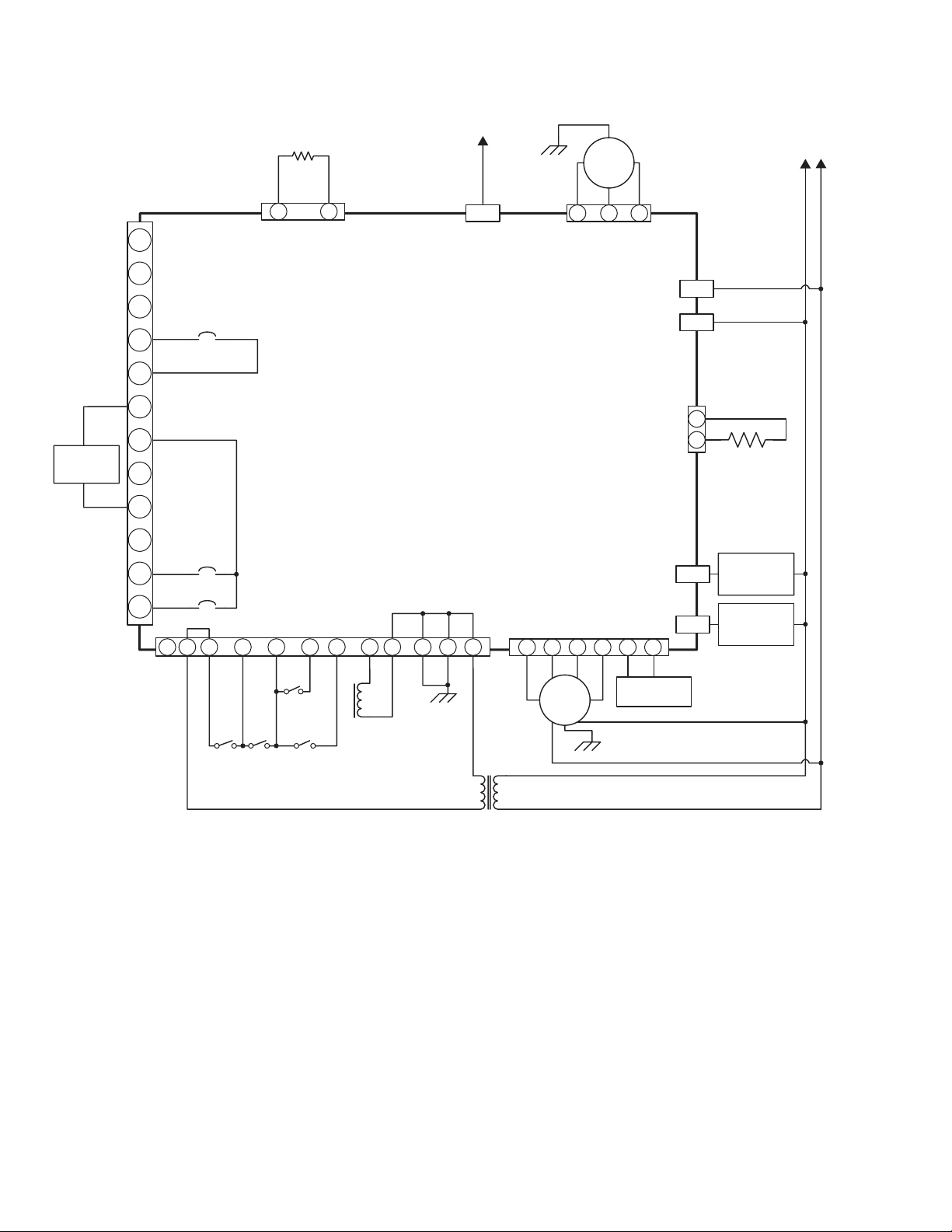
See Fig. 2 on page 6 for a typical wiring diagram.
3 69-2088—01
S9240F1004 MODULATING HOT SURFACE IGNITION INTEGRATED FURNACE CONTROL
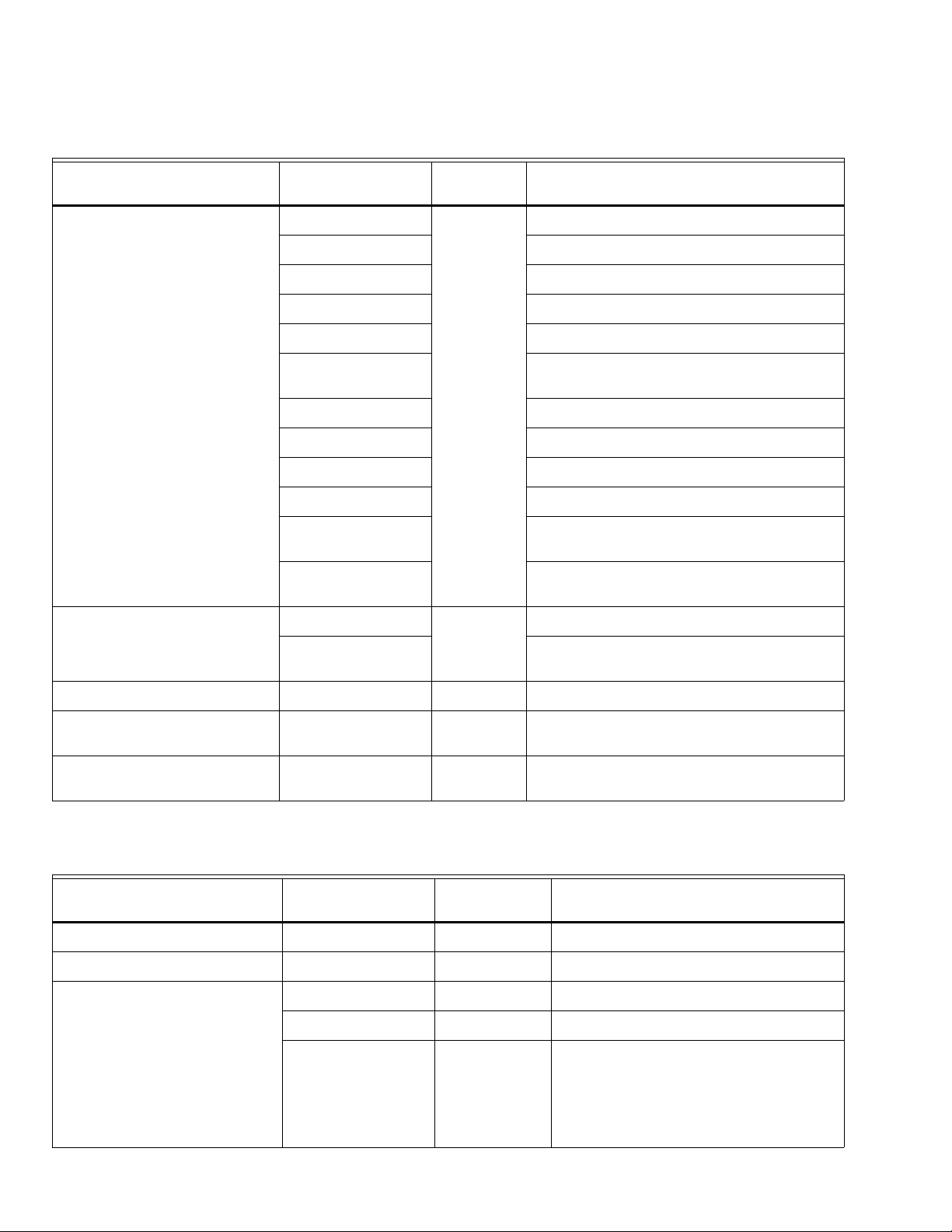
Table 1. Wiring Connections - Class 2 - Low Voltage.
Terminal Type Connection/Label
12-position screw terminal block
(#5 screw)
4-position screw terminal block
(#5 screw)
Board label
(see Fig. 1) Connects S9240F to:
W1
Thermostat 1st stage heat input
W2 Thermostat 2nd stage heat input
G Thermostat continuous fan input
Y2 Thermostat 2nd stage cool input
Y1 Thermostat 1st stage cool input
C 24 Volt ground (connected to transformer and
chassis ground)
R 24 Volt hot
E7
DH Not used
H - (optional) If used: 24V humidifier output
L Not used
O - (optional) If used: Thermostat signal to heat pump
reversing valve input
DS - (optional) If used: Thermostat Dehumidification or
Harmony Zoning input
Outdoor Sensor
Discharge Air Sensor
E4
Not used
If used: Discharge air sensor
- (optional)
Straight Spade Quick Connect Flame Sense E42 Flame signal input
12-pin connector (male terminals) Main Harness J2 Main valve, pressure switches, rollout, limit,
chassis ground, and 24 Vac
6-pin connector (male terminals) Circulator Motor P79 Motor serial control interface and furnace size
select input
Table 2. Wiring Connections - Class 1 - Line Voltage.
Board label
Terminal Type Connection/Label
(see Fig. 1) Connects S9240F to:
2 pin connector (male terminals) Igniter P77 – HSI Igniter interface
3-pin connector (male terminals) CAI Connector J3 – CAI 3-phase AC power
Straight Spade Quick-connect Humidifier HUM Humidifier 120 Vac output
EAC EAC Electronic air cleaner 120 Vac output
Neutrals E36, E37,
E38, E39,
and E40
Any neutral connector can be used for:
• 120 Vac Input neutral
• Transformer neutral
• Electronic air cleaner neutral
• Circulator neutral
• Humidifier neutral
69-2088—01 4

S9240F1004 MODULATING HOT SURFACE IGNITION INTEGRATED FURNACE CONTROL
.
Table 3. Jumpers.
Jumper
(see Fig. 1) Action:
W915 - 2-Stage Compressor W915 UNCUT: Single stage compressor (factory default)
CUT: 2-stage compressor
W951 - Heat Pump W951 UNCUT: Compressor heating disabled (factory default)
CUT: Compressor heating enabled
W914 - Dehumidifier or Harmony III W914 UNCUT: Harmony III and dehumidifying operation disabled
(factory default)
CUT: Harmony III and dehumidifying operation enabled
Board label
SIDE HOOK (X2)
PANEL MOUNTING
FOR
W1
W2
G
Y2
E7
Y1
C
R
DH
50029412-001 Rev. A
H
L
TEMPERATURE SENSORS – E4
OUTDOOR
EQUIPMENT
RCI –I +
INDOOR
EQUIPMENT
RCI –I +
W1 W2 G Y2 Y1 DH H O DSC
LR
W914
DEHUM
OR
HARMONY
W951
HEAT
PUMP
COMPR
2 STAGE
I –
W915
I+
P80
SELECTION
CUT FOR
OPTION
3
6
9
12
1
S3
AIR SENSOR
DISCHARGE
15 17
19
1
4
7
10
SENSOR
OUTDOOR
1614 18
S2 S1 PUSH BUTTON E42 – FLAME SENSE
LED
ON ON
3
6
ON
8
10
119
12
13
1234567
R
EAC HUM
1
4
R
L1
SENSE
FLAME
3
1
HSI
2
J3 – CAI
1
NEUTRALS
W914
DEHUM
OR
HARMONY
W951
HEAT
PUMP
W915
2-STAGE
COMPR
J2
MAIN
HARNESS
P79
CIRCULATOR
MOTOR
HARNESS
HUMEAC
L1
P77
HSI
NEUTRALS
E36, E37, E38, E39, AND E40
FACTORY USE ONLY.1
Fig. 1. Typical wiring connections and component locations for S9240F1004 Integrated Furnace Control
(minor components removed for clarity).
5 69-2088—01
M28148
S9240F1004 MODULATING HOT SURFACE IGNITION INTEGRATED FURNACE CONTROL
24V
HUMIDIFIER
(OPTIONAL)
W1
W2
Y2
Y1
DH
DS
DISCHARGE AIR SENSOR
(OPTIONAL)
21
E4
G
W915
C
E7
R
H
L
O
W951
W914
3511 6 1218472109
J2
FLAME ROD
FLAME SENSE
P79
312 4
3 PHASE COMBUSTION
AIR INDUCER
M
213
J3
P77
56
L1
L2
1
2
HUM
EAC
95V HSI
LINE VOLTAGE
HUMIDIFIER
(OPTIONAL)
ELECTRONIC
AIR CLEANER
(OPTIONAL)
120 V / 60 HZ
AC MAINS
L2 L1
FURNACE SIZE
IDENTIFIER
ROLLOUT
SWITCH
HIGH
LIMIT
SWITCH
HIGH
PRESSURE
SWITCH
LOW
PRESSURE
SWITCH
MAIN
VALV E
24 VAC
REGAL
BELOIT
ECM 3.0
INDOOR
AIR BLOWER
M
Fig. 2. Typical wiring diagram for S9240F1004 Integrated Furnace Control.
M28147
69-2088—01 6
S9240F1004 MODULATING HOT SURFACE IGNITION INTEGRATED FURNACE CONTROL
SETTINGS AND ADJUSTMENTS
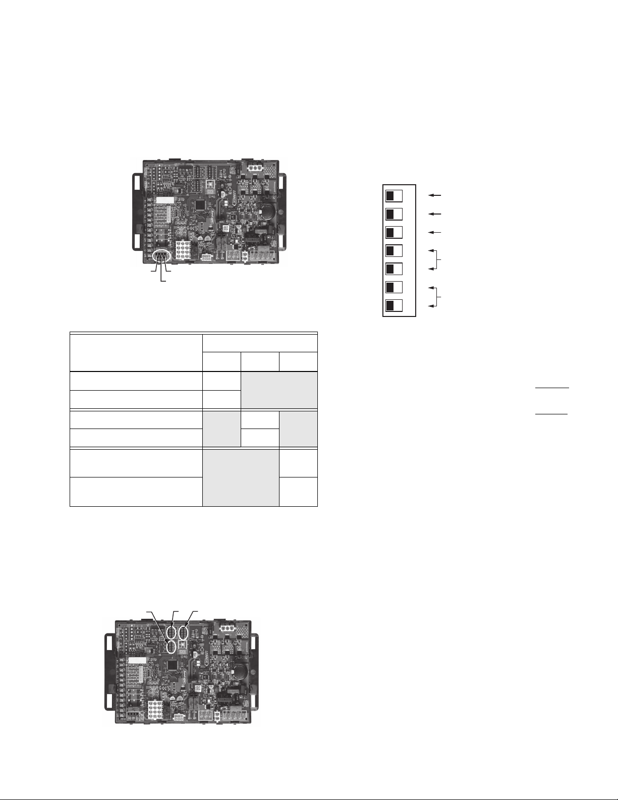
Jumpers
Three jumpers are located on the S9240 board. The jumpers
are all ON (uncut) from the factory. To change any jumper, first
disconnect the power, then cut the desired jumper.
W915 - 2 STAGE COMPRW914 - DEHUM/HARMONY
W951 - HEAT PUMP
Fig. 3. Jumper locations.
Table 4. Jumper Conditions - Defaults in Bold.
Jumper
Description
W915 W951 W914
Single stage compressor Uncut
2-stage compressor Cut
Disable compressor heating
Uncut
Enable compressor heating Cut
M28149
DIP Switch S1 Settings
Five parameters may be set with this 7-position DIP switch.
Refer to Fig. 4 for location of DIP switch S1.
The default factory settings (all OFF) are shown in Fig. 5 and
indicated in Bold in Table 5 on page 8.
To change any setting, first disconnect the power, then set
SW1 through SW7 according to Table 5 on page 8.
.
DIP SWITCH S1
Fig. 5. DIP Switch S1 - shown with factory default
SW1: STAGE SELECTION
The stage selection is factory-set (OFF) to a 2-stage
thermostat with the 2nd and 3rd stage On Delays disabled
The ON position configures the IFC for a single stage
thermostat with the 2nd and 3rd stage On Delays enabled
NOTE: Selection of the single stage position (ON) allows
three stage operation with a single stage thermostat.
ON
12 43576
SINGLE OR 2-STAGE THERMOSTAT
SELECTION
CONVENTIONAL 2-STAGE OR
LENNOX MODULATING SEQUENCE
2ND STAGE ON DELAY
HEAT FAN OFF DELAY
FAN SPEED - THERMOSTAT “G”
settings; all OFF.
M28151
.
.
Disable Harmony III and
Uncut
dehumidifying operation
Enable Harmony III and
Cut
dehumidifying operation
DIP Switches
There are three DIP switch blocks on the S9240F (see Fig. 4):
• S1 – see “DIP Switch S1 Settings”
• S2 – see “DIP Switch S2 Settings – Cooling Airflow” on
page 9.
• S3 – see “DIP Switch S3 Settings – Heating Airflow” on
page 10.
S3 S1
Fig. 4. DIP Switch locations (S1, S2, and S3).
S2
M28150
SW2: SEQUENCE
The sequence is factory-set (OFF) to respond to a thermostat
as dictated by the SW1 selection.
The ON position configures the IFC for the Lennox modulating
firing state sequence with 2-stage thermostat.
NOTE: SW2 position is ignored if SW1 is ON.
SW3: 2ND STAGE ON DELAY
The On Delay timing applies to systems configured only with
single stage thermostats. It is the length of time operating in
normal low fire mode before switching to high fire mode. The
timing is factory-set (OFF) to 7 minutes.
The ON position configures the 2nd stage On Delay for 12
minutes.
NOTE: SW3 position is ignored if SW1 is OFF.
SW4-5: HEAT FAN OFF DELAY
The Heat Fan Off Delay is the period between the loss of
supervised main burner flame after the call for heat has ended
and the deactivation of the blower motor at the low heat
speed. The timing is factory-set (all OFF) to 90 seconds. See
Table 5 on page 8 for other timing settings.
SW6-7: FAN SPEED – THERMOSTAT “G”
The fan speed is factory-set (all OFF) to Medium-low. See
Table 5 on page 8 for other speed settings.
7 69-2088—01
S9240F1004 MODULATING HOT SURFACE IGNITION INTEGRATED FURNACE CONTROL
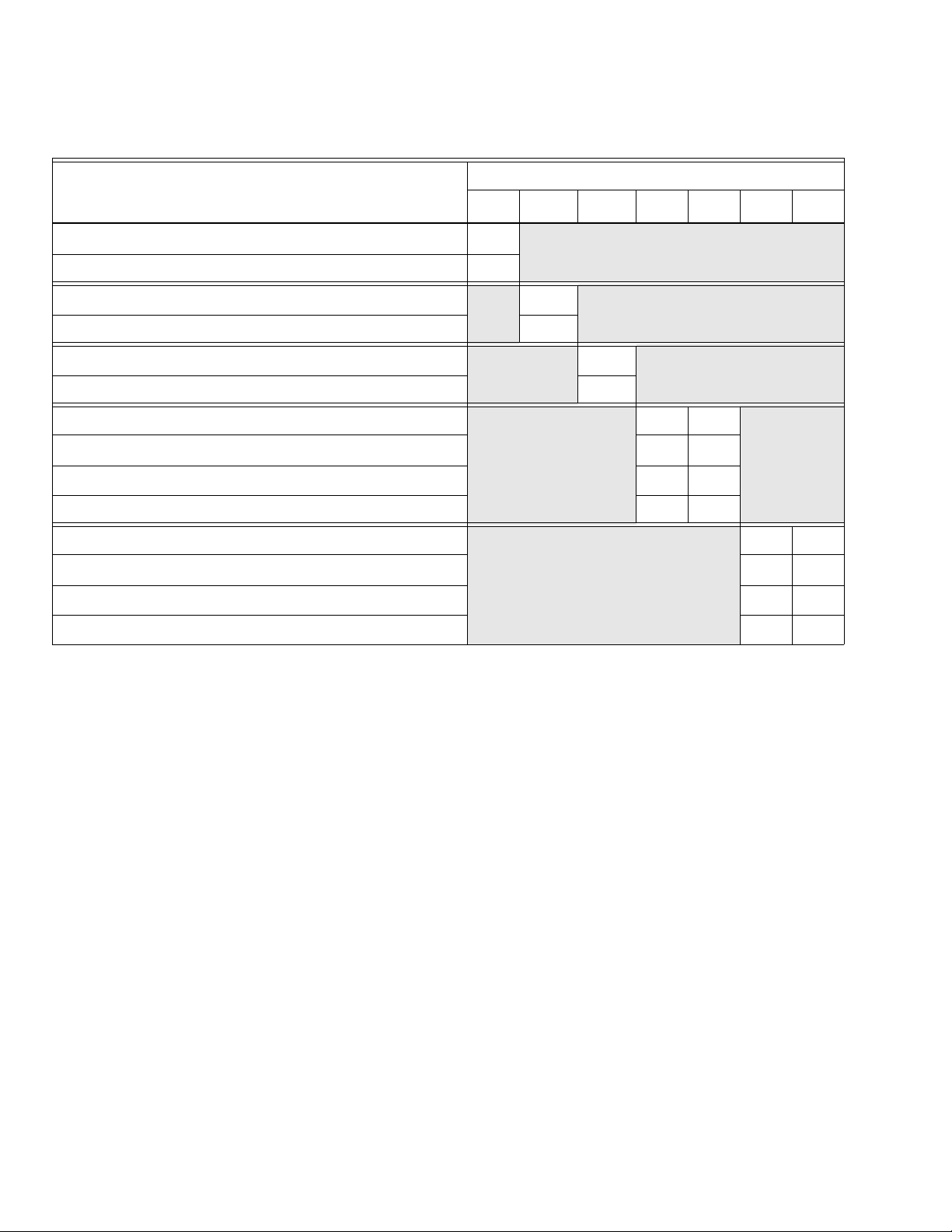
Table 5. DIP Switch S1 Settings - Defaults in Bold.
Individual Switches
a
Description
SW1 SW2
SW3bSW4 SW5 SW6 SW7
2-Stage Thermostat: 2nd and 3rd stage On Delay disabled
OFF
Single Stage Thermostat: 2nd and 3rd stage On Delay enabled ON
Conventional 2-stage sequence with 2-stage thermostat
OFF
Lennox modulating sequence with 2-stage thermostat ON
2nd Stage On Delay - 7 minutes
OFF
2nd Stage On Delay - 12 minutes ON
Heat Fan Off Delay - 60 seconds
Heat Fan Off Delay - 90 seconds
OFF ON
OFF OFF
Heat Fan Off Delay - 120 seconds ON OFF
Heat Fan Off Delay - 180 seconds ON ON
Low fan speed (fan only operation)
Medium-low fan speed (fan only operation)
OFF ON
OFF OFF
Medium-high fan speed (fan only operation) ON OFF
High fan speed (fan only operation) ON ON
a
Switch 2 is ignored if switch 1 is in the ON position.
b
Switch 3 is ignored if switch 1 is in the OFF position.
69-2088—01 8
S9240F1004 MODULATING HOT SURFACE IGNITION INTEGRATED FURNACE CONTROL
DIP Switch S2 Settings – Cooling Airflow
DIP Switch S2 is used to adjust the cooling speed and profile.
Refer to Fig. 4 on page 7 for location of DIP switch S2.
The default factory settings (all OFF) are shown in Fig. 6 and
indicated in Bold in Table 6.
To change any setting, first disconnect the power, then set
SW8 through SW13 according to Table 6.
.
Fig. 6. DIP Switch S2 - shown with factory default
DIP SWITCH S2
ON
89 1110 12 13
settings; all OFF.
COOL SPEED
COOL SPEED ADJUSTMENT
COOLING PROFILE
M28152
SW8-9: COOLING FAN SPEED
The fan speed during cooling is factory-set to High.
SW10-11: COOLING FAN SPEED ADJUSTMENT (CFM)
The fan CFM during cooling is factory-set to normal (Base
Tap).
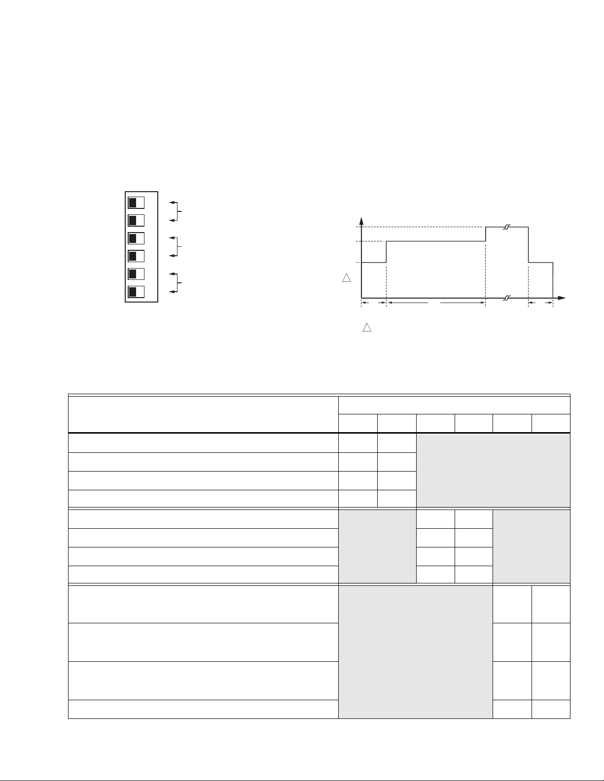
SW12-13: COOLING PROFILE
The fan profile during cooling is factory-set to 30 seconds at
50%, 7.5 minutes at 82%, run at 100%, and with a 30 second
Off delay at 50%. Fig. 7 illustrates the factory-set cooling
profile. The fan speed ramps up and down during speed
changes.
.
100%
F
A
82%
N
S
P
50%
E
E
1
D
30
FAN SPEED AS A PERCENT OF MAXIMUM.
1
450
TIME (SECONDS)
30
M28161
Fig. 7. Fan cooling speed ramp up and ramp down profile
(factory default shown).
Table 6. DIP Switch S2 Settings – Cooling Airflow.
Individual Switches
Description
High Cool Speed (circulator)
SW8 SW9 SW10 SW11 SW12 SW13
OFF OFF
Medium-low Cool Speed (circulator) OFF ON
Medium-high Cool Speed (circulator) ON OFF
Low Cool Speed (circulator) ON ON
Normal CFM - Base tap
OFF OFF
Decrease Cool speed CFM by 10% OFF ON
Increase Cool speed CFM 10% ON OFF
ECM Test Mode (motor slew rates disabled) ON ON
Cooling Profile -
On: 30 seconds at 50%, 7.5 minutes at 82%, then run at 100%
Off: 30 second Off Delay at 50%
Cooling Profile -
On: No On Delay (run at 100%)
Off: 60 second Off Delay at 100%
OFF OFF
OFF ON
Cooling Profile -
On: 7.5 minutes at 82%, then run at 100%
ON OFF
Off: no Off Delay
Cooling Profile - no On or Off Delays ON ON
9 69-2088—01
 Loading...