


SUPER TRADELIN
E
S8910U Universal Hot
Surface Ignition Module
®
INSTALLATION INSTRUCTIONS
Installation Instructions for the Trained Service Technician.
APPLICATION
The SUPER TRADELINE® S8910U Universal Hot
Surface Ignition Module is designed to provide easy field
replacement for a wide range of hot surface ignition
modules manufactured by Honeywell, Robertshaw and
White-Rodgers. The S8910U Module provides operating
control of a direct ignition system using a 120 Vac hot
surface igniter. The S8910U replaces existing flame
rectification type hot surface ignition modules with the
following characteristics:
• 120 Vac (up to 5A) timed warmup hot surface ignition
elements.
• Single rod (local sense) or dual rod (remote sense) hot
surface ignition.
• One or three ignition trials per call for heat.
• Four-second or seven-second ignition trials.
• Prepurge of 32 seconds or less.
• Up to 96 seconds between trial purge times (three-trial
mode only).
• Natural or LP gas.
The S8910U is
• Intermittent pilot ignition controls.
• Direct spark ignition controls.
• Proven 120 Vac hot surface ignition controls.
• 24 Vac element hot surface ignition controls.
• 240 Vac input/120 Vac element hot surface ignition
controls.
• 120 Vac timed warmup hot surface ignition controls
with:
—Ignition trial time shorter than four seconds.
—Ignition trial time longer than twelve seconds.
—Edge connectors rather than male quick-connects.
The SUPER TRADELINE® S8910U package contains the
S8910U control, and easy-to-use instructions, and the
accessories required to adapt the existing hot surface
ignition module. The accessory bag assembly includes the
White-Rodgers adapter, Robertshaw ground lead, four
1/4 in. female .032 quick-connects, one 3/16 in. female
.032 quick-connect, four selection tabs and seven wire
labels. The wiring labels are included to assure proper
marking of the wires attached to the existing module.
A complete list of the specific Honeywell and other
modules that the SUPER TRADELINE
designed to replace is provided in Tables 1 through 3.
not
designed to replace:
®
S8910U is
NOTE: The S8910U is intended to replace only defective
ignition controls. The service technician should
make sure that the other parts of the appliance
and control system operate safely and reliably
before replacing the ignition control.
WARNING
EXPLOSION HAZARD. CAN CAUSE
INJURY OR EQUIPMENT DAMAGE.
The S8910U can only be used for direct replacement. Check Tables 1 through 3 before replacing
an existing hot surface module with the S8910U. If
the existing module is not listed, do not use the
S8910U to replace it. Always use the selection tab
specified in Tables 1 through 3 for the existing
module being replaced. Replacing with an unlisted
module or using a selection tab not specified can
result in appliance malfunction.
Electrical Ratings:
Control Voltage: 24V, 60 Hz.
Maximum Valve Contact Rating: 2A.
Current Draw: .4A plus valve load.
Hot Surface Igniter Voltage: 120 Vac, 60 Hz.
Contact Rating At 120 Vac: 5A.
IMPORTANT
Use the S8910U only in a 60 Hz system. Be sure
the system is not 50 Hz.
Hot Surface Igniter or Igniter-Sensor:
Norton Model 201 or 271 or equivalent.
NOTE: If an igniter other than a Norton Model 201 or 271
is used, the igniter must meet the following
minimum specifications required over the life of
the igniter:
• Igniter must reach 1832°F (1000°C) within
34 seconds with 102 Vac applied.
• Igniter must maintain at least 500M ohms
insulation resistance between the igniter
leadwires and the igniter mounting bracket.
• Igniter must not develop an insulating layer
on its surface (over time) that would prevent
flame sensing.
• Igniter surface area immersed in flame must
not exceed one-fourth of the grounded area
immersed in flame. This would prevent flame
sensing.
• Igniter current draw at 132 Vac must not
exceed 5A.
®U.S. Registered Trademark
Copyright © 1996 Honeywell Inc. • All Rights Reserved
X-XX UL
69-0845-2
S8910U UNIVERSAL HOT SURFACE IGNITION MODULE
Sensor:
A separate sensor is required for remote sensing applications.
Wiring:
Use the existing appliance wiring. If repair or replacement
of leadwires is required, follow the instructions on the
appliance label. Use the included quick-connect terminals
according to the instructions.
Prepurge:
32 seconds.
Igniter Warmup:
34 seconds.
Between Trial Purge:
96 seconds (three trial mode only).
Flame Failure Response Time:
1.5 seconds maximum.
Ignition Sequence:
The number of trials for ignition and trial time are determined by the selection tab. See Table 1. If a selection tab
is not installed, the module will operate at four seconds
trial time and one ignition trial.
Ambient Operating Temperature:
-40°F to +175°F (-40°C to +79°C).
Accessory Bag Assembly:
• White-Rodgers adapter.
• Robertshaw ground lead.
• Four 1/4 in. female .032 quick-connects.
• One 3/16 in. female .032 quick-connect.
• Four selection tabs.
• Seven wire labels.
Approval Bodies:
IAS Design Certified: Certification Report No. C2027002.
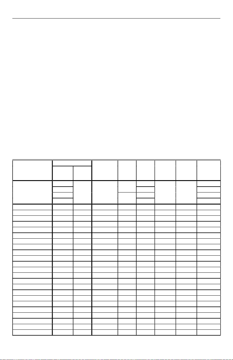
Table 1. White-Rodgers Control to Honeywell S8910U Cross Reference.
NOTES: This list is for reference only. Honeywell reserves the right to add or delete models at any time, based on new or
updated information.
White-Rodgers product information was obtained from the 1991 White-Rodgers Product Catalog (R3700).
S8910U
Model
Numbers
S8910U
Specifications
Tab
Remove
Jumper
Selection
A—
B
Black
Local (L) or
Remote (R)
Sensing
Local or
Remote
Lockout
Time
(sec)
Ignition
Trials
PrePurge
(sec)
Igniter
Warmup
(sec)
4 1 32 34 NA
396
Between
Trial Purge
(sec)
C71NA
D396
50E47-1 thru 9 A Yes R 4 1 0 17 NA
50E47-10 thru 19 A Yes R 4 1 0 45 NA
50E47-20 thru 29 A Yes R 4 1 30 17 NA
50E47-30 thru 39 A Yes R 4 1 30 45 NA
50E47-40 thru 49 B Yes R 4 3 30 17 90
50E47-50 thru 59 B Yes R 4 3 30 45 90
50E47-60 thru 69 B Yes R 4 3 0 17 60
50E47-70 thru 79 B Yes R 4 3 0 45 60
50E47-101 thru 109 C Yes R 7 1 0 17 NA
50E47-110 thru 119 C Yes R 7 1 0 45 NA
50E47-120 thru 129 C Yes R 7 1 30 17 NA
50E47-130 thru 139 C Yes R 7 1 30 45 NA
50E47-140 thru 149 D Yes R 7 3 30 17 90
50E47-150 thru 159 D Yes R 7 3 30 45 90
50E47-160 thru 169 D Yes R 7 3 0 17 60
50E47-170 thru 179 D Yes R 7 3 0 45 60
50E47-201 thru 209 A Yes R 4 1 0 17 NA
50E47-210 thru 219 A Yes R 4 1 0 45 NA
50E47-220 thru 229 A Yes R 4 1 30 17 NA
50E47-230 thru 239 A Yes R 4 1 30 45 NA
50E47-240 thru 249 B Yes R 4 3 30 17 90
50E47-250 thru 259 B Yes R 4 3 30 45 90
50E47-260 thru 269 B Yes R 4 3 0 17 60
continued
69-0845—2
2
S8910U UNIVERSAL HOT SURFACE IGNITION MODULE
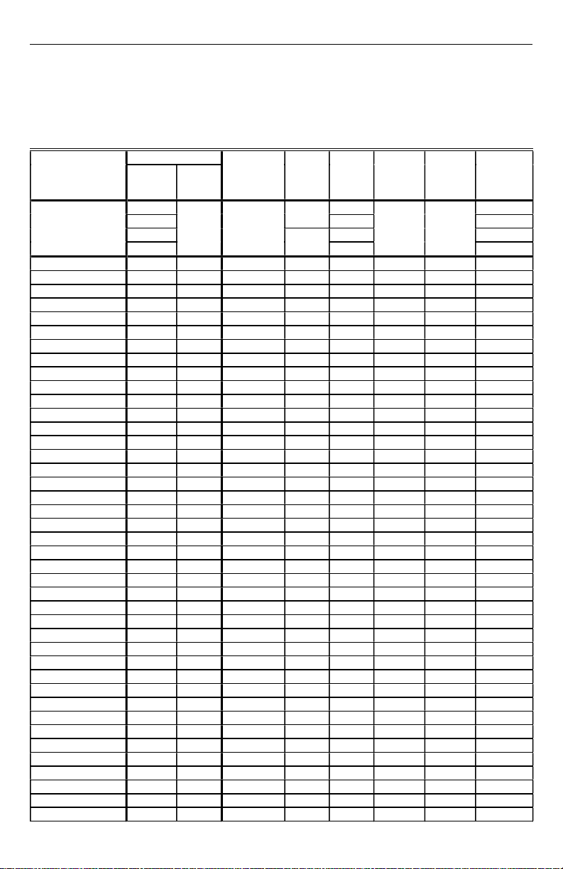
Table 1. White-Rodgers Control to Honeywell S8910U Cross Reference (Continued).
NOTES: This list is for reference only. Honeywell reserves the right to add or delete models at any time, based on new or
updated information.
White-Rodgers product information was obtained from the 1991 White-Rodgers Product Catalog (R3700).
S8910U
Model
Numbers
S8910U
Specifications
Tab
Remove
Jumper
Selection
A—
B
Black
Local (L) or
Remote (R)
Sensing
Local or
Remote
Lockout
Time
(sec)
Ignition
Trials
PrePurge
(sec)
Igniter
Warmup
(sec)
4 1 32 34 NA
396
Between
Trial Purge
(sec)
C71NA
D396
50E47-270 thru 279 B Yes R 4 3 0 45 60
50E47-301 thru 309 C Yes R 7 1 0 17 NA
50E47-310 thru 319 C Yes R 7 1 0 45 NA
50E47-320 thru 329 C Yes R 7 1 30 17 NA
50E47-330 thru 339 C Yes R 7 1 30 45 NA
50E47-340 thru 349 D Yes R 7 3 30 17 90
50E47-350 thru 359 D Yes R 7 3 30 45 90
50E47-360 thru 369 D Yes R 7 3 0 17 60
50E47-370 thru 379 D Yes R 7 3 0 45 60
50F47-1 thru 9 A Yes R 4 1 0 17 NA
50F47-10 thru 19 A Yes R 4 1 0 45 NA
50F47-20 thru 29 A Yes R 4 1 17 17 NA
50F47-30 thru 39 A Yes R 4 1 17 45 NA
50F47-40 thru 49 B Yes R 4 3 17 17 77
50F47-50 thru 59 B Yes R 4 3 17 45 77
50F47-60 thru 69 B Yes R 4 3 0 17 60
50F47-70 thru 79 B Yes R 4 3 0 45 60
50F47-101 thru 109 C Yes R 7 1 0 17 NA
50F47-110 thru 119 C Yes R 7 1 0 45 NA
50F47-120 thru 129 C Yes R 7 1 17 17 NA
50F47-130 thru 139 C Yes R 7 1 17 45 NA
50F47-140 thru 149 D Yes R 7 3 17 17 77
50F47-150 thru 159 D Yes R 7 3 17 45 77
50F47-160 thru 169 D Yes R 7 3 0 17 60
50F47-170 thru 179 D Yes R 7 3 0 45 60
50F47-201 thru 209 A Yes R 4 1 0 17 NA
50F47-210 thru 219 A Yes R 4 1 0 45 NA
50F47-220 thru 229 A Yes R 4 1 17 17 NA
50F47-230 thru 239 A Yes R 4 1 17 45 NA
50F47-240 thru 249 B Yes R 4 3 17 17 77
50F47-250 thru 259 B Yes R 4 3 17 45 77
50F47-260 thru 269 B Yes R 4 3 0 17 60
50F47-270 thru 279 B Yes R 4 3 0 45 60
50F47-301 thru 309 C Yes R 7 1 0 17 NA
50F47-310 thru 319 C Yes R 7 1 0 45 NA
50F47-320 thru 329 C Yes R 7 1 17 17 NA
50F47-330 thru 339 C Yes R 7 1 17 45 NA
50F47-340 thru 349 D Yes R 7 3 17 17 77
50F47-350 thru 359 D Yes R 7 3 17 45 77
50F47-360 thru 369 D Yes R 7 3 0 17 60
50F47-370 thru 379 D Yes R 7 3 0 45 60
3
69-0845—2
S8910U UNIVERSAL HOT SURFACE IGNITION MODULE
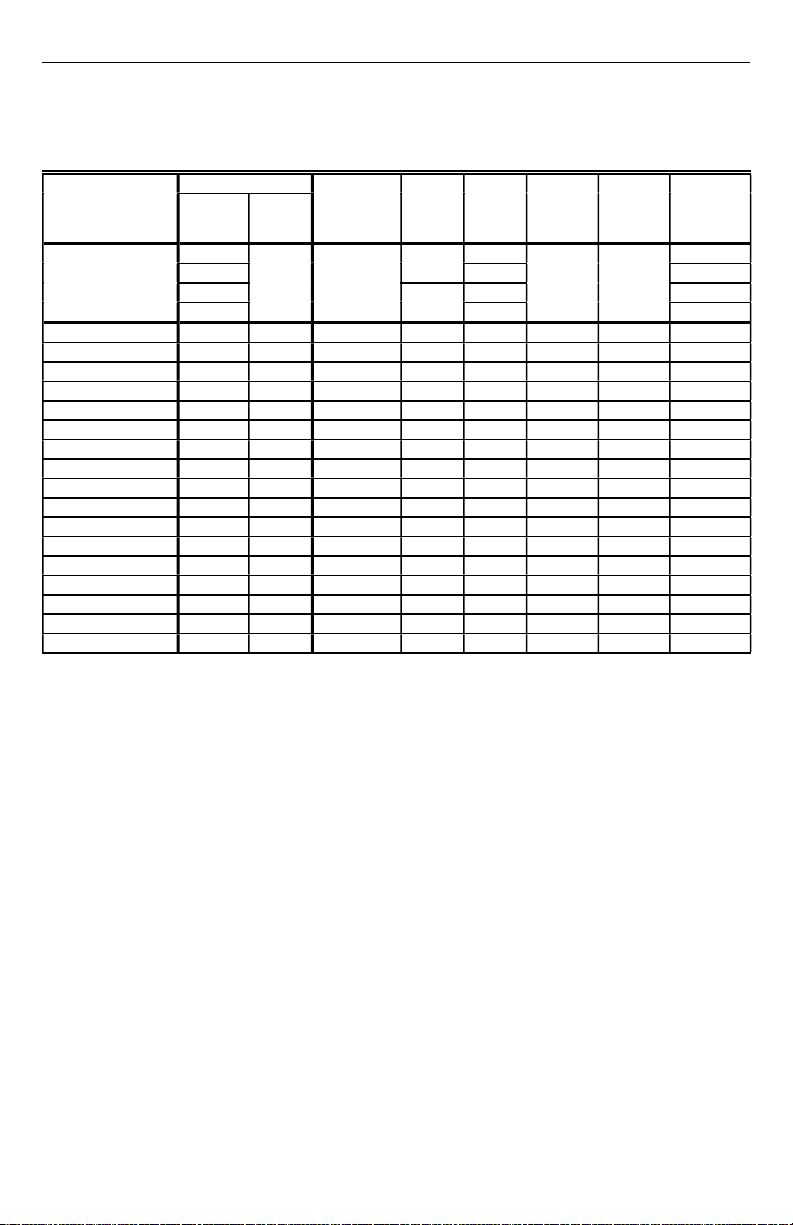
Table 2. Robertshaw Control to Honeywell S8910U Cross Reference.
NOTE: Robertshaw product information was obtained from the 1993-1994 Robertshaw Uni-Line Catalog (2–064).
S8910U
Model
Numbers
S8910U
Specifications
Selection
Remove
Tab
Jumper
A—
B
C71NA
D396
HS780-17NL-104A A No L 4 1 0 17 NA
HS780-17NL-108A C No L 8
HS780-17NL-304A B No L 4 3 0 17 17
HS780-17NL-308A D No L 8
HS780-17NR-104A A Yes R 4 1 0 17 NA
HS780-17NR-306A D Yes R 6
HS780-17NR-308A D Yes R 8
HS780-34NL-108A C No L 8
HS780-34NL-304A B No L 4 3 0 34 34
HS780-34NL-306A D No L 6
HS780-34NL-308A D No L 8
HS780-34NL-312A D No L 12
HS780-34NR-104A A Yes R 4 1 0 34 NA
HS780-34NR-306A D Yes R 6
HS780-34NR-308A D Yes R 8
HS780-34NR-312A D Yes R 12
HS780-34PL-308A D No L 8
a
The S8910U and the original control lockout times are different. The S8910U lockout time is within the design tolerance
lockout time of the original control.
b
The lockout time of the S8910U is shorter than the original control. Be sure to observe the appliance operation under a
variety of input conditions to assure reliable operation.
Black
Local (L) or
Remote (R)
Sensing
Local or
Remote
Lockout
Time
(sec)
Ignition
Trials
PrePurge
(sec)
Igniter
Warmup
(sec)
4 1 32 34 NA
396
a
1017NA
a
3 0 17 17
a
3 0 17 17
a
3 0 17 17
a
1034NA
a
3 0 34 34
a
3 0 34 34
b
3 0 34 34
a
3 0 34 34
a
3 0 34 34
b
3 0 34 34
a
33434 34
Between
Trial Purge
(sec)
69-0845—2
4
S8910U UNIVERSAL HOT SURFACE IGNITION MODULE
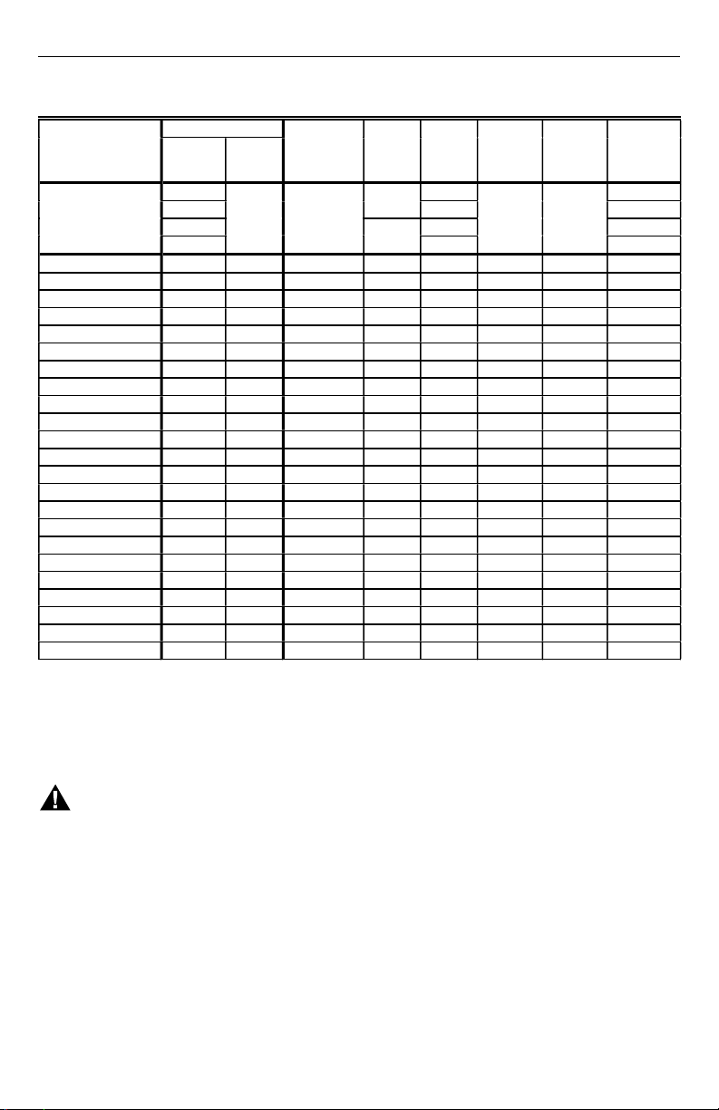
Table 3. Honeywell Control to Honeywell S8910U Cross Reference.
S8910U
Model
Numbers
S8910U
Specifications
S89C1004 C No L 6
S89C1012 C No L 6
S89C1046 A No L 4 1 0 34 NA
S89C1087 C No L 6
S89C1103 A No L 4 1 0 34 NA
S89D1002 C Yes R 6
S89G1005 B No L 4 3 0 34 30
S89G1013 D No L 6
S89G1021 D No L 11
S89G1047 D No L 6
S89H1003 B Yes R 4 3 0 34 30
S89H1011 D Yes R 6
S89H1029 D Yes R 11
S89J1008 C No L 6
S890C1007 C No L 6
S890D1006 C Yes R 6
S890G1003 B No L 4 3 30 34 30
S890G1011 D No L 6
S890G1029 D No L 11
S890G1037 D No L 6
S890H1002 B Yes R 4 3 30 34 30
S890H1010 D Yes R 6
S890H1028 D Yes R 11
a
The S8910U and the original control lockout times are different. The S8910U lockout time is within the design tolerance
lockout time of the original control.
b
The lockout time of the S8910U is shorter than the original control. Be sure to observe the appliance operation under a
variety of input conditions to assure reliable operation.
Selection
Remove
Tab
Jumper
A—
B
C71NA
D396
Black
Local (L) or
Remote (R)
Sensing
Local or
Remote
Lockout
Time
Ignition
(sec)
4 1 32 34 NA
a
a
a
a
a
b
a
a
b
a
a
a
a
b
a
a
b
PrePurge
Trials
(sec)
396
1034NA
1034NA
1034NA
1034NA
3 0 34 30
3 0 34 30
3 0 34 30
3 0 34 30
3 0 34 30
1034NA
13034NA
13034NA
33034 30
33034 30
33034 30
33034 30
33034 30
Igniter
Warmup
(sec)
Between
Trial Purge
(sec)
REVIEW THE INSTALLATION
WARNING
FIRE OR EXPLOSION HAZARD.
CAN CAUSE PROPERTY DAMAGE,
SEVERE INJURY, OR DEATH.
Follow these warnings exactly:
1. Review the installation as outlined in this
section.
2. Plan for frequent maintenance as described in
the Maintenance section.
When hot surface ignition systems are used on central
heating equipment in barns, greenhouses, and commercial
properties and on heating appliances such as commercial
cookers, agricultural equipment, industrial heating
equipment and pool heaters, heavy demands are made on
the controls. Special steps can be required to prevent
nuisance shutdowns and control failure due to frequent
cycling, severe environmental conditions related to
moisture, corrosive chemicals, dust or excessive heat.
These applications require Honeywell Home and Building
Control Engineering review; contact your Honeywell Sales
Representative for assistance.
Review the following conditions that can apply to your
specific installation and take the precautionary steps
suggested.
Frequent Cycling
These controls are designed for use on appliances that
typically cycle only three to four times an hour during the
heating season. In year-round applications with greater
cycling rates, the control can wear out more quickly.
Perform a monthly checkout.
Water or Steam Cleaning
If a module or gas control gets wet, replace it. If the
appliance is likely to be cleaned with water or steam, cover
the controls and wiring to protect from water or steam flow.
5
69-0845—2
 Loading...