

Honeywell S8700, S8700B, S8700D, S8700E, S8700F Installation Instructions Manual
...
9
9
S8700B,D-F,J-M Direct Spark
Ignition Controls
INSTALLATION INSTRUCTIONS
APPLICATION
S8700 Direct Spark Ignition Controls are designed for
use in a wide range of gas-fired appliance applicat ion s
that require direct main burner ignition and flame safety
control of gas burners. The S8700 is used to ignite the
main burner, sense the flame and control the gas valve.
See Table 1 for the model that best meets your
application needs.
The S8700B,E,J,L models provide sin gle r od flame
sensing (i.e., the spark rod also acts as the flame sense
rod). The S8700D,F,K,M models provide dual rod flame
sensing (i.e., the spark rod and flame rod are separate).
The S8700J,K,L,M models provide 30-second minimum
time delay between application of 24V power to the
control and initiation of the trial for ignition period for
applications that require prepurge. Al l m odel s have an
LED status indicator.
Table 1. S8700 Models.
Model
S8700B 1-rod local 1 0
S8700D 2-rod remote 1 0
S8700E 1-rod local 3 0
S8700F 2-rod remote 3 0
S8700J 1-rod local 1 30 minimum
S8700K 2-rod remote 1 30 minimum
S8700L 1-rod local 3 30 minimum
S8700M 2-rod remote 3 30 minimum
Flame
Sense
Trials for
Ignition
Prepurge
(seconds)
SPECIFICATIONS
Electrical
Input Voltage: 24 Vac (20.5 Vac minimum to 28.5 Vac
maximum) at 60 Hz.
Current Draw: 0.15A maximum in run mode at 24 Vac.
Thermostat Anticipator Setting: 0.15A plus actual v alve load.
Valve Output: 2.0A maximum run; 6.0A maximum
inrush at 24 Vac.
Alarm Output: 0.5A maximum resistive loa d (Out put is
positive phase, one-half wave rectified, 24 Vac).
Spark Output: 14 KV minimum into 25 picofar ad
capacitive load.
Environmental
Ambient Operating Temperature: -40°F to +175°F
(-40°C to +79°C).
Relative Humidity: 5% to 95% at 95°F (35°C ) ,
noncondensing.
Ignition Sequence/Flame Sense
Prepurge: See Table 1.
Ignition Trials to Lockout: See Table 1.
Trial for Ignition Times: 4.6, 6.6, 11.1 or 21.1 second
nominal available.
Between Trial Purge: 30 second minimum
(S8700E,F,L,M only).
Auto Reset from Lockout: 60 minutes minimum
(S8700E,F,L,M only).
Flame Failure Re-ignition Time: 0.8 second maximum
at 1 microamp flame current.
Flame Current:
Minimum Threshold: 1 microamp.
Appliance Application: 2.5 microamp mini m um reco m-
mended under all appliance operating conditions.
Approvals:
CSA International Design Certi fi ed to ANS I Z21.20,
Report Number C2030026.
PLANNING THE INSTALLATION
WARNING
Fire or Explosion Hazard.
Gas leaks can cause property da m age,
severe injury or death.
Follow these warnings exactly:
Plan the installation using the following out li ne.
Plan for frequent maintenance as described in
the Maintenance section.
Review the following conditions that apply to your
specific installation and take the precautionar y step s
suggested.
® U.S. Registered Trademark
Copyright © 2000 Honeywell Inc. • All Rights Reserved
69- 12
S8700B,D-F,J-M DIRECT SPARK IGNITION CONTROLS
Frequent Cycling
The S8700 is designed to cycle three to four times each
hour during the heating season. Year-round applications and applications with more frequent cycling ra tes
can wear out the controls more quickly than normal
operation. Perform monthly system checks to make
sure the system operates properly.
Water or Steam Cleaning
If a control gets wet, replace it. If the appliance is likely
to be cleaned with water or steam, cover the control and
wiring to protect them from water or steam flow. Mount
the control high enough above the floor so it does not
get wet during normal cleaning procedures.
High Humidity or Dripping Water
Dripping water can cause the control to fail. Never
install an appliance where water can drip on the control.
In addition, high ambient humidity can cause the control
to corrode and fail. If the appliance is in a humid atmosphere, make sure air circulation around the control is
adequate to prevent condensation. Also, regul ar ly
check out the system.
IMPORTANT
Always install a splash cover to protect the
control from water damage.
Corrosive Chemicals
Corrosive chemicals can attack the control, eventual ly
causing a failure. If chemicals are used for routine
cleaning, avoid contact with the control. Where
chemicals are suspended in air, as in some industrial or
agricultural applications, protect the con trol with an
enclosure.
Dust or Grease Accumulation
Heavy accumulations of dust or grease can cause the
control to malfunction. Where dust or grease can be a
problem, provide covers for the control to limit
contamination.
INSTALLATION
When Installing this Product…
Read these instructions carefully. Failure to follow
1.
them could damage the product or cause a
hazardous condition.
Check the ratings given in the instructions and on
2.
the product to make sure it is suitable for your
application.
The installer must be a trained, experienced
3.
service technician.
After installation is complete, check out system
4.
operation.
WARNING
Fire or Explosion Hazard.
Gas leaks can cause property damage ,
severe injury or death
Always turn off gas supply before installing a
new gas control.
Be sure to conduct a gas leak test after installing
the control.
CAUTION
Electric Shock Hazard.
Power supply can cause personal inj ur y or
equipmen t damage.
Disconnect power supply before installation.
IMPORTANT
If this is a replacement application, follo w th e
appliance manufacturer’s instructions, if
available.
The manufacturer usually provides wiri ng dia grams, start-up and checkout instructions and
service procedures for their system. If the
manufacturer’s instructions ar e not available,
use these instructions as a general guide.
Heat
Excessively high temperatures can damage the control.
Make sure the maximum ambient temperature at the
control does not exceed the rating of the control, see
Specifications section. If the appliance operates at very
high temperatures, use insulation, shielding and air
circulation, as necessary, to protect the control. Proper
insulation or shielding should be provided by the
appliance manufacturer; verify proper air circulation is
maintained when the appliance is installed.
System Requirements
S8700 system requirements:
— Q 347A Spark Igniter and Q354A Flame Sensor, or a
Q366 with separate spark igniter and flame sensor
mounted on a common bracket. (Equivalent ignit io n
hardware may be used.)
— Honeywell VR8205 Gas Valve (or equivalent)
designed for DSI applications. Valve loads must be
within the range listed in the Specifications section.
69-1299 2
MOUNTING
S8700 Control
Select a location within 6 ft (1.8m) of the burner that
permits a direct cable route to the spark igniter terminal.
Ready access to the S8700 terminals is necessary for
wiring and servicing. Do not exceed the ambient temperature rating given in the Specifications section.
To mount the S8700:
Mount the S8700 in any position. See Fig. 1 for
1.
mounting dimensions.
Use No. 6-32 machine screws or 1 in. No. 8 sheet
2.
metal screws for fastening.
Fasten the screws securely.
3.

13/16 (21)
2
(50)
1-1/8
(29)
2-13/16 (72)
3-15/16 (100)
3-3/8 (86)
3/16 (4)
5/17 (7)
3-3/8
(86)
7/8 (23)
M16233
5-3/16
(130)
Fig. 1. S8700 mounting dimensions in in. (mm).
Auxiliary Controls
Mount the spark igniter, flame sensor, temperature
control, transformer, gas control and any other auxiliary
controls according to the manufacturer’s instructions .
NOTE: NOTE: Make sure the 24V system transformer
is rated to handle both the S8700 current and
the total gas valve curren t.
WIRING
General Precautions
For circuits that differ from the diagrams in Fig. 2
1.
and 3, check the wiring diagrams from the heating
appliance manufacturer, if available. Carefully follow any special instructions that would affect the
following general procedures.
All wiring must comply with applicable elect ri cal
2.
codes and ordinances.
Disconnect the power supply before wiring to
3.
prevent electrical shock or equipment damage.
When installing a separate flame sensor, the
4.
sensor leadwire should be kept as short as
possible and should not be allowed to rest against
grounded metal surfaces.
gnition cable should not touch any metal surface
5. I
or current carrying wires. It must not be more than
6 ft (1.8m) long. See Table 2 for recommended
ignition cable.
Do not short valve terminals as this can damage
6.
the temperature controller, the transformer or the
S8700 control.
S8700B,D-F,J-M DIRECT SPARK IGNITION CONTROLS
Table 2. Recommended Ignition Cable.
Maximum
Ambient
Temperature
Rating
FC
Cable Type
RMS Voltage
Rating
UL Style 3257 10,000 482 250
Wiring the S8700 Control
Connect the system components to the S8700
1.
terminals as shown in the wiring diagrams, Fig. 2
and 3. Refer to the heating appliance manufacturer’s instructions for wiring any other auxiliar y
controls.
Adjust the temperature control heat anticipato r (if
2.
provided) to match the system current draw. The
current draw equals the total current requir ed for
the S8700 (0.15A) plus the gas valve and all other
24V control loads (vent dampers, and pre pur ge
relays). Gas valve must be designed for the DSI
application.
NOTE: NOTE: Use only recommended igni tion cable
(see Table 2), or equivalent, to connect the
S8700 with the spark igniter. Cable must not
run in continuous contact with a metal surface
or spark voltage is greatly reduced; use
ceramic standoff brackets if necessary. Cable
length must not exceed 6 ft (1.8m).
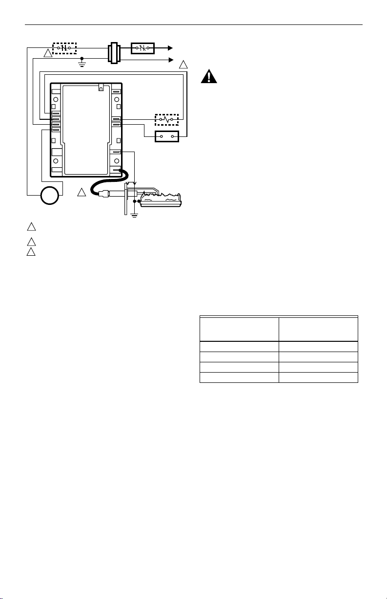
TRANSFORMER
FLAME
SENSE
ALARM
VALVE
(GND)
SPARK
3
LIMIT CONTROLLER
Q347
SPARK
IGNITER
IGNITER AND
BURNER GROUND
L1
(HOT)
L2
ALARM, IF USED
ANY COMBINATION
GAS CONTROL
2.0A MAX.
Q354 FLAME
SENSOR
BURNER
1
M16527
2
S8700D,F,K,M CONTROL
GND
VALVE (GND)
24 Vac (GND)
24 Vac
BURNER
TEMPERATURE
CONTOL
1
POWER SUPPLY. PROVIDE DISCONNECT MEANS AND OVERLOAD
PROTECTION AS REQUIRED.
2
ALTERNATE LIMIT CONTROLLER LOCATION.
3
MAXIMUM IGNITER-SENSOR CABLE LENGTH: 6 FT (1.8 M).
Fig. 2. Typical wiring diagram for
S8700D,F,K,M dual rod models.
3 69-1299
S8700B,D-F,J-M DIRECT SPARK IGNITION CONTROLS
L1
2
S8700E,J,L CONTROL
GND
VALVE (GND)
24 Vac (GND)
24 Vac
BURNER
(GND)
SPARK
3
TEMPERATURE
CONTOL
1
POWER SUPPLY. PROVIDE DISCONNECT MEANS
AND OVERLOAD PROTECTION AS REQUIRED.
2
ALTERNATE LIMIT CONTROLLER LOCATION.
3
MAXIMUM IGNITER-SENSOR CABLE LENGTH: 6 FT (1.8 M).
Fig. 3. Typical wiring diagram for
S8700E,J,L single rod models.
NOTE: NOTE: Proper system operation requires that
the S8700 GND (Burner) terminal is wired to
be electrically common with the spark
electrode bracket, flame sensor bracket (if a
separate flame sensor is used) and the main
burner. In many applications, this is
accomplished through connecting the S8 700
GND (Burner) terminal to the appliance
chassis, as the other noted components are
presumed to be electrically common with the
appliance chassis. If flam e sensing problems
are noted, it may be due to corroded or loose
electrical connections between the noted
components and the appliance chassis.
TRANSFORMER
FLAME
SENSE
ALARM
VALVE
LIMIT CONTROLLER
Q347
SPARK
IGNITER
IGNITER AND
BURNER GROUND
(HOT)
L2
ALARM, IF USED
ANY COMBINATION
GAS CONTROL
2.0A MAX.
BURNER
M16528
1
STARTUP
The following start-up procedures are basic to all S8700
controls. If this is a replacement application, refer to the
specific instructions provided by the heating appliance
manufacturer, if available. Also, since the auxiliary
controls used on any DSI system can differ, refer to the
manufacturer’s instructions for start-up and checkout
procedures for other system components.
NOTE: If the S8700 does not perform as outlined in
the following Start System and Check Trial for
Ignition steps, refer to the Service section to
determine the cause.
Gas Leak Test
If the gas control has been replaced as a part of the S8700
installation, perform the following test for gas leaks.
WARNING
Explosion or Fire Hazard.
Gas Leaks can cause property dam age,
severe injury or death.
To avoid possible explosion or fire, perform the
Gas Leak Test.
With the main burner in operation, paint the pipe joint s
and valve gasket with a rich soap and water solution.
Bubbles indicate a gas leak. To stop a leak, tighten the
joints and screws. Never use a flame to check for gas
leaks.
Start System
Turn on the power and the gas supply.
1.
Set the temperature control to call for heat and
2.
watch for a spark at the igniter (S8700B,D,E,F
models have no delay on start-up; S8700J,K,L,M
models have a predetermined delay on start- up
for prepurge).Check that the system starts as
follows: Prepurge delay (if provided), spark turns
on, gas valve opens at once and burner ignites
after gas reaches the main burner. Once the
burner flame is established, spark igniter cuts off.
NOTE: NOTE: If the gas control has been replaced or
serviced, lightoff may not be satisfactory until
air has been purged from the gas line or the
gas input and combustion air have been
adjusted (see manufacturer’s instru ctions).
Table 3. S8700 Trial for Ignition Periods.
Specified Trial for
Ignition (TFI) (stamped
on control)
4.6 sec 5.0 sec
6.6 sec 7.0 sec
11.1 sec 11.5 sec
21.1 sec 21.5 sec
Check Trial for Ignition
Check device label on the control to determine
1.
the correct trial for ignition time.
With the system power off and the thermostat or
2.
temperature control set to call for heat, manual ly
shut off the gas supply.
Turn power on to energize the S8700 and
3.
immedia t e l y start tim ing when the gas valve is
energized.
Determine the number of seconds to drop-out of
4.
the gas valve. It should not exceed the trial for
ignition time shown in Table 5.
After spark cutoff, manually reopen the gas sup-
5.
ply cock. No gas should flow to the main burner.
Reset the system as described in Resetting
6.
S8700 After Safety Lockout section.
Trial for Ignition Should
Not Exceed
69-1299 4
 Loading...