

Page 1
7800 SERIES
s
S7830
Expanded Annunciator
APPLICATION
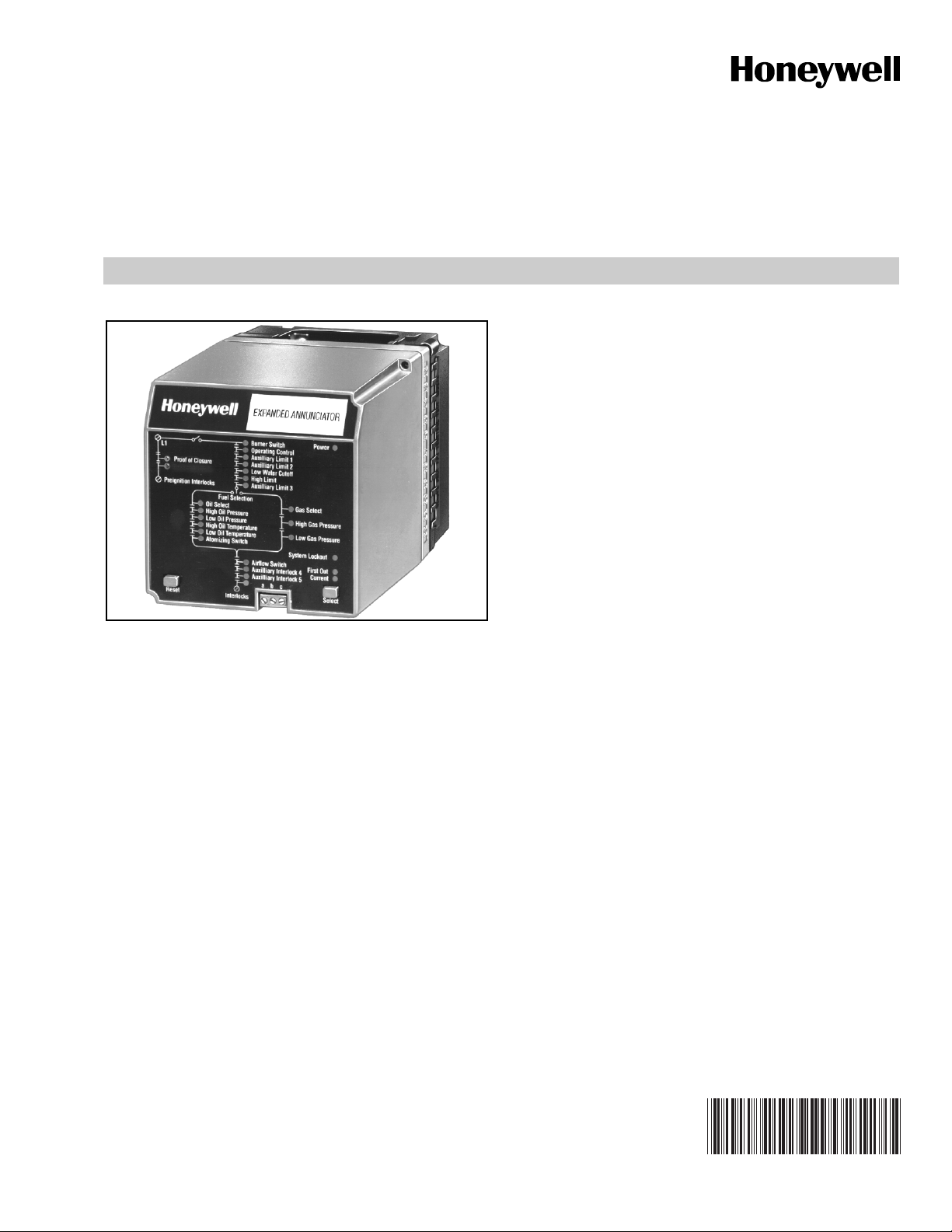
The S7830 Expanded Annunciator is an enhancement module
for use with 7800 SERIES Relay Modules. The S7830 is a
microprocessor-based device designed to monitor the status
of a series string of limit, control, and interlock contacts for a
commercial or industrial burner. The S7830 acts as a system
monitor and enhances fault and status messages of the 7800
SERIES burner control.
PRODUCT DATA
FEATURES
• 26 status light emitting diodes (LED).
• Front panel LED array, arranged in a pattern to clearly
indicate the flow of line voltage through the string of
limits, controls and interlocks.
• Selectable current and first-out LED array display
status.
• Power and proper operation indicating LED.
• Common Universal Mounting Subbase (Q7800A or B).
• 21 monitored contact points.
• Access for external electrical voltage checks.
• Communication interface capability.
• Capable of programmable limit or interlock messages
using the S7800A1142 Keyboard Display Module
(KDM).
• Open Lockout interlocks are indicated with a flashing
status LED when used with Relay Module Models with
Lockout Interlock feature.
• Hold messages displayed on the KDM are enhanced
with the Expanded Annuciator terminal description
information that is causing the hold (low water cutoff
for example).
• LED operational test.
• 36 additional 7800 SERIES fault and hold messages.
Content
pplication ........................................................................ 1
eatures ........................................................................... 1
pecifications ................................................................... 2
rdering Information ......................................................... 2
rincipal Technical Features ............................................ 4
nstallation ........................................................................ 4
iring ............................................................................... 5
peration ......................................................................... 9
65-0101-03
Page 2

7800 SERIES S7830 EXPANDED ANNUNCIATOR
SPECIFICATIONS
Electrical Ratings:
Voltage and Frequency: 120 Vac (+10%/-15%), 50/60 Hz
(±10%)
Power Dissipation: 4.6W maximum.
Terminal ratings: See Table 1.
.
Table 1. Terminal Ratings
Terminal Number Description
1
Earth Ground
a
b
Rating
—
2 Input Line Voltage (Neutral)
3 Input Line Voltage (Hot) 120 Vac, +10%/-15%.
4 Main Valve Proof of Closure 120 Vac, +10%/-15%, 2 mA.
5
6
7
Burner Switch
Operating Control
Auxiliary Limit # 1
b
b
b
8 Auxiliary Limit # 2
9
10
11
12
13
14
15
16
17
18
19
20
21
22
a
The S7830 must have an earth ground providing a connection between the subbase and the control panel or equipment. The earth
Low Water Cutoff
High Limit
Auxiliary Limit # 4
Oil Select Switch
High Oil Pressure
Low Oil Pressure
High Oil Temperature
Low Oil Temperature
Gas Select Switch
High Gas Pressure
Low Gas Pressure or Atomizing Switch
Air Flow Switch
Auxiliary Interlock # 4
Auxiliary Interlock # 5
b
b
b
b
b
b
b
b
b
b
b
b
b
b
ground must be capable of conducting the current to blow a 15A fuse (or breaker) in the event of an internal short circuit. the S7830
needs a low impedance ground connection to the equipment frame that, in turn, needs a low impedance connection to earth ground.
For a ground path to be low impedance at RF frequencies, the connection must be made with minimum length conductors that have
maximum surface areas. Wide straps or brackets, rather than leadwires, are preferred. Be careful to verify that the mechanically
tightened joints along the ground path, such as pipe or conduit threads or surfaces held together with fasteners, are free of
nonconductive coatings and are protected against mating surface corrosion.
b
The S7800A1142 Keyboard Display Module can change the default description.
ORDERING INFORMATION
When purchasing replacement and modernization products from your TRADELINE® wholesaler or distributor, refer to the
TRADELINE® Catalog or price sheets for complete ordering number.
If you have additional questions, need further information, or would like to comment on our products or services, please write or
phone:
1. Your local Honeywell Automation and Control Products Sales Office (check white pages of your phone directory).
2. Honeywell Customer Care
1885 Douglas Drive North
Minneapolis, Minnesota 55422-4386
In Canada—Honeywell Limited/Honeywell Limitée, 35 Dynamic Drive, Scarborough, Ontario M1V 4Z9.
International Sales and Service Offices in all principal cities of the world. Manufacturing in Australia, Canada, Finland, France,
Germany, Japan, Mexico, Netherlands, Spain, Taiwan, United Kingdom, U.S.A.
65-0101—03 2
Page 3
7800 SERIES S7830 EXPANDED ANNUNCIATOR
Environmental Ratings:\
Ambient Temperature Range:
Operating: -40°F to +140°F (-40°C to +60°C).
Storage: -40°F to +150°F (-40°C to +66°C).
Humidity: 85% continuous, noncondensing.
Vibration: 0.5 G environment.
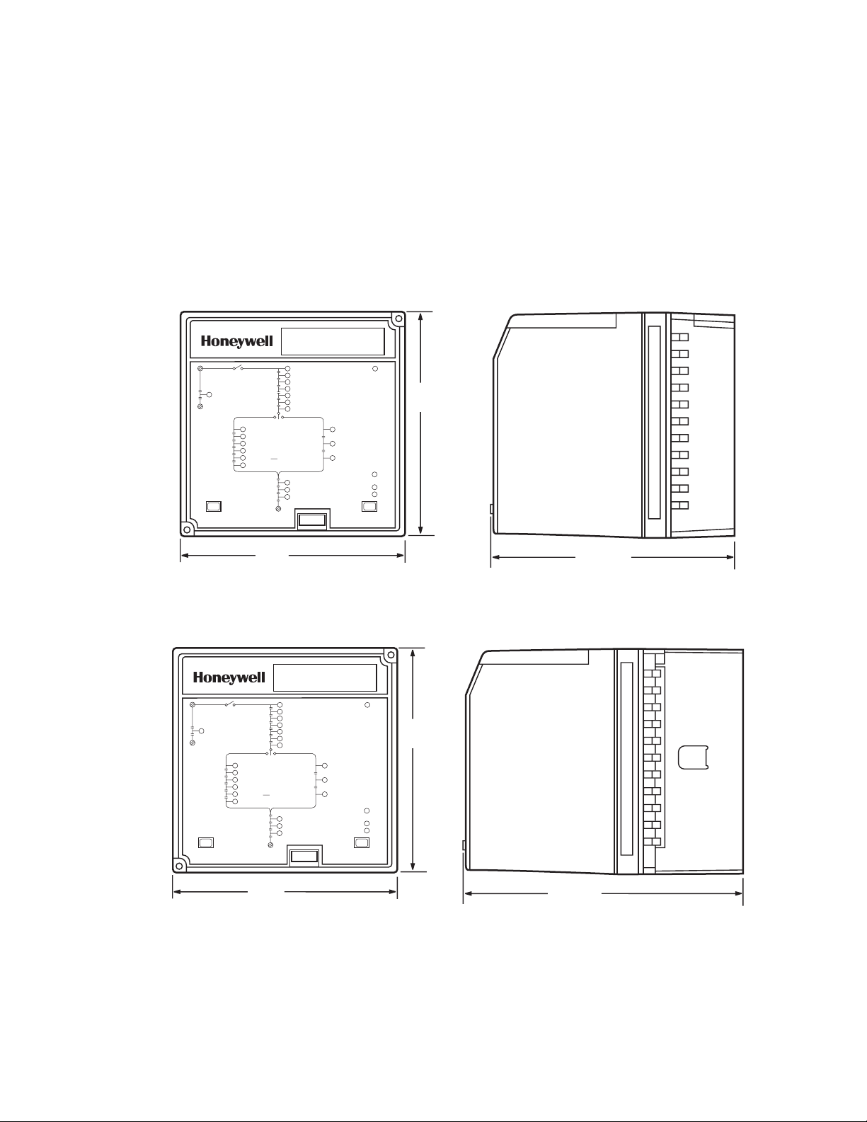
Dimensions: See Fig. 1 and 2.
Weight: 1 lb, 6 oz (0.624 kilogram), unpacked.
Approvals:
Underwriters Laboratories Inc. Listed: File No. MH17367,
Guide No. MJAT.
EXPANDED ANNUNCIATOR
Gas Select
High Gas Pressure
Low Gas Pressure
System Lockout
c
Power
First Out
Current
Select
L1
Proof of Closure
Preignition Interlocks
Reset
Fuel Selection
Oil Select
High Oil Pressure
Low Oil Pressure
High Oil Temperature
Low Oil Temperature
Atomizing Switch
Interlocks
Burner Switch
Operating Control
Auxiliary Limit 1
Auxiliary Limit 2
Low Water Cutoff
High Limit
Atomizing Limit 3
Airflow Switch
Auxiliary Interlock 4
Auxiliary Interlock 5
b
a
5
(127)
Canadian Standards Association certified: LR95329.
Factory Mutual Approved.
IRI Acceptable.
Federal Communications Commission: Part 15, Class B
Emissions.
Required Components;
Q7800A or Q7800B universal Wiring Subbase.
RM7800 SERIES Relay Module.
S7800 Keyboard Display Module or S7810 Data ControlBus™
Module.
Accessories:
S7810M Modbus™ Module.
12
13
14
15
16
17
20 19 18
21
22
5 (127)
5-5/16 (135)
M5182
Fig. 1. Mounting dimensions of S7830 Expanded Annunciator and Q7800A Wiring Subbase in in. (mm).
EXPANDED ANNUNCIATOR
L1
Proof of Closure
Preignition Interlocks
Reset
Fuel Selection
Oil Select
High Oil Pressure
Low Oil Pressure
High Oil Temperature
Low Oil Temperature
Atomizing Switch
Interlocks
5 (127)
Burner Switch
Operating Control
Auxiliary Limit 1
Auxiliary Limit 2
Low Water Cutoff
High Limit
Atomizing imit 3
Airflow Switch
Auxiliary Interlock 4
Auxiliary Interlock 5
a b c
Power
Gas Select
High Gas Pressure
Low Gas Pressure
System Lockout
First Out
Current
Select
5
(127)
22 21 20 19 18 17 16 15 14 13 12
6-9/64 (156)
M5183
Fig. 2. Mounting dimensions of S7830 Expanded Annunciator and Q7800B Wiring Subbase in in. (mm).
3 65-0101—03
Page 4

7800 SERIES S7830 EXPANDED ANNUNCIATOR
PRINCIPAL TECHNICAL FEATURES
The S7830 Expanded Annunciator is an enhancement
module for use with 7800 SERIES Relay Modules. The S7830
is a microprocessor-based device designed to monitor the
status of a series string of limit, control and interlock contacts
for a commercial or industrial burner. The S7830 acts as a
system monitor and enhances fault and status messages for
the 7800 SERIES burner control.
ControlBus Communications
The S7830 provides interfaces with the 7800 SERIES Relay
module through a three-wire RS-485 interface. Using this
communications bus, the S7830 provides additional first-out
annunciation, burner hold, and current status information for
the control, limit and interlock string of the burner equipment.
LED Array
The S7830 provides visual indication of the status of the
burner equipment control, limit and interlock string. The string
of contact and switch points are individually identified with a
colored LED. When power is present at the contact point, the
LED is lighted. When the contact point is de-energized, the
LED is dark. If the contact or switch is identified as the first-out
annunciation point, the LED flashes if the RM78X0L,
RM7838B,C with the Lockout Feature is used or if the feature
is enabled (RM7895, 6, 7, or 8 with JR2 configuration resistor
removed).
Opto-Isolator Coupling
The S7830 uses opto-isolators to monitor the limit string and
couple the line voltage input to the microprocessor. An optoisolator allows a microprocessor to determine the status of
line voltage at control, limit or interlock switch points. Using
this capability, the microprocessor is able to determine the
current as well as first-out status of 23 digital points, each
representing specific burner control, limit or interlock switches.
INSTALLATION
WARNING
Fire or Explosion Hazard.
Can cause severe injury, death or property
damage.
Verification of safety requirements must be performed
each time a control is installed on a burner to prevent
possible hazardous burner operation.
When Installing This Product…
1. Read these instructions carefully. Failure to follow them
could damage the product or cause a hazardous
condition.
2. Check the ratings given in the instructions and on the
product to make sure the product is suitable for your
application.
3. Installer must be a trained, experienced flame
safeguard technician.
4. After installation is complete, check out the product
operation as provided in these instruction.
WARNING
Electrical Shock Hazard.
Can cause severe injury, death or equipment
damage.
1. Disconnect the power supply before beginning
installation to prevent electrical shock and
equipment damage. More than one power supply
disconnect can be involved.
2. Wiring connections for the S7830 are unique;
therefore, refer to Fig. 3, 4, 5 for proper subbase
wiring.
3. Wiring must comply with all applicable codes,
ordinances and regulations.
4. Wiring must comply with NEC Class 1 (Line
Voltage) wiring.
5. The S7830 should not interfere with the proper
safety operation of the controls, limits and interlocks
it is monitoring. After installation, check each
control, limit and interlock to ensure that it is
operating properly. DO NOT PLACE JUMPER
WIRES ACROSS THE INSTALLATION
CONTROLS, LIMITS AND INTERLOCKS.
65-0101—03 4
Page 5

7800 SERIES S7830 EXPANDED ANNUNCIATOR
IMPORTANT
1. This equipment generates, uses and can radiate
radio frequency energy and, if not installed and used
in accordance with these instructions, may cause
interference for radio communications. It has been
tested and found to comply with the limits of a Class
B computing device of part 15 of FCC rules, which
are designed to provide reasonable protection
against such interference when operated in a
commercial environment. Operation of this
equipment in a residential area may cause
interference; in which case, the user, at their own
expense, may be required to take whatever
measures are required to correct this interference.
2. This digital apparatus does not exceed the Class B
limits for radio noise, set out in the Radio Interference Regulations of the Canadian Department of
Communications.
3. If a control, limit or interlock is not used with the
installation, a jumper must be installed in the S7830
wiring subbase. DO NOT PLACE JUMPER WIRES
ACROSS THE INSTALLATION CONTROL, LIMITS
AND INTERLOCKS. For example, if Auxiliary Limit #
1(Aux Limit#1) is not used, place a jumper wire
between terminals 6 and 7 on the S7830 wiring
subbase.
4. For straight gas burner applications, the oil limit and
interlock inputs DO NOT need to be jumpered.
5. For straight oil burner applications, the gas limit and
interlock inputs DO NOT need to be jumpered.
6. For combination gas-oil burner applications, a
double pole, double throw (dpdt) fuel select switch is
required. See Fig. 3.
7. For communications ControlBus connections in
excess of 100 feet (30 meters), a 120 ohm, 1/4 watt
minimum, termination resistor may be required
across terminals 1(a) and 2(b) of the electrical connectors. Cable shield must be terminated to ground
at both ends. If shielded cable is NOT used, use
three-wire twisted cable.
8. The 7800 SERIES Relay Module control point can
be tied into the S7830:
• For dual fuel burners, from terminals 6 to 11,
inclusive.
• For single fuel burners, from terminals 6 to 9,
inclusive.
Humidity
Install the S7830 where the relative humidity never reaches
the saturation point. The S7830 is designed to operate in a
maximum 85% relative humidity, continuous, noncondensing,
moisture environment. Condensing moisture can cause
erratic operation.
Vibration
Do not install the S7830 where it could be subjected to
vibration in excess of 0.5G continuous, maximum.
Weather
The S7830 is not designed to be weather tight. If installed
outdoors, the S7830 must be protected by a weather-tight,
NEMA 4, enclosure.Mounting Wiring Subbase
NOTE: For installation dimensions, see Fig. 1 or 2.
1. Mount the subbase in any position except horizontally
with the bifurcated subbase contacts pointed down (on
the row F). A vertical mounting position is recommended. Any other position decreases the maximum
ambient temperature rating.
2. Select a location on a wall, burner surface, or within an
electrical control panel. Be sure to allow adequate
clearance for electrical voltage probe tests, electrical
field connections, and wiring of the RS-485 ControlBus
to the 7800 SERIES Relay Module. The S7830 must be
within 1000 feet (305 meters) of the 7800 SERIES
Relay Module for proper communication of first-out
annunciation and current burner status information.
3. Use the back of the subbase as a template to mark the
four screw locations and drill pilot holes.
4. Insert four No. 6 screws for mounting, and tighten
securely.
WIRING
WARNING
Electrical Shock Hazard.
Can cause severe injury, death or property
damage.
Disconnect the power supply from the main
disconnect before beginning installation to prevent
electrical shock and equipment damage. More than
one disconnect can be required.
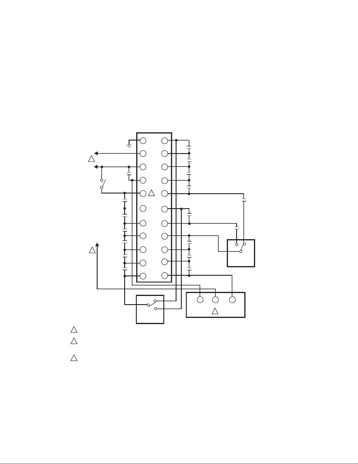
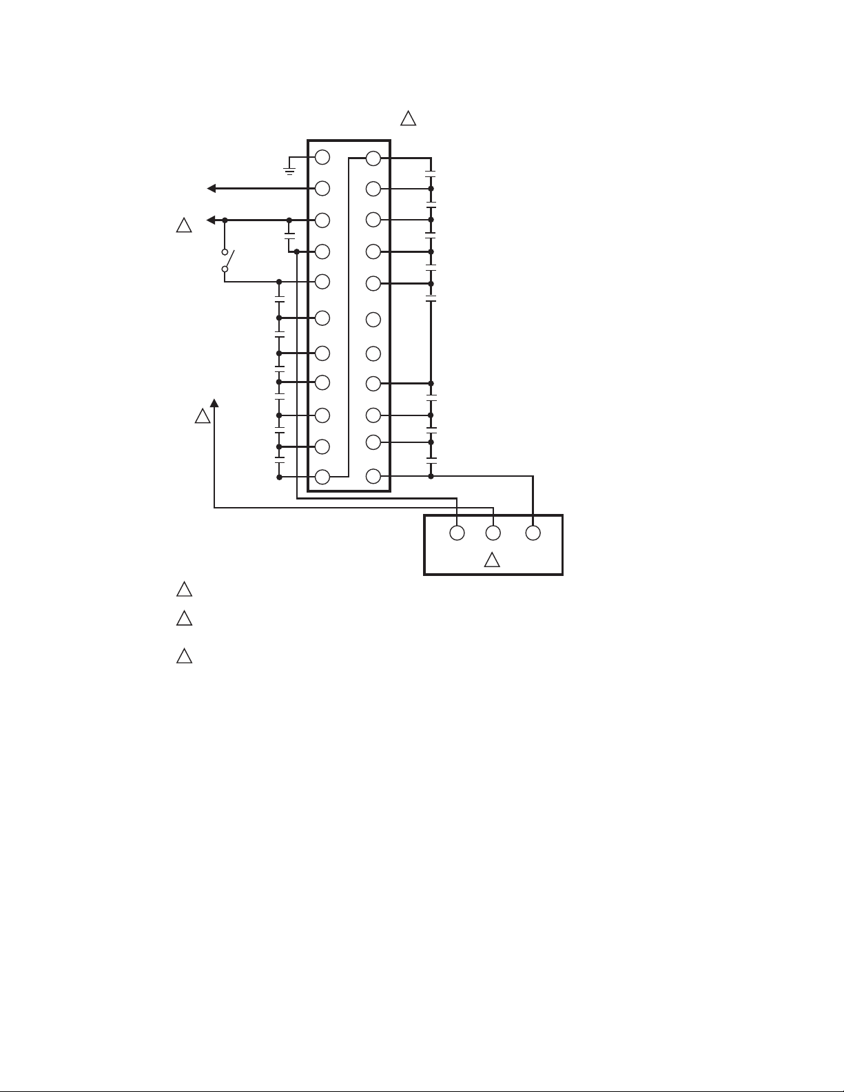
1. Refer to Fig. 3 for proper subbase wiring. The system
wiring must follow the order shown in Fig. 3.
NOTE: With the S7800A1142 Keyboard Display Module, you
can name the limits and interlocks to match your
system.
2. All wiring must comply with all appropriate electrical
codes, ordinances and regulations. Wiring, where
required, must comply with NEC Class 1 (Line Voltage).
3. Recommended wire size and type:
a. Line Voltage:
(1) Use No. 14, 16 or 18 gauge (TTW60C or
THW75C or THHN90C), 600 volt insulation for
all line voltage terminals.
b. RS-485 ControlBus:
(1) Use three-wire twisted cable. Some installations
may require shielded cable; use Belden 8771 or
equivalent. For connections in excess of 100
feet (30 meters), a 120 ohm, 1/4 watt minimum,
termination resistor may be placed across
terminals 1(a) and 2(b) of the electrical
connectors.
4. Recommended grounding practices:
a. The earth ground provides for a connection between
the wiring subbase and the control panel or the
equipment. The earth ground wire must be capable
of conducting the current to blow the 15A type SC
fast blow fuse (or breaker) in the event of an internal
short circuit.
b. The S7830 needs a low impedance ground
connection to the equipment frame which, in turn,
needs a low impedance ground connection to earth
ground. For a ground path to be low impedance at
RF frequencies, the connection must be made with
minimum length conductors that have a maximum
5 65-0101—03
Page 6
7800 SERIES S7830 EXPANDED ANNUNCIATOR
surface area. Wide straps or brackets are preferred
rather than leadwires. Be careful to ensure that
mechanically tightened joints along the ground path,
such as pipe or conduit threads, or surfaces held
together with fasteners, are free of nonconductive
coatings and are protected against corrosion on
mating surfaces.
c. The ControlBus shielded cable, if used, should be
connected to the signal ground terminal 3(c)
provided as a part of the S7830 ControlBus
connector. The shield should be connected at both
ends to earth ground.
5. Recommended Wire Routing:
Q7800 WIRING SUBBASE
FOR S7830 FIELD HOOKUP
L2
1
L1
(HOT)
BURNER
SWITCH
MAIN VALVE
PROOF-OFCLOSURE
OPERATING
CONTROL
AUXILIARY
LIMIT 1
AUXILIARY
LIMIT 2
LOW WATER
CUTOFF
2
HIGH
LIMIT
AUXILIARY
LIMIT 3
a. Do not run high voltage ignition transformer wires in
the same conduit or in close proximity with the ControlBus wiring.
b. Do not route the ControlBus wires in conduit with
line voltage circuits.
6. Maximum wire lengths:
a. The maximum ControlBus cable length depends on
the number of system modules connected, the noise
conditions and the cable used. The maximum length
of all interconnecting wire is 1000 feet (305 meters).
b. S7830 leadwires: the maximum length of the con-
trol, limit and interlock leadwires is 500 feet (152
meters) to the terminal inputs.
1
2
3
4
5
6
7
8
9
10
11
12
13
14
15
16
3
17
18
19
20
21
22
HIGH OIL
PRESSURE
LOW OIL
PRESSURE
HIGH OIL
TEMPERATURE
LOW OIL
TEMPERATURE
HIGH GAS
PRESSURE
AIR FLOW
SWITCH
AUXILIARY
INTERLOCK 4
AUXILIARY
INTERLOCK 5
ATOMIZING
SWITCH
LOW GAS
PRESSURE
GAS
OIL
FUEL SELECT
SWITCH
(1/2 OF DPDT)
FUEL SELECT
SWITCH
(1/2 OF DPDT)
1
120V, 50/60Hz POWER SUPPLY. PROVIDE DISCONNECT MEANS AND OVERLOAD PROTECTION
AS REQUIRED.
2
IN DUAL FUEL SYSTEMS, 7800 SERIES-T6 CAN BE CONNECTED TO ANY POINT FROM 6 TO 11, INCLUSIVE.
(ANYTHING BEFORE THIS POINT IN CONSIDERED A LIMIT AND ANYTHING AFTER IT IS CONSIDERED AN
INTERLOCK DEVICE SPECIFIC.)
PLACE JUMPERS ON S7800 WIRING SUBBASE ONLY FOR UNUSED CONTROL, LIMIT, OR INTERLOCKS.
3
Fig. 3. S7830 wiring hookup—dual fuel.
65-0101—03 6
OIL
GAS
20
PREIGNITION
INTERLOCK
6
CONTROL
2
7
LOCKOUT
INTERLOCK
7800
SERIES
RELAY
WIRING
SUBBASE
TERMINALS
M23113A
Page 7
7800 SERIES S7830 EXPANDED ANNUNCIATOR
L2
L1
1
(HOT)
BURNER
SWITCH
4
2
MAIN VALVE
PROOF-OFCLOSURE
OPERATING
CONTROL
AUXILIARY
LIMIT 1
AUXILIARY
LIMIT 2
LOW WATER
CUTOFF
HIGH
LIMIT
AUXILIARY
LIMIT 3
Q7800 WIRING SUBBASE
FOR S7830 FIELD WIRING
SINGLE FUEL - GAS
G
L2
3
4
5
6
7
8
9
10
11
3
12
13
14
15
16
17
18
19
20
21
22
HIGH GAS
PRESSURE
LOW GAS
PRESSURE
AIR FLOW
SWITCH
AUXILIARY
LIMIT 4
AUXILIARY
LIMIT 5
20
PREIGNITION
INTERLOCK
1
120V, 50/60HZ POWER SUPPLY. PROVIDE DISCONNECT MEANS AND OVERLOAD PROTECTION AS REQUIRED.
2
7800 SERIES TERMINAL 17 CAN BE CONNECTED TO ANY POINT S7830 TERMINAL 17 THROUGH 11 OR 17 THROUGH
19. (ANYTHING BEFORE CONNECTION ARE RUNNING LIMITS AND ANYTHING AFTER IT IS CONSIDERED
LOCKOUT INTERLOCKS DEVICE SPECIFIC.)
PLACE JUMPERS ON S7830 WIRING SUBBASE ONLY FOR UNUSED CONTROL, LIMIT, OR INTERLOCKS.
3
4
IF VPS SPLIT, AFTER OR BOTH IS SELECTED – END THE LIMIT STRING WIRING AT TERMINAL 17 OF THE RELAY
MODULE. – BEGINNING THE REMAINING LIMITS BY CONNECTING TO L1 OR THE RELAY MODULE'S BLOWER
MOTOR TERMINAL. PLEASE NOTE, CONNECTING THE LIMIT STRING TO L1 WILL KEEP THE LIMIT STRING LEDS
OF THE S7830 ILLUMINATED WHEN THE SYSTEM IN STANDBY. USING THE BLOWER MOTOR TERMINAL WILL
SHUT OFF THE LEDS IN STANDBY. MAKE SURE THE LOAD OF THE BLOWER MOTOR AND THE VALVES AND
IGNITION COMBINED DO NOT EXCEED THE RATING OF THE BLOWER MOTOR TERMINAL.
17
CONTROL
2
4
LOCKOUT
INTERLOCK
7800
7
SERIES
WIRING
SUBBASE
TERMINALS
M27949
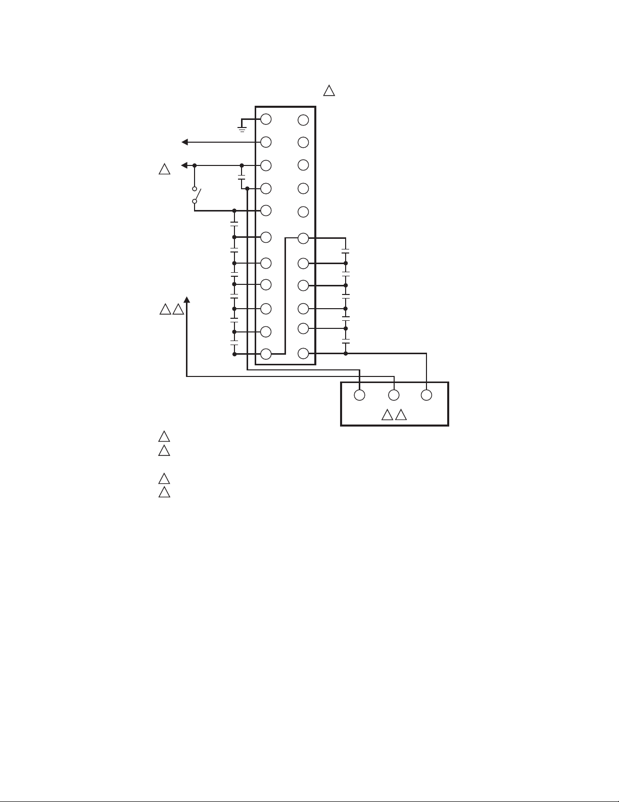
Fig. 4. S7830 wiring hookup—Valve Proving devices with Valve Proving enabled.
7 65-0101—03
Page 8
7800 SERIES S7830 EXPANDED ANNUNCIATOR
L2
L1
1
(HOT)
BURNER
SWITCH
2
MAIN VALVE
PROOF-OFCLOSURE
OPERATING
CONTROL
AUXILIARY
LIMIT 1
AUXILIARY
LIMIT 2
LOW WATER
CUTOFF
HIGH
LIMIT
AUXILIARY
LIMIT 3
Q7800 WIRING SUBBASE
FOR S7830 FIELD WIRING
SINGLE FUEL - OIL
G
L2
3
4
5
6
7
8
9
10
11
3
12
13
14
15
16
17
18
19
20
21
22
HIGH OIL
PRESSURE
LOW OIL
PRESSURE
HIGH OIL
TEMPERATURE
LOW OIL
TEMPERATURE
ATOMIZING
SWITCH
AIR FLOW
SWITCH
AUXILIARY
LIMIT 4
AUXILIARY
LIMIT 5
1
120V, 50/60Hz POWER SUPPLY. PROVIDE DISCONNECT MEANS AND OVERLOAD PROTECTION
AS REQUIRED.
7800 SERIES TERMINAL 6 CAN BE CONNECTED TO ANY POINT S7830 TERMINAL 6 THROUGH 19.
2
(ANYTHING BEFORE CONNECTION ARE RUNNING LIMITS AND ANYTHING AFTER IT IS CONSIDERED
LOCKOUT INTERLOCKS DEVICE SPECIFIC.)
PLACE JUMPERS ON S7830 WIRING SUBBASE ONLY FOR UNUSED CONTROL, LIMIT, OR INTERLOCKS.
3
Fig. 5. S7830 wiring hookup—single fuel: oil.
7. Check the power supply circuit. The voltage and
frequency tolerance must match those of the S7830. Do
not connect the S7830 to a power supply circuit that can
have wide line voltage variations. A separate power
supply circuit may be required for the S7830. Add the
required disconnect means and overload protection.
8. Check all wiring circuits (see Fig. 3) before installing the
S7830 on the wiring subbase.
9. Install all electrical connectors.
10. Restore power to the panel.
Mounting the S7830
NOTE: For installation dimensions, see Fig. 1 or 2.
20
PREIGNITION
INTERLOCK
6
CONTROL
2
LOCKOUT
INTERLOCK
7800
7
SERIES
WIRING
SUBBASE
TERMINALS
M23115A
1. Mount the S7830 vertically (see Fig. 3, 4 and 5) or
horizontally with the knifeblade terminals pointing
downward. When mounted on the Q7800A Wiring
Subbase, the S7830 must be in an electrical enclosure.
2. Select the location in the electrical enclosure. Be sure to
allow clearances for servicing, electrical signal voltage
probes and electrical connections. Allow an optional
three inches (8 cm) minimum on both sides of the
S7830 for electrical signal voltage probes.
3. Make sure no subbase wiring is projecting beyond the
terminal blocks. Tuck in wiring against the back of the
subbase so that it does not interfere with the knifeblade
terminals or bifurcated contacts.
4. Mount the S7830 by aligning the four L-shaped corner
guides and knifeblade terminals with the bifurcated contacts on the wiring subbase and securely tightening the
two mounting screws.
65-0101—03 8
Page 9
S7830 RS485 CONTROLBUS CONNECTOR
A
2
a
120 OHM
RESISTOR
7800 SERIES
RELAY MODULE
S7800 CONNECTION
1
3
2
3
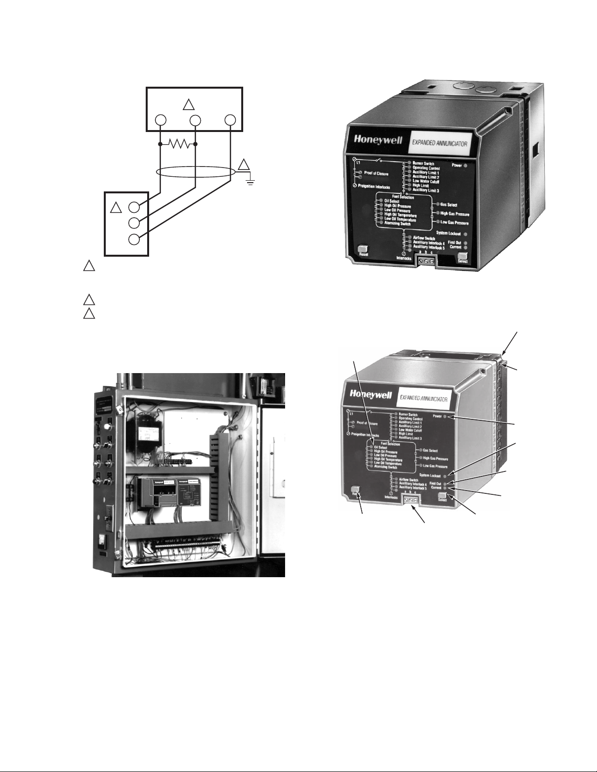
THREE WIRE SHIELDED CABLE AND 120 OHM (1/4 WATT)
1
TERMINATING RESISTOR MAY BE REQUIRED. CABLE SHIELD
MUST BE TERMINATED TO GROUND AT BOTH ENDS. IF
SHIELDED CABLE IS NOT USED, TWISTED PAIR MUST BE USED.
MAXIMUM RS485 LENGTH: 1000 FEET (305 METERS).
2
5 WIRE CONNECTOR (203541) LOCATED ON THE S7800 DISPLAY.
3
b
c
1
Fig. 6. Wiring the RS-485 ControlBus.
M27947
7800 SERIES S7830 EXPANDED ANNUNCIATOR
Fig. 8. Wall or burner installation using Q7800B wiring
subbase.
L SHAPE
CONTROL LIMIT
ND INTERLOCK
DIGITAL POINT
LEDs
CORNER
GUIDES
MOUNTING
SCREW
POWER
LED
SYSTEM
LOCKOUT
LED
FIRST OUT
LED
CURRENT LED
RESET
KEY
RS485
CONTROLBUS
CONNECTOR
SELECT
KEY
M20410
Fig. 9. S7830 Expanded Annunciator for cabinet
Fig. 7. Electrical panel installation.
OPERATION
installation using Q7800A wiring subbase.
The S7830 is designed to operate in conjunction with 7800
SERIES Relay Modules to enhance information for causes of
burner lockouts and sequence status by monitoring up to 21
digital contact points. Current burner status and lockout
information is displayed at the S7830 through an array of 26
LED and also on the face of the S7800 Keyboard Display
Module. The information from the S7830 is communicated
through a three-wire twisted ControlBus communications link
to the S7800.
9 65-0101—03
Page 10

7800 SERIES S7830 EXPANDED ANNUNCIATOR
NOTE: Not all 7800 SERIES devices lock out for an open
interlock. Annunciation is available as hold
messages but an alarm will not be generated.
First-Out Annunciation
The S7830 does not cause burner lockouts. Only the 7800
SERIES Relay Modules with the lockout feature (RM78X0L,
RM7838B, C or RM7895, 6, 7, 8 with configuration resistor
feature, JR2 clipped) can cause a burner lockout (safety
shutdown) for abnormal interlock conditions. From the time a
lockout occurs, the expanded first-out annunciation is
communicated as follows:
1. The 7800 SERIES Relay Module causes a lockout due
to, for example, the opening of the Lockout Interlock
circuit.
2. The 7800 SERIES Relay Module communicates the
lockout status, including the time when the fault
occurred, to any modules connected to the RS-485
ControlBus communication network.
3. The S7830 recognizes the lockout status of the 7800
SERIES Relay Module and the time when the fault
occurred.
4. The S7830 begins to review the status of all switched
inputs on a grouping of several line cycles time duration.
When identifying a normal status of all switched inputs,
the S7830 will advance one line cycle grouping to
identify the first switched input that opened after the
normal status. This switch point, for example, air flow
switch, is identified as the first-out annunciation point.
5. This first-out information is communicated by the S7830
to:
a. The 7800 SERIES Relay Module to enhance the
lockout display message, for example from Lockout
Interlock fault to Airflow Switch fault.
b. The array of 26 status LED on the face of the S7830
that are latched to the lockout mode to visually
indicate which switch is the first-out point. For the
example being used:
(1) All LED electrically upstream from the airflow
switch will be illuminated constantly.
(2) The airflow switch LED will flash on and off to
indicate that this switch was the first-out cause of
the lockout condition.
(3) Any LED electrically downstream from the
first-out point will remain dark because the circuit
upstream of that point has been broken.
(4) The first-out LED will be latched to indicate the
mode of the 26-led array.
6. When the lockout is cleared by resetting the 7800
SERIES Relay Module, the S7830 is automatically
changed from first-out to current.
Current Status
The S7830 provides current status information, through the
RS-485 ControlBus, defining which switch point is causing a
hold condition. The 7800 SERIES Relay Module places the
burner in Standby when the control input, terminal 6, opens
(terminal 17 on VP devices: RM7898, RM7840G/L and
RM7800L). The exact switch causing the burner to enter
Standby may be one of several controls, limits or interlocks.
The S7830, through the RS-485 ControlBus, communicates
the current status of the 21 monitored digital contacts points
twice each second. For example, if the Standby hold is being
caused by the Burner Switch being open, the Standby hold
message will be enhanced to identify the Burner Switch,
providing information that identifies the reason for the hold.
S7830 User Interface
LED States
The array of 26 LED can have the following states:
1. Digital Points:
a. The digital contact switch points can have one of
three states:
(1) LED ON indicates power is present at the S7830
terminal monitoring that switch.
(2) LED OFF indicates power is absent at the S7830
terminal monitoring that switch.
(3) LED FLASHING indicates the switch that is the
cause of the lockout, first-out point.
b. Digital Points LED:
(1) Main Valve Proof of Closure
(2) Burner Switch
(3) Operating Control
(4) Auxiliary Limit # 1
(5) Auxiliary Limit # 2
(6) Low Water Cutoff
(7) High Limit
(8) Auxiliary Limit # 3
(9) Oil Select Switch
(10)High Oil Pressure
(11)Low Oil Pressure
(12)High Oil Temperature
(13)Low Oil Temperature
(14)Gas Select Switch
(15)High Gas Pressure
(16)Low Gas Pressure or Atomizing Switch
(17)Air Flow Switch
(18)Auxiliary Interlock # 4
(19)Auxiliary Interlock # 5
(20)Other Preignition Interlock
(21)Other Lockout Interlock
2. Power LED
a. The Power LED can have one of three states:
(1) LED ON indicates an abnormal condition that
shows power is present at the S7830, but the
device is inoperative (reset the S7830).
(2) LED OFF indicates:
(a)Power is absent at the S7830.
(b)Power is present at the S7830, but the Power
LED is defective.
(c)Power is present at the S7830, the Power
LED is not burned out, but the device is
inoperative. (Reset the S7830.)
(3) LED FLASHING (OFF briefly every four
seconds) indicates power is present at the
S7830 and the device is operating properly.
3. System Lockout LED
a. The System Lockout LED can have one of two
states:
(1) LED ON indicates the 7800 SERIES Relay Mod-
ule is in a lockout state.
(2) LED OFF indicates the 7800 SERIES Relay
Module is in a normal operating status, power is
off, or the LED is defective.
65-0101—03 10
Page 11

7800 SERIES S7830 EXPANDED ANNUNCIATOR
4. First-out LED
a. The First-out LED can have one of three states:
(1) LED ON indicates the LED array is latched in a
mode showing the status at the time of the
lockout.
(2) LED OFF indicates the LED array is in a Current
Status mode, power is off, or the LED is
defective.
(3) LED FLASHING indicates the Select keypad is
being depressed constantly (four seconds or
longer) and a lockout is not present.
5. Current LED
a. The Current LED can have one of two states:
(1) LED ON indicates the LED array is in a Current
status.
(2) LED OFF indicates the LED array is latched in a
first-out mode, power is off or the LED is
defective.
Select Keypad Functions
The Select Keypad provides two functions:
1. When depressed momentarily, the S7830 mode will
toggle between lockout (first-out) and Current status.
Therefore, the operator can actively switch back and
forth between these two modes to define the status of
the 21 digital switched inputs.
2. When depressed constantly (four seconds), all 25 LED
(exclusive of the POWER LED) in the array will be
forced on. This is a means to check to make certain that
an LED can illuminate or is operating properly.
Reset Keypad Function
The Reset Keypad is used to cause an electrical reset of the
S7830. If the operation of the S7830 is in question, an attempt
can be made to reset the internal microprocessor. It is not
necessary to depress the Reset Keypad after a system
lockout. Once the 7800 SERIES Relay Module is reset, the
S7830 LED array automatically will be reset to the Current
status mode.
Display Messages
The S7830 is used to enhance the lockout and hold
information generated by the 7800 SERIES Relay Module,
and allows point-by-point interrogation of the digital switch
points by using the S7800 Keyboard Display Module. This
information is contained within an Expanded Annunciator
informational index (see Table 2).
S7800 Expanded Annunciator Informational Index
Using the S7800 Keyboard Display Module, referring to
Table 2, the individual ON/OFF status of 22 digital points can
be monitored. The display message values for the Expanded
Annunciator Informational Index are also explained in Table 2.
Hold Messages
Using the S7800 Keyboard Display Module, the S7830
provides 16 HOLD messages. The HOLD messages are
summarized in Table 3.
Lockout Messages
Using the S7800 Keyboard Display Module, the S7830
provides 20 enhanced LOCKOUT messages. The LOCKOUT
messages are summarized in Table 4.
Table 2. Expanded Annunciator Informational Index.
Selectable Message Display Value Description
EA not connected — The Expanded Annunciator is not connected.
CS: Reference Table 5 Current status of Expanded Annunciator (EA) digital switch points.
Valve Close 1 or 0 The main valve proof of closure switch is open (0) or closed (1).
Burner Switch The burner switch is open (0) or closed (1).
OperControl The operating control (pressure or temperature) switch is open (0) or closed (1).
Aux Limit 1 An auxiliary limit switch is open (0) or closed (1).
Aux Limit 2 An auxiliary limit switch is open (0) or closed (1).
LWCO The low water cutoff switch is open (0) or closed (1).
High Limit The appliance high limit (pressure or temperature) switch is open (0) or closed (1).
Aux Limit 3 An auxiliary limit switch is open (0) or closed (1).
Oil Select The fuel oil select switch is open (0) or closed (1).
HiOilPres The high oil pressure limit switch is open (0) or closed (1).
LowOilPres The low oil pressure limit switch is open (0) or closed (1).
HiOilTemp The high oil temperature limit switch is open (0) or closed (1).
LowOilTemp The low oil temperature limit switch is open (0) or closed (1).
Atomize Sw The oil atomizing proving switch is open (0) or closed (1).
Gas Select The gas select switch is open (0) or closed (1).
HiGasPres The high gas pressure limit switch is open (0) or closed (1).
a
11 65-0101—03
Page 12

7800 SERIES S7830 EXPANDED ANNUNCIATOR
Table 2. Expanded Annunciator Informational Index.
a
Selectable Message Display Value Description
LowGasPres 1 or 0 The low gas pressure limit switch is open (0) or closed (1).
Airflow Sw The airflow interlock switch is open (0) or closed (1).
Aux ILK 4 An auxiliary interlock switch is open (0) or closed (1).
Aux ILK 5 An auxiliary interlock switch is open (0) or closed (1).
EA Fault Code nnn The fault code number, identifying the specific Expanded Annunciator fault.
SW Rev. nnnn Identifies the software revision of the S7830.
a
Displayed message can be changed using the S7800A1142 Keyboard Display Module.
Table 3. Expanded Annunciator Hold Codes.
a
Message Description
BURNER OFF (Burner Switch) Burner switch is open (0) and keeping the burner in an Off condition.
STANDBY HOLD: (Aux. Limit # 1) Auxiliary Limit # 1 is open (0) and keeping the burner in Standby.
STANDBY HOLD: (Aux. Limit # 2) Auxiliary Limit # 2 is open (0) and keeping the burner in Standby.
STANDBY HOLD: (LWCO) Low water cutoff is open (0) and keeping the burner in Standby.
STANDBY HOLD: (High LImit) The appliance high limit is open (0) and keeping the burner in Standby.
STANDBY HOLD: (Aux. Limit # 3) Auxiliary Limit # 3 is open (0) and keeping the burner in Standby.
STANDBY HOLD: (FuelSelectOff) Both fuel select inputs are open (0) and keeping the burner in Standby.
STANDBY HOLD: (BothFuelSelect) Both fuel select inputs are closed (1) and keeping the burner in Standby.
STANDBY HOLD: (High Oil Press) High oil pressure limit is open (0) and keeping the burner in Standby.
STANDBY HOLD: (Low Oil Press) Low oil pressure limit is open (0) and keeping the burner in Standby.
STANDBY HOLD: (High Oil Temp) High oil temperature limit is open (0) and keeping the burner in Standby.
STANDBY HOLD: (Low Oil Temp) Low oil temperature limit is open (0) and keeping the burner in Standby.
STANDBY HOLD: (Atomizing Sw.) Oil atomizing switch is open (0) and keeping the burner in Standby.
STANDBY HOLD: (High Gas Press) High gas pressure limit is open (0) and keeping the burner in Standby.
STANDBY HOLD: (Low Gas Press) Low gas pressure limit is open (0) and keeping the burner in Standby.
STANDBY HOLD: (Circuit Fault) Control input is not energized.
a
Displayed message can be changed using the S7800A1142 Keyboard Display Module.
65-0101—03 12
Page 13

7800 SERIES S7830 EXPANDED ANNUNCIATOR
Table 4. Expanded Annunciator Lockout Codes.
Message Description
LOCKOUT nna
Auxiliary Limit # 1 was open.
*Aux.Limit#1*
LOCKOUT nnb
Auxiliary Limit # 2 was open.
*Aux.Limit#2*
LOCKOUT nnc
Low water cutoff was open.
*LWCO*
LOCKOUT nnd
Appliance high limit was exceeded.
*High Limit*
LOCKOUT nne
Auxiliary Limit # 3 was open.
*Aux.Limit#3*
LOCKOUT nnf
No fuel was selected.
*FuelSelectOff*
LOCKOUT nng
Both fuels were selected.
*BothFuelSelect*
LOCKOUT nnh
Oil pressure was above the high limit setting.
*High Oil Press*
LOCKOUT nni
Oil pressure was below the low limit setting.
*Low Oil Press*
LOCKOUT nnj
Oil temperature was above the high limit setting.
*High Oil Temp*
LOCKOUT nnk
Oil temperature was below the low limit setting.
*Low Oil Temp*
LOCKOUT nnm
Atomizing switch failed to close.
*Atomizing Switch*
LOCKOUT nnn
Gas pressure was above the high limit setting.
*High Gas Press*
LOCKOUT nno
Gas pressure was below the low limit setting.
*Low Gas Press*
LOCKOUT nnp
*Airflow Switch*
LOCKOUT nnq
The airflow switch was open (0) when it should have been closed (1). Or, the airflow switch was
closed (1) when it should have been open (0).
Auxiliary Interlock # 4 was open.
*Aux.ILK#4*
LOCKOUT nnr
Auxiliary Interlock # 5 was open.
*Aux.ILK#5*
LOCKOUT nns
An interlock, electrically downstream of Auxiliary Interlock # 5, was open.
*Other ILKs*
LOCKOUT nny
Main valve proof of closure switch was open.
*Valve Closure*
LOCKOUT nnz
An interlock, electrically downstream of the main valve proof of closure (Valve Closure) was open.
*Other PII*
a
Displayed message can be changed using the S7800A1142 Keyboard Display Module.
a
Table 5. Expanded Annunciator Current Status Messages
Message Description
Burner Sw. Burner Switch
Oper. Control Operating Control
Aux. Limit # 1 Auxiliary Limit # 1
Aux. Limit # 2 Auxiliary Limit # 2
LWCO Low Water Cutoff
High Limit High temperature or pressure limit
Aux. Limit # 3 Auxiliary Limit # 3
a
.
13 65-0101—03
Page 14

7800 SERIES S7830 EXPANDED ANNUNCIATOR
Table 5. Expanded Annunciator Current Status Messages (Continued)
Message Description
FuelSelectOff Fuel Select switch is off.
BothFuelSelect Both fuel select inputs are on.
High Oil Pres. High Oil Pressure
Low Oil Pres. Low Oil Pressure
Low Oil Temp. Low Oil Temperature
Atomizing Sw. Atomizing Switch
High Gas Pres. High Gas Pressure
Low Gas Pres. Low Gas Pressure
Airflow Sw. Airflow Switch
Aux. ILK # 4 Auxiliary Interlock # 4
Aux. ILK # 5 Auxiliary Interlock # 5
a
Displayed message can be changed using the S7800A1142 Keyboard Display Module.
CHECKOUT
Several basic steps can be take to check proper operation of
the S7830.
1. Depress and hold the Select keypad for five seconds.
All 25 LED (Exclusive of the Power LED) should light.
2. Through the S7800 Keyboard Display Module, access
the S7830 Expanded Annunciator Informational Index. If
the S7830 is operating properly, it should be possible to
access the status of all switched points.
3. Open equipment control, limits, and interlock inputs.
The S7830 LED array and S7800 Keyboard Display
Module should indicate the cause of the burner lockout
and switch point status.
IMPORTANT
Restore ALL controls, limits and interlock inputs,
altered in step 3, to proper operation. DO NOT
PLACE JUMPER WIRES ACROSS THE
INSTALLATION CONTROLS, LIMITS AND
INTERLOCKS.
4. If improper operation is identified, check all S7830
wiring against Fig. 3 and correct any errors. If problems
persist, reset the S7830. If problems continue to persist,
replace the S7830 Expanded Annunciator.
NOTE: The S7830 is a monitoring device. If wired correctly,
the S7830 will not shut the system down.
The S7830 can be removed from the wiring subbase
and the equipment should operate in a normal manner and shutdown if limit or interlock were to open.
a
.
65-0101—03 14
Page 15

7800 SERIES S7830 EXPANDED ANNUNCIATOR
15 65-0101—03
Page 16

7800 SERIES S7830 EXPANDED ANNUNCIATOR
Automation and Control Solutions
Honeywell International Inc. Honeywell Limited-Honeywell Limitée
1985 Douglas Drive North 35 Dynamic Drive
Golden Valley, MN 55422 Toronto, Ontario M1V 4Z9
customer.honeywell.com
® U.S. Registered Trademark
© 2008 Honeywell International Inc.
65-0101—03 M.S. Rev. 11-08
 Loading...