

Page 1
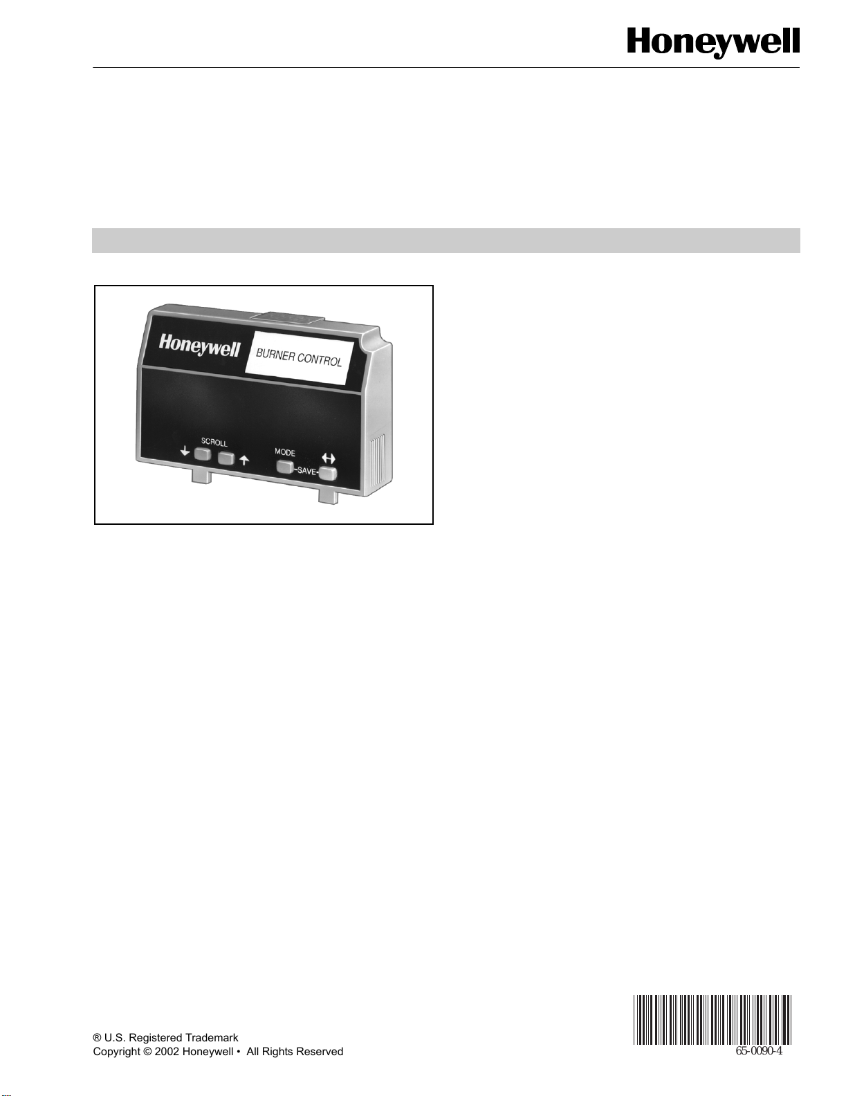
S7800A Keyboard Display Module
APPLICATION
The S7800A Keyboard Display Module (KDM) provides
first-out annunciation and system diagnosis using a two-row
by twenty-column readout. The KDM provides local or remote
annunciation of operation and fault information, remote reset,
report generation, burner control data and diagnostic
information. The KDM is part of the 7800 SERIES of
microprocessor-based burner controls for gas, oil, coal or
combination fuel single burner applications.
The 7800 SERIES is programmed to provide a level of safety,
functional capabilities and features beyond the capacity of
conventional controls.
7800 SERIES
PRODUCT DATA
FEATURES
• Application flexibility.
• Communication interface capability.
• Dependable, long-term operation provided by
microcomputer technology.
• First-out annunciation and system diagnostics
provided by a 2-row by 20-column display.
• First-out expanded annunciation with 24 limit and
interlock Light Emitting Diodes (LED).
• Local or remote annunciation of operation and
fault information.
• UL Class 4 rating when P/N 204718A,C NEMA 4 cover
is used.
Remote reset.
•
• Report generation.
• Burner controller data:
— Sequence status.
— Sequence time.
— Hold status.
— Lockout/alarm status.
— Flame signal strength.
— Expanded annunciator status.
— Total cycles of operation.
— Total hours of operation.
— Fault history of six most recent faults:
• Cycles of operation at time of fault.
• Expanded annunciator data at time of fault.
• Fault message and code.
• Hours of operation at time of fault.
• Sequence status at time of fault.
• Sequence time at time of fault.
® U.S. Registered Trademark
Copyright © 2002 Honeywell • All Rights Reserved
Contents
Application ........................................................................ 1
Features ........................................................................... 1
Specifications ................................................................... 2
Ordering Information ........................................................ 2
Installation ........................................................................ 3
Wiring ............................................................................... 4
Troubleshooting ................................................................ 11
65-0090-4
Page 2
7800 SERIES S7800A KEYBOARD DISPLAY MODULE
— Diagnostic information:
• Device type.
•Flame amplifier type.
• Flame failure response time (FFRT).
•Manufacturing code.
•On-Off status of all digital inputs and
outputs.
•PREPURGE time selected.
•Software revision and version of 7800
SE RI ES
Relay Module and KDM.
•Status of configuration jumpers.
•Status of Run/Test Switch.
SPECIFICATIONS
Electrical Ratings:
Voltage and Frequency: 13 Vdc peak full wave rectified
(+20/-15%).
Power Dissipation: 7W maximum.
VA Consumption: 2 VA maximum.
Terminal Ratings:
Power: 13 Vdc peak full wave rectified.
Earth Ground.
Environmental Ratings:
Ambient Temperature Ranges:
Operating: -40°F (-40°C) to +140°F (+60°C).
Storage: -60°F (-51°C) to +150°F (+66°C).
Humidity: 85 percent relative humidity continuous,
noncondensing.
S7800A1050 Italian language display.
S7800A1068 Spanish language display.
S7800A1118 Japanese (Katakana) language display.
S7800A1126 Portuguese language display.
BURNER CONTROL
2-3/4
(69)
15/
32
(12)
1-15/16
(49)
29/32
(23)
SCROLL MODE
19/32
(15)
5/32 (4)
4-27/32 (123)
1-1/4
(32)
7/16 (11)
2-7/16 (62)
3-7/8 (99)
SAVE
4-3/32 (104)
1-1/32
(26)
13/
32
(11)
5/32
(4)
1/2
(13)
5/16
(8)
2-1/32
(52)
5/15
(8)
M5002B
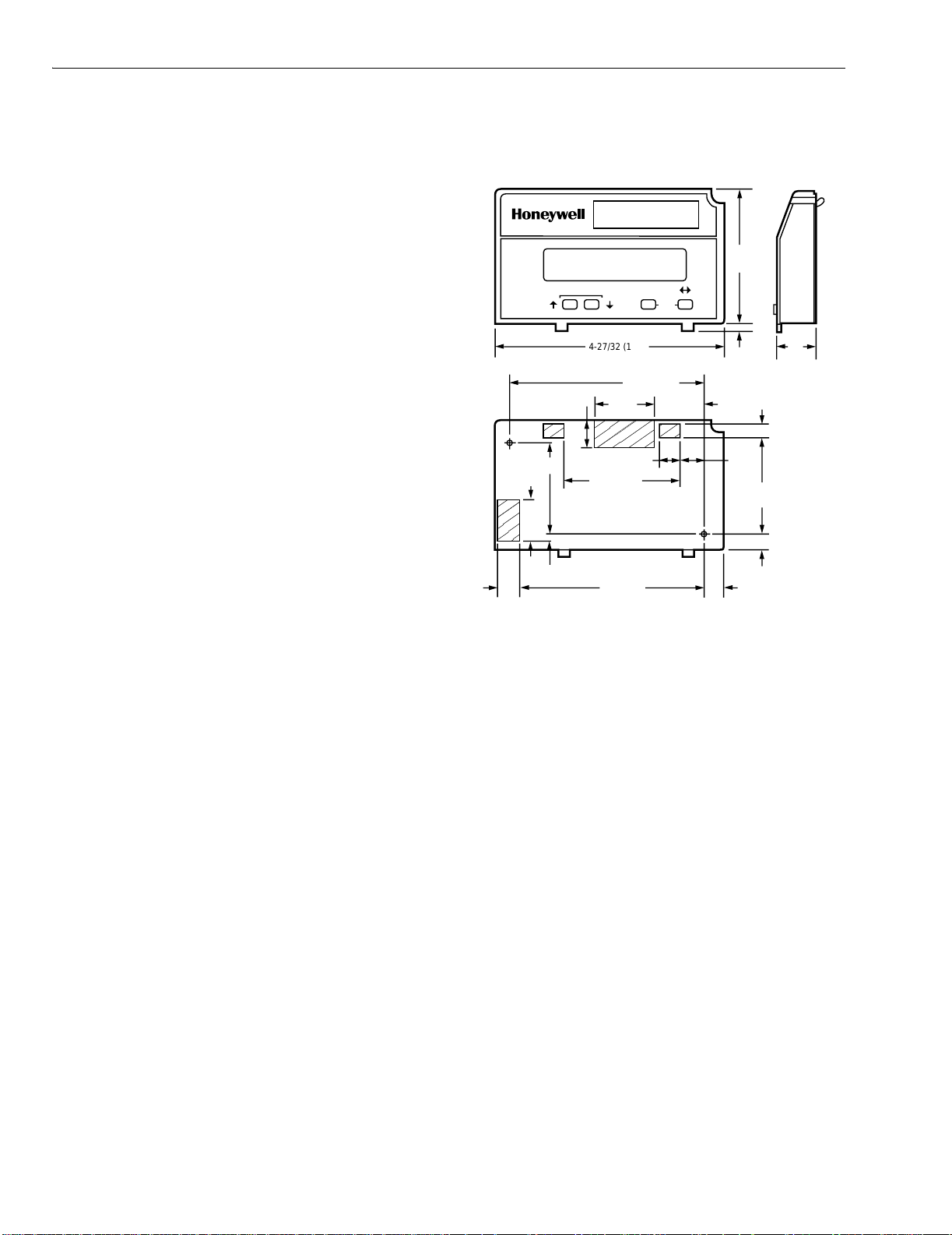
Fig. 1. Approximate dimensions of S7800 in in. (mm).
29/32
(23)
NOTE: UL Class 4 rating when P/N 204718A,C NEMA 4
Cover is used.
Approvals:
Underwriters Laboratories Inc. Listed:
File No. MP268, Guide No. MCCZ.
Vibration: 0.5G environment.
Canadian Standards Association Certified:
No. LR9S329-3.
Mechanical:
Dimensions: See Fig. 1.
Weight: 4 ounces (124 grams), unpacked.
Factory Mutual Approved: Report No. J.I.1V9A0.AF.
IRI: Acceptable.
Federal Communications Commission: Part 15,
Class B emissions.
Display: 40 character (2 rows by 20 columns).
EN60730: For compliance with remote KDM mounting
requirements, provide electrical insulation separation by
Languages:
S7800A1001 English language display.
S7800A1035 French language display.
insulation using double or reinforced insulation. Do this by:
Optically isolating the communication or remote reset lines
from the control cabinet, or provide physical separation
S7800A1043 German language display.
ORDERING INFORMATION
When purchasing replacement and modernization products from your TRADELINE® wholesaler or distributor, refer to the
TRADELINE® Catalog or price sheets for complete ordering number.
If you have additional questions, need further information, or would like to comment on our products or services, please write or
phone:
1. Your local Home and Building Control Sales Office (check white pages of your phone directory).
2. Home and Building Control Customer Relations
Honeywell, 1885 Douglas Drive North
Minneapolis, Minnesota 55422-4386
In Canada—Honeywell Limited/Honeywell Limitée, 35 Dynamic Drive, Scarborough, Ontario M1V 4Z9.
International Sales and Service Offices in all principal cities of the world. Manufacturing in Australia, Canada, Finland, France,
Germany, Japan, Mexico, Netherlands, Spain, Taiwan, United Kingdom, U.S.A.
65-0090—4 2
Page 3
7800 SERIES S7800A KEYBOARD DISPLAY MODULE
from the communication or remote display cover assembly
(part number 204718A) or other suitable enclosure that
meets the IP40 class of protection.
Accessories:
203541 ControlBus 5-wire Electrical Connector.
S7810A1009 Data ControlBus Module™.
203765 Remote Display Mounting Bracket.
221818A 60 in. (1.5m) Extension Cable Assembly.
221818C 120 in. (3m) Extension Cable Assembly.
204718A NEMA 4 Cover Assembly for S7800A KDM.
204718B NEMA 1 Cover Assembly for S7800A KDM.
204718C NEMA 4 Cover Assembly for S7800A KDM with
reset button.
205321B Remote Display Flush Mount Kit.
INSTALLATION
WARNING
Electrical Shock Hazard.
Can cause severe injury or death.
Disconnect the power supply before beginning
installation to prevent electrical shock and equipment
damage. More than one power supply disconnect can
be involved.
Humidity
Install the S7800A where the relative humidity never reaches
the saturation point. The S7800 is designed to operate in a
maximum 85% RH continuous, noncondensing, moisture
environment.
Vibration
Do not install the S7800A where it can be subjected to
vibration in excess of 0.5G continuous maximum vibration.
Weather
The S7800A is not designed to be weather tight. If installed
outdoors, the S7800A must be protected by an approved
weather-tight enclosure such as the 204718A or 204718C
NEMA 4 Enclosure listed in Accessories.
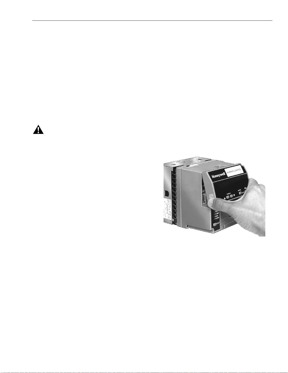
Mounting KDM on 7800 SERIES Relay Module.
1. Align the two interlocking ears of the KDM with the two
mating slots on the 7800 SERIES Relay Module. See
Fig. 2.
When Installing This Product…
1. Read these instructions carefully. Failure to follow them
could damage the product or cause a hazardous
condition.
2. Check the ratings given in the instructions and marked
on the product to make sure the product is suitable for
your application.
3. Installer must be a trained, experienced, flame
safeguard service technician.
4. After installation is complete, check out the product
operation as provided in these instructions.
5. Be sure wiring complies with all applicable codes,
ordinances and regulations.
6. See Fig. 5, 6 and 7 for S7800A unique wiring
connections.
IMPORTANT
1.This equipment generates, uses and can radiate
radio frequency energy and, if not installed and used
in accordance with the instructions, can cause
interference to radio communications. It has been
tested and found to comply with the limits for a Class
B computing device of Part 15 of FCC rules which
are designed to provided reasonable protection
against such interference when operated in a
commercial environment. Operation of this
equipment in a residential area can cause
interference, in which case, users, at their own
expense, can be required to take whatever
measures are required to correct this interference.
2.This digital apparatus does not exceed the Class B
limits for radio noise for digital apparatus set out in
the Radio Interference Regulations of the Canadian
Department of Communications.
Fig. 2. Keyboard display module mounting.
2. Insert the two interlocking ears into the two mating slots
and, with a hinge action, push on the lower corners of
the KDM to secure it to the 7800 SERIES Relay
Module.
3. Make sure the KDM is firmly in place.
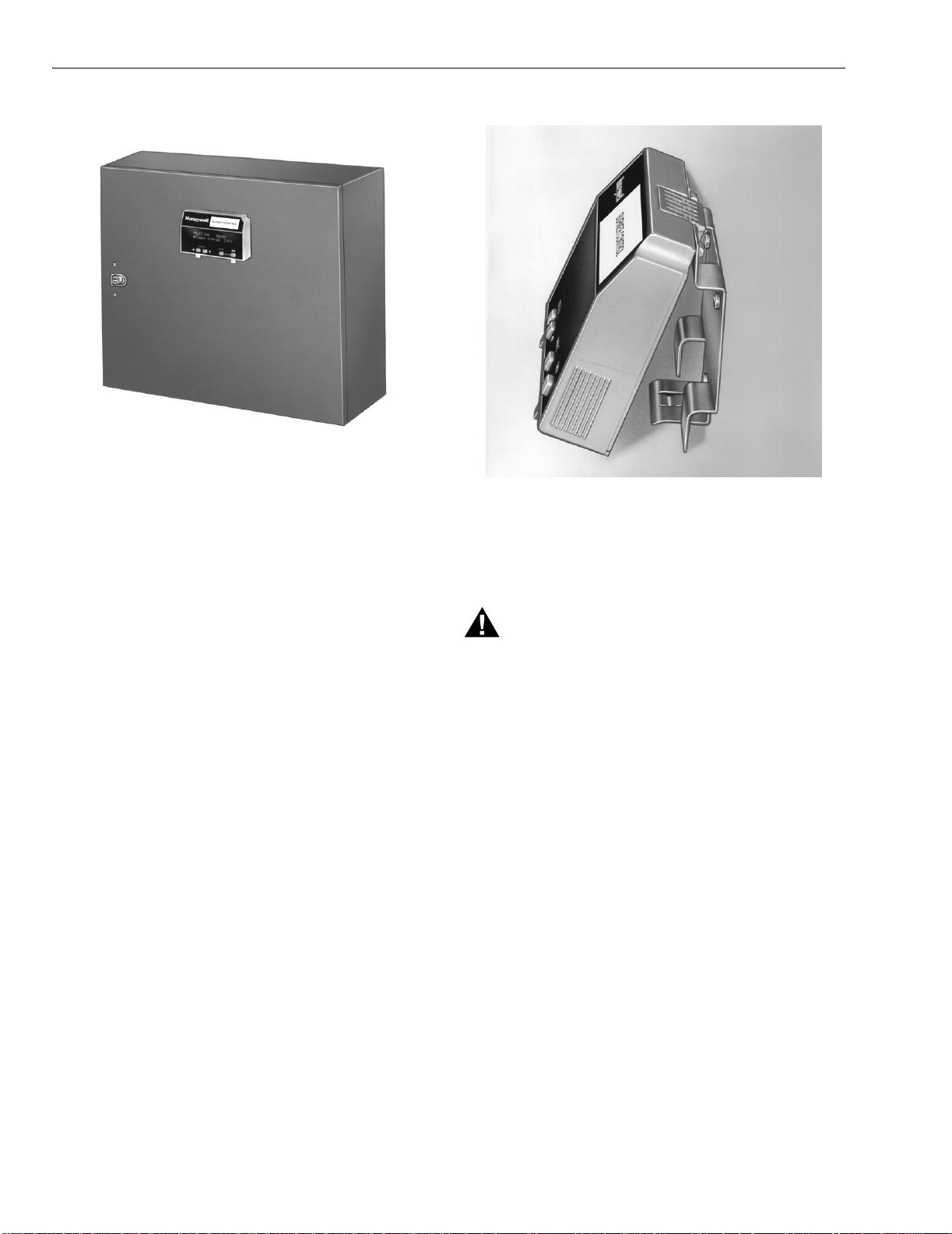
Remote Mounting KDM
The KDM can be mounted either on the face of a panel door
or on other remote locations. See Fig. 3. When mounting the
KDM on the face of a door panel, closely follow these
instructions:
3 65-0090—4
Page 4
7800 SERIES S7800A KEYBOARD DISPLAY MODULE
Door Panel Mounting
Fig. 3. Panel mounting of a keyboard display module.
1. Select the location on the door panel for flush mounting.
2. Pay attention to the insertion dimensions of the two
KDM screws, two interlocking ears, and the two plug-in
connections to allow for sufficient clearance.
3. Use the KDM or Data ControlBus Module™ as a
template (Fig. 16) and mark the two screw locations,
interlocking ear locations and the two plug-in connector
locations.
4. Drill the pilot holes for the mounting screws.
5. Cut holes in the door panel for the interlocking ears and
the two plug-in connectors.
6. Mount the KDM, securing it with the two screws
provided in the KDM bag assembly.
Remote Display Mounting Bracket
Use the 203765 Remote Display Mounting Bracket when
mounting the KDM on a wall or remote location:
1. Use the 203765 Remote Display Mounting Bracket as a
template to mark the four screw locations.
2. Drill the pilot holes for the four mounting screws.
3. Mount the 203765 Remote Display Mounting Bracket by
securing the four no. 6 screws (M3.5 x 0.6). See Fig. 4.
4. Mount the KDM by aligning the two interlocking ears
with the two mating slots on the remote mounting
bracket.
5. Insert the two interlocking ears into the two mating slots.
6. Push on the lower corners of the KDM to secure it to the
remote mounting bracket.
7. Make sure the KDM is firmly in place.
Fig. 4. Remote mounting of a keyboard display module
using a 203765 Remote Display Mounting Bracket.
WIRING
WARNING
Electrical Shock Hazard.
Can cause severe injury or death.
To prevent electrical shock and equipment damage,
disconnect the power supply from the main disconnect
before beginning installation. More than one
disconnect can be involved.
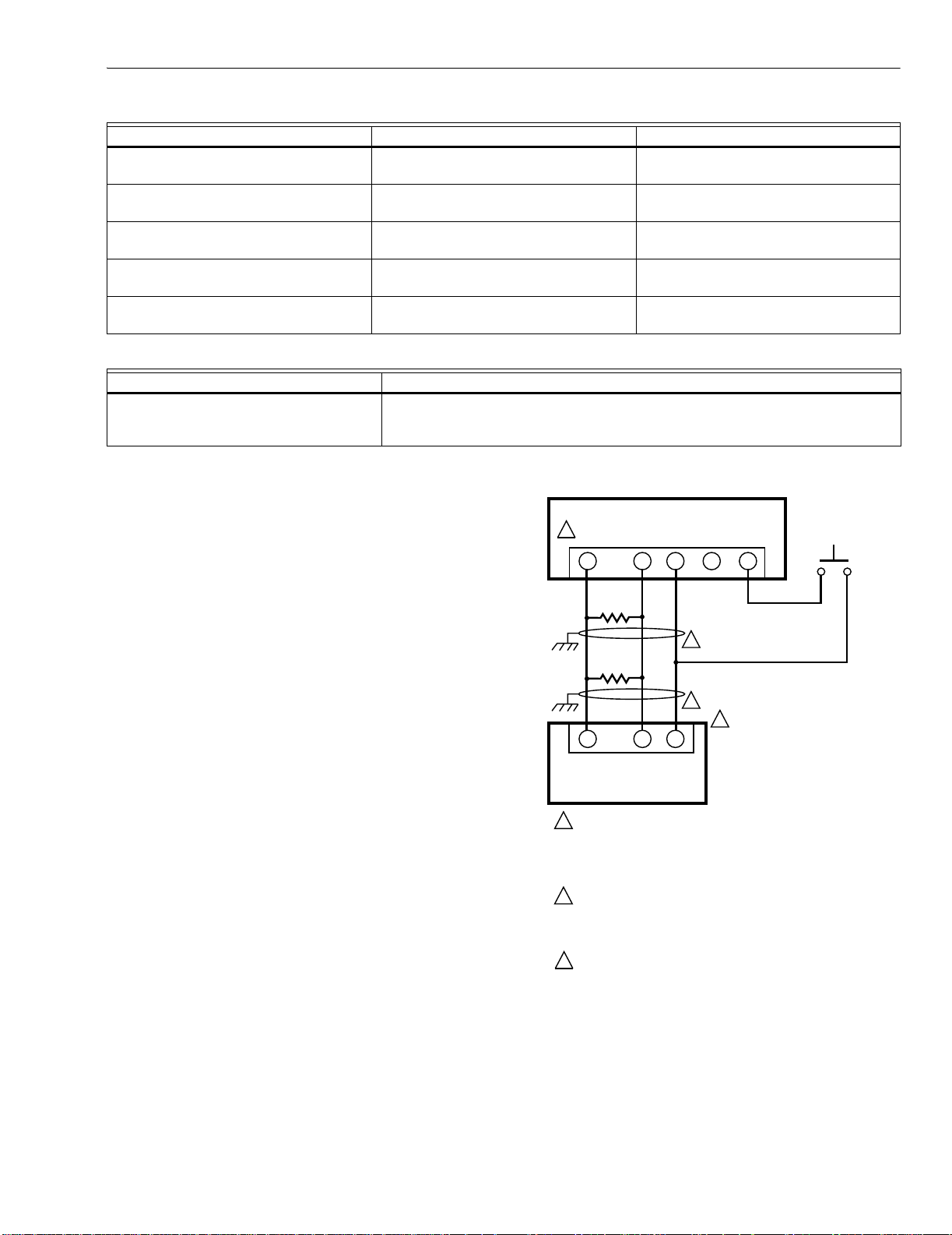
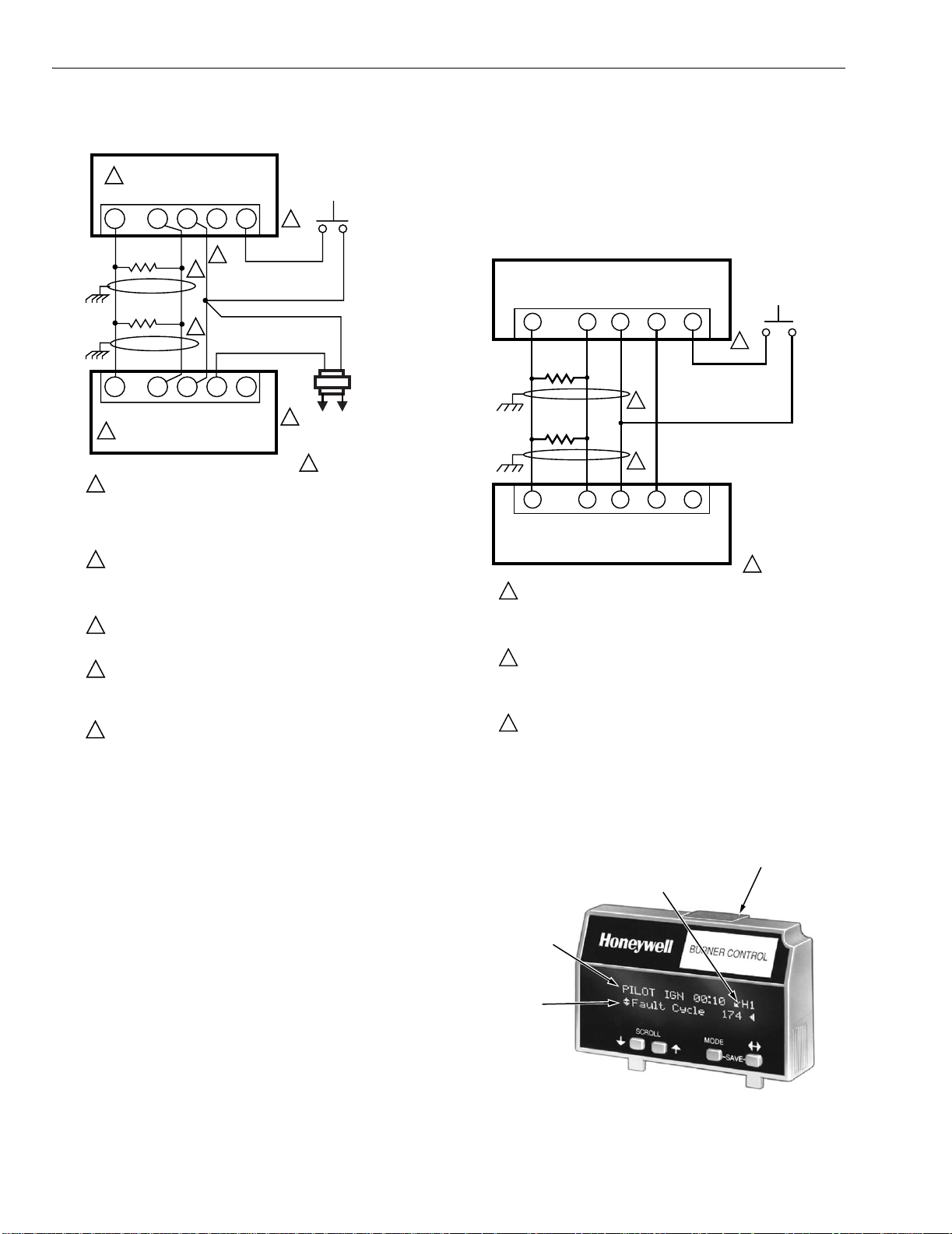
1. Refer to Fig. 5, 6, and 7 for proper wiring.
2. Make sure all wiring complies with all applicable
electrical codes, ordinances and regulations.
3. For recommended wire size and type, see Table 1.
4. For Recommended grounding practices, see Table 2.
5. For KDM: The KDM is powered from a low voltage,
energy-limited source. It can be mounted outside of a
control panel if it is protected from mechanical damage.
NOTE: A 13 Vdc power supply must be used any time more
than one KDM is used. A maximum of two KDM,
Data ControlBus Modules™ or S7810B Multi-Drop
Switch Modules are allowed in any combination.
65-0090—4 4
Page 5
7800 SERIES S7800A KEYBOARD DISPLAY MODULE
N
Table 1. Recommended Wire Size and Part Number.
Application Recommended Wire Size Recommended Part Number
Keyboard Display Module 22 AWG two-wire twisted pair with
ground, or five-wire.
Data ControlBus™ Module 22 AWG two-wire twisted pair with
ground, or five-wire.
Remote Reset Module 22 AWG two-wire twisted pair, insulated
for low voltage.
Communications Interface ControlBus
Module™
13 Vdc full wave rectified transformer
power input.
22 AWG two-wire twisted pair with
ground.
18 AWG wire, insulated for voltages and
temperatures for given applications.
Table 2. Recommended Grounding Practices.
Ground Type Recommended Practice
Signal ground (KDM, Data ControlBus™
Module, Communications Interface
Use the shield of the signal wire to ground the device to the signal ground terminals
[3(c)] of each device. Connect the shield at both ends of the daisy chain to ground.
ControlBus Module™).
6. Recommended wire routing:
a. ControlBus:
(1) Do not route the ControlBus cable in conduits
S7800 KEYBOARD DISPLAY MODULE
(MOUNTED ON 7800 SERIES RELAY MODULE)
that carry line voltage circuits.
(2) Avoid routing the ControlBus cable close to
ignition transformer leadwires.
(3) Route the ControlBus cable outside of conduit if
properly supported and protected from damage.
3
A
1
b. Remote Reset:
(1) Do not run high voltage ignition transformer
wires in the same conduit with the Remote Reset
120 OHM
RESISTOR
wiring.
(2) Do not route Remote Reset wires in conduit with
line voltage circuits.
7. Maximum wire lengths:
120 OHM
RESISTOR
a. KDM: The maximum length interconnecting wire is
4000 ft (1219m).
b. Remote Reset leadwires: The maximum length wire
is 1000 ft (300m) to a Remote Reset push-button.
8. Install all electrical connectors.
9. Restore power to the panel.
1
A
Belden 8723 shielded cable or equivalent.
Belden 8723 shielded cable or equivalent.
—
Belden 8723 shielded cable or equivalent.
TTW60C, THW75C, THHN90C
MOMENTARY
PUSH BUTTO
B
C (GND)
23
1
1
23
B
C
RESET
+13 VDC
4
5
2
QS7800 COMMUNICATIONS
INTERFACE CONTROLBUS
MODULE, MOUNTED IN
Q7700 COMMUNICATIONS
INTERFACE MODULE
SWITCH
THREE WIRE SHIELDED CABLE MAY BE REQUIRED. TWO 120
1
OHM TERMINATING RESISTORS ARE REQUIRED FOR
CONNECTIONS OVER 100 FEET (30 METERS). CABLE SHIELD
MUST BE TERMINATED TO EARTH GROUND AT BOTH ENDS.
IF SHIELDED CABLE IS NOT USED, TWISTED PAIR
WIRE MUST BE USED.
2
WHEN CONNECTING THE KEYBOARD DISPLAY MODULE, DATA
CONTROLBUS MODULE“, OR REMOTE RESET MODULE
EXTERNAL FROM THE CONTROL CABINET, APPROPRIATE
MEASURES MUST BE TAKEN TO MEET EN60730 SAFETY
LOW VOLTAGE REQUIREMENTS (SEE APPROVALS).
TERMINALS OF 203541 5-WIRE CONNECTOR.
3
M1990F
Fig. 5. Wiring the keyboard display module.
5 65-0090—4
Page 6
7800 SERIES S7800A KEYBOARD DISPLAY MODULE
,
N
S
M
P
M
sequence status information. It also replaces a selectable
S7800 KEYBOARD DISPLAY MODULE
(MOUNTED ON 7800 SERIES RELAY MODULE)
message after 60 seconds if it or a lockout message is
available. The 7800 SERIES Relay Module LED provide
positive visual indication of the Relay Module sequence. The
5
A
B
C (GND)
23 54
1
120 OHM
RESISTOR
120 OHM
RESISTOR
1
A
5
S7800 REMOTE KEYBOARD DISPLAY MODULE
1
THREE WIRE SHIELDED CABLE MAY BE REQUIRED. TWO
120 OHM TERMINATING RESISTORS ARE REQUIRED FOR
CONNECTING OVER 100 FEET [30 METERS]. CABLE SHIELD
MUST BE TERMINATED TO EARTH GROUND AT BOTH ENDS.
IF SHIELDED CABLE IS NOT USED, TWISTED PAIR WIRE
MUST BE USED.
2
WHEN CONNECTING THE KEYBOARD DISPLAY MODULE DATA
CONTROLBUS MODULE“, OR REMOTE RESET MODULE
EXTERNAL FROM THE CONTROL CABINET, APPROPRIATE
MEASURES MUST BE TAKEN TO MEET EN60730 SAFETY
LOW VOLTAGE REQUIREMENTS (SEE APPROVALS).
3
7800 SERIES RELAY MODULE CAN SUPPORT ONE S7800
KEYBOARD DISPLAY MODULE. A 13 Vdc POWER SUPPLY
IS REQUIRED FOR EACH ADDITIONAL DISPLAY.
4
UP TO 36 S7800 KEYBOARD DISPLAYS CAN BE CONNECTED
TO A SINGLE 7800 RELAY MODULE NOT TO EXCEED
4000 FEET (1219M) TOTAL LEADWIRE RUN. DAISY CHAIN 1 TO 1
2 TO 2, 3 TO 3 AND PROVIDE 13 Vdc POWER SUPPLY FOR
EACH S7800 DISPLAY.
5
TERMINALS OF 203541 5-WIRE CONNECTOR.
1
1
23 54
B
C (GND)
+13 VDC
2
+13 VDC
RESET
RESET
Fig. 6. Wiring for multiple keyboard display modules.
MOMENTARY
PUSHBUTTON
SWITCH
3
4
2
L1
(HOT)
L2
13 Vdc
POWER
SUPPLY
M5006G
LED is energized simultaneously with the correct sequence
description.
S7810 DATA CONTROLBUS MODULE™
(MOUNTED ON 7800 SERIES RELAY MODULE)
MOMENTARY
PUSH BUTTO
A
1
120 OHM
RESISTOR
120 OHM
RESISTOR
1
A
7800 REMOTE KEYBOARD DISPLAY MODULE
THREE WIRE SHIELDED CABLE MAY BE REQUIRED. TWO 120
1
OHM TERMINATING RESISTORS ARE REQUIRED FOR
CONNECTIONS OVER 100 FEET. CABLE SHIELD MUST BE
TERMINATED TO EARTH GROUND AT BOTH ENDS. IF SHIELDED
CABLE IS NOT USED, TWISTED PAIR WIRE MUST BE USED.
2
WHEN CONNECTING THE KEYBOARD DISPLAY MODULE DATA
CONTROLBUS MODULE™, OR REMOTE RESET MODULE
EXTERNAL FROM THE CONTROL CABINET, APPROPRIATE
MEASURES MUST BE TAKEN TO MEET EN60730 SAFETY
LOW VOLTAGE REQUIREMENTS (SEE APPROVALS).
3
221818A OR C EXTENSION CAN BE USED IN PLACE OF THE
S7810 DATA CONTROLBUS MODULE™ IF DISPLAY IS TO
A CABINET DOOR.
B
C (GND)
23
1
1
23
B
C (GND)
+13 VDC
4
4
+13 VDC
RESET
5
5
RESET
SWITCH
3
2
M5285C
Fig. 7. Wiring keyboard display module
for remote mounting.
KDM Display
The first line of the KDM display provides current status of the
burner sequence (STANDBY, PURGE, PILOT IGN, MAIN
IGN, RUN and POSTPURGE), timing information (PURGE,
PILOT IGN, MAIN IGN and POSTPURGE) in minutes and
seconds, hold information (PURGE HOLD), and lockout
DI = DIAGNOSTICS
H1 = HISTORY
EA = EXPANDED ANNUNCIATOR
information (Lockout, Fault Code, Message and Sequence),
see Fig. 8. The extreme right side of the first line will be either
blank or will show a small arrow pointing to the second line
followed by a two-letter code (DI—Diagnostic Information,
Hn—Fault History Information (where n equals the number of
the fault), and EA—Expanded Annunciator). When the arrow
and two-letter code are displayed, it indicates the second line
is showing a selectable message submenu. The second line
SEQUENCE
STATUS
ELECTABLE
ESSAGE OR
REEMPTIVE
ESSAGE
will display selectable or preemptive messages. A selectable
message supplies information for flame strength, system
status indication, system or self-diagnostics and
troubleshooting. A preemptive message has parentheses
around the message and supplies a detailed message to
support the sequence status information. A preemptive
message can also be a lockout message. A preemptive
message replaces a selectable message to support the
Fig. 8. S7800 Keyboard Display Module.
FIVE WIRE CONNECTOR FOR
COMMUNICATIONS, REMOTE KEYBOARD
DISPLAY AND REMOTE RESET
M7412
65-0090—4 6
Page 7
7800 SERIES S7800A KEYBOARD DISPLAY MODULE
Keyboard Functions
The keyboard contains four push-buttons with separate
functions (SCROLL-down, SCROLL-up, MODE, and
CHANGE-LEVEL). The MODE and CHANGE-LEVEL, when
pressed together, provide a SAVE function.
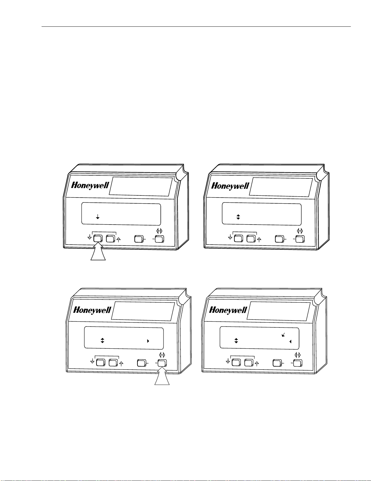
1. SCROLL down-up push-buttons (↕). See Fig. 9. The
SCROLL down-up push-buttons (↕) are used to scroll
through the selectable messages. The double-headed
arrow (↕), which is located in the lower left position of
the second line of the display, represents the SCROLL
down-up push-buttons. The SCROLL down-up pushbuttons (↕) can be pressed to display the selectable
messages one at a time or held down to scroll through
the selectable messages at the rate of two per second.
BURNER CONTROL
RUN
Total Cycles 333
When the last item of the selectable message is viewed,
the display wraps around and displays the first
selectable message again.
2. CHANGE-LEVEL push-button (
↔), see Fig. 10. The
CHANGE-LEVEL push-button is used to change
between the first hierarchy of selectable messages to a
subset of selectable messages. The CHANGE-LEVEL
push-button can also be used to change from a subset
message to a first level selectable message. The
symbol (<), located on the second line in the lower right
corner of the display, represents a subset of selectable
messages.
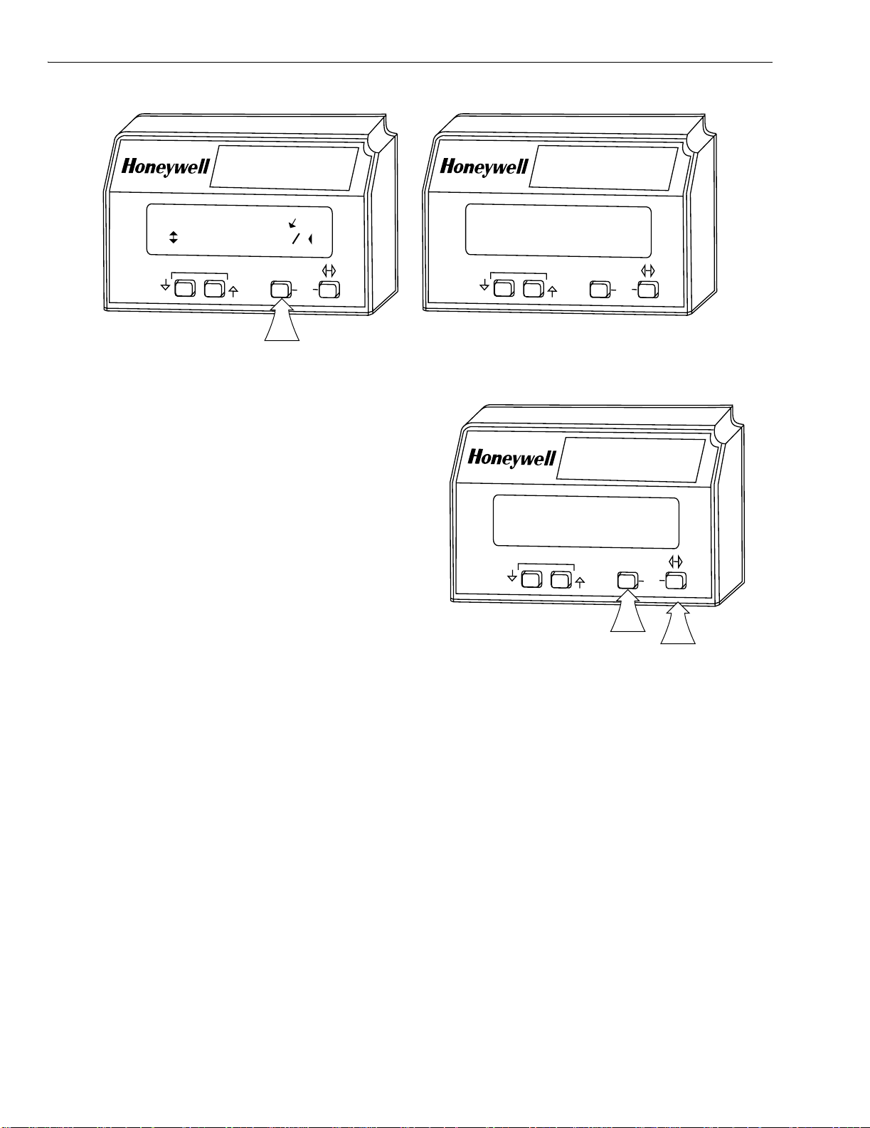
3. MODE push-button, see Fig. 11. Use the MODE
push-button to instantaneously switch the display from a
second-line selectable message to a second-line
preempted message. The sixty second time-out
function can also be used for this task. The MODE
push-button only works if there is a second-line
preempted message or a lockout message.
BURNER CONTROL
RUN
Total Hours 1332
SCROLL
MODE
BURNER CONTROL
PILOT IGN 00:05
Fault History
SCROLL
MODE
Fig. 10. CHANGE-LEVEL (
SAVE
Fig. 9. SCROLL (↕
SAVE
SCROLL
) push-button function.
PILOT IGN 00:10 H1
Fault Cycle 174
SCROLL
↔) push-button function.
MODE
SAVE
M1932A
BURNER CONTROL
MODE
SAVE
M1933A
7 65-0090—4
Page 8
7800 SERIES S7800A KEYBOARD DISPLAY MODULE
A
BURNER CONTROL
LOCKOUT 17 DI
Main Valve T9 = O
SCROLL
MODE
SAVE
Fig. 11. MODE push-button function.
4. SAVE function, see Fig. 12. The SAVE function enables
users to identify the selectable message they want to
view upon power restoration. The second line
selectable message are restored to the most recently
saved selection when power returns. The SAVE
function is performed is by pressing and holding the
MODE key and then pressing the CHANGE-LEVEL key
(´). The second line of the display briefly notes
“…SAVING…” to confirm the keys were pressed.
Selectable Messages
For the second line display, two-level hierarchy, see Table 3.
The display values are as follows:
BURNER CONTROL
LOCKOUT 17
*Main Flame Fail*
SCROLL
MODE
BURNER CONTROL
PURGE 00:30
... SAVING ...
SCROLL
SAVE
M1934C
MODE
SAVE
n represents a numbered value.
T represents the terminal number.
x represents the suffix letter of the Relay Module.
M1935
Fig. 12. SAVE function.
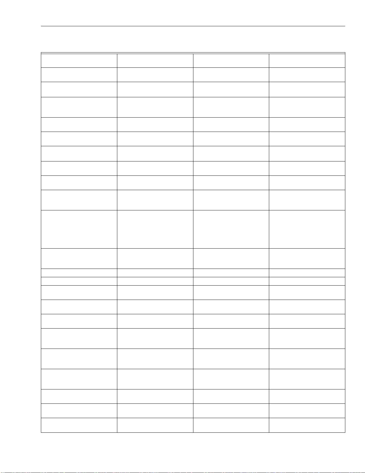
Table 3. Selectable Messages.
65-0090—4 8
Page 9
7800 SERIES S7800A KEYBOARD DISPLAY MODULE
Table 3. Selectable Messages .
Selectable
Message/Display
Description
↕Flame Signal Flame signal strength. 0 - 5.0 Vdc Flame Amp (+ and
↕Total Cycles Total number of equipment
operating cycles.
↕Total Hours Total number of equipment
operating hours.
Possible States/ Range
(Terminals)
- (Com))
0 - 99,999
(250,000) cycles
a
0 - 99,999
(250,000) hours
a
Comments
Flame relay pull-in and dropout value 1.25 Vdc.
Cycle will be updated each
time main valve is energized.
Hour will be updated each time
main valve output is energized
for 60 minutes.
↕Fault History >
(Six most recent faults)
Fault Cycle !
H1
Fault Hours !
H1
Fault Code !
H1
*Fault Message* !
First level prompt for history
— —
information. Has subset level.
Cycle when fault occurred. 0 - 99,999 cycles (250,000)
—
cycles
Run hour when fault occurred. 0 - 99,999
(250,000) hours
Number that identifies the
0 - 999 —
a
—
reason for lockout.
Indicates cause of lockout. — —
H1
Sequence Message !
H1
Indicates where in the
sequence the lockout
— —
occurred.
(Second Line Message) !
H1
Second line message explains
any further information that is
— —
available from the 7800
SERIES or may be blank if
there is not a preemptive
second-line. H2…H6 etc.
Diagnostic Information > First level prompt for
— —
diagnostic information. Has
subset level.
Device Device type number. RM78XXX or EC78XXX —
Device Suffix Device suffix number. nnnn —
Run/Test Sw. Position of Run/Test Switch. RUN or TEST Indicates if 7800 SERIES is in
RUN or TEST mode.
OperControl T6 Operating Control Input. = 1 or 0 Indicates if input is on or off,
energized or de-energized.
Interlock T7 Running/Lockout Interlock. = 1 or 0 Indicates if input is on (1) or off
(0), energized or de-energized.
Pilot Valve T8 Pilot Valve. = 1 or 0 Indicates if output terminal is
on or off, energized or
de-energized.
Main Valve T9 Main Fuel Valve. = 1 or 0 Indicates if output terminal is
on or off, energized or
de-energized.
Ignition T10 Ignition. = 1 or 0 Indicates if output terminal is
on or off, energized or deenergized.
LowFire Sw T18 Low Fire Switch. = 1 or 0 Indicates if input is on or off,
energized or de-energized.
HighFireSw T19 High Fire Switch. = 1 or 0 Indicates if input is on or off,
energized or de-energized.
PreIgn ILK
T20 or T17b Preignition
Interlock
= 1 or 0 Indicates if input is on or off,
energized or de-energized.
9 65-0090—4
Page 10
7800 SERIES S7800A KEYBOARD DISPLAY MODULE
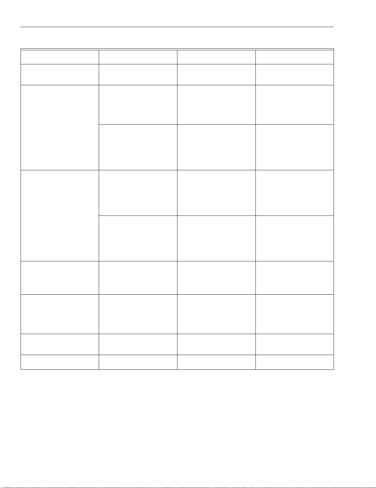
Table 3. Selectable Messages (Continued).
Selectable
Message/Display
Val v/Start T21 Interrupted/Intermittent
Pilot Valve, First Stage Oil
Valve or Start Input.
Jumper 1 Pilot Flame Establishing
Period (PFEP).
First Safety Time (for RM/
EC7850).
Jumper 2 Pilot Valve. INTACT/CLIPPED Display shows state of Pilot
Main Trial Time (for RM/
EC7850).
Jumper 3 Start-up Airflow Switch (AFS)
check.
Amp Type Defines type of amplifier
installed.
Flame Response Amplifier Flame Failure
Response Time (FFRT) in
seconds.
Purge Time Timing value of purge card. mm:ss Two seconds to 30 minutes.
Description
Possible States/ Range
(Terminals)
= 1 or 0 Indicates if output is on or off,
energized or de-energized.
INTACT/CLIPPED Display shows state of PFEP
jumper. If jumper is intact,
7800 SERIES was 10 second
PFEP. If jumper is clipped,
7800 SERIES has 4 second
PFEP.
INTACT/CLIPPED Display shows state of First
Safety Time (EC7850) jumper.
If jumper is intact, EC7850 has
5 second First Safety Time. If
jumper is clipped, the EC7850
has 3 second First Safety
Time.
Valve (terminal no. 21). If
jumper is intact, RM7800G has
Intermittent Pilot Valve. If
jumper is clipped, RM7800G
has 15 or 30 second
Interrupted Pilot Valve.
INTACT/CLIPPED Display shows state of Main
INTACT Disabled/CLIPPED
Enabled
STANDARD/AMP-CHECK/
SHUTTER
.8s, 1s, 2s, or 3s —
Trial Time (EC7850)Valve
(terminal no. 21). If jumper is
intact, EC7850 has 5 second
Main Trial Time. If jumper is
clipped, EC7850 has 3 second
Main Trial Time.
Display shows state of Start-up
AFS check jumper. If jumper is
clipped, RM7800 AFS check is
enabled and if jumper is intact,
AFS check is disabled.
Display shows type of flame
detection system installed (i.e.,
as STANDARD, AMP-CHECK/
AMPLI-CHECK™ and
SHUTTER/ Dynamic SelfChecking).
Comments
a
European Approved Controls.
b
Preignition Interlock Terminal 17 or 20 is model dependent.
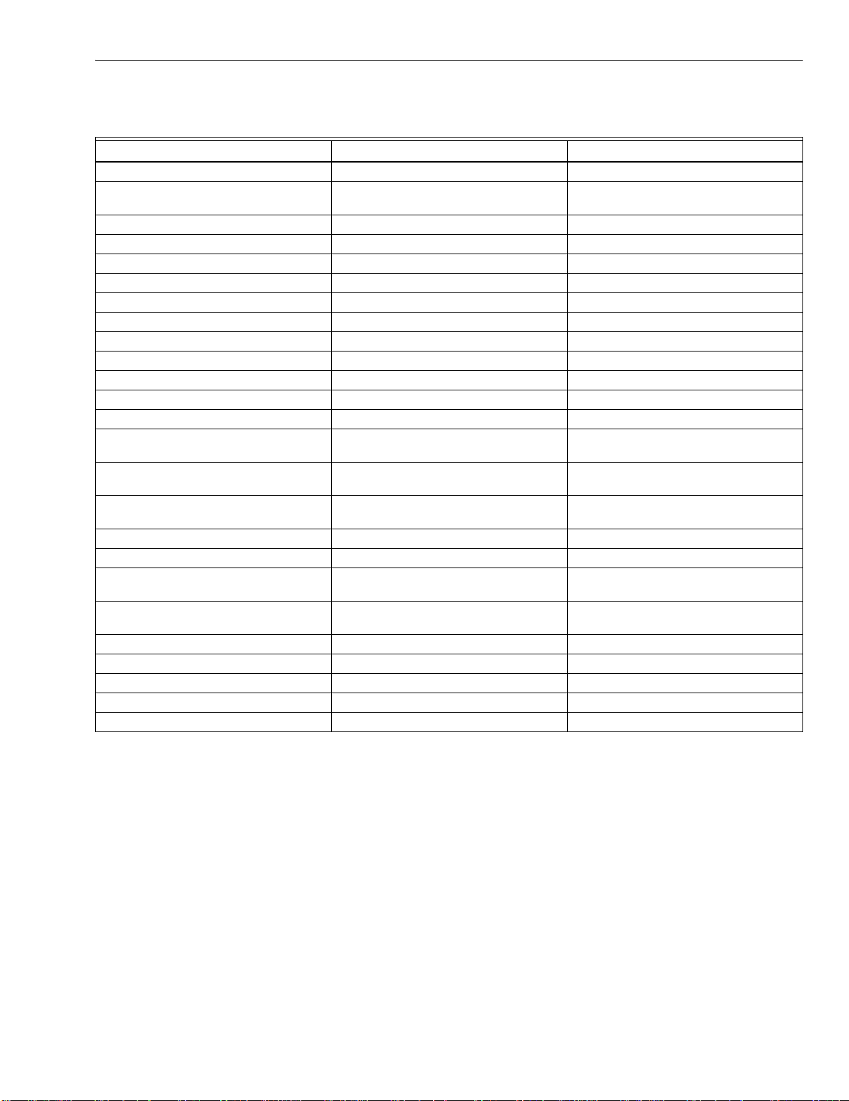
Expanded Annunciator Messages (Table 4)
The Expanded Annunciator (EA) may or may not be
connected because it is an optional device. If the EA is not
connected, a display message of “(EA not connected)” is
65-0090—4 10
shown. If the EA is connected, display messages are shown;
see Table 4 (Note that 1 means ON and 0 means OFF). When
accessing Expanded Annunciator messages, follow the same
operations as used with the Selectable messages.
Page 11
7800 SERIES S7800A KEYBOARD DISPLAY MODULE
Table 4. Expanded Annunciator.
Selectable Message
↕Expanded Annunciator↔
↕Expanded Annunciator (EA not
connected)<
↕Current Status (CS:)
↕Valve Closure (Valve Close) T5 = 1 or 0< "EA
↕Burner Switch (Burner Sw.) T5 = 1 or 0< "EA
↕Operating Control (OperControl) T6 = 1 or 0< "EA
↕Auxiliary Limit (Aux Limit 1) T7 = 1 or 0< "EA
↕Auxiliary Limit (Aux Limit 2) T8 = 1 or 0< "EA
↕Low water Cutoff (LWCO) T9 = 1 or 0< "EA
↕High Limit (High Limit) T10 = 1 or 0< "EA
↕Auxiliary Limit (AuxLimit 3) T11 = 1 or 0< "EA
↕Oil Selection Switch (Oil Select) T12 = 1 or 0< "EA
↕High Oil Pressure Switch (Hi OilPres) T13 = 1 or 0< "EA
↕Low Oil Pressure Switch
(LowOilPres)
↕High Oil Temperature Switch (Hi
OilTemp)
↕Low Oil Temperature Switch
(LowOilTemp)
↕Atomizing Switch (Atomize Sw) T19 = 1 or 0 "EA
↕Gas Selection Switch (Gas Select) T17 = 1 or 0< "EA
↕High Gas Pressure Switch (Hi
GasPres)
↕Low Gas Pressure Switch
(LowGasPres)
↕Airflow Switch (Airflow Sw) T20 = 1 or 0< "EA
↕Auxiliary Interlock (Aux ILK 4) T21 = 1 or 0< "EA
↕Auxiliary Interlock (Aux ILK 5) T22 = 1 or 0< "EA
↕EA Fault Code nnn< "EA
↕Software Revision (SW Rev.) nnnn< "EA
a
(Second Line) Display Value (Second Line) First Line Message
a
EA Message< "EA
T14 = 1 or 0< "EA
T15 = 1 or 0< "EA
T16 = 1 or 0< "EA
T18 = 1 or 0< "EA
T19 = 1 or 0< "EA
"EA
TROUBLESHOOTING
After the KDM is installed, return the 7800 SERIES to normal
operation, restore power and run the system through at least
one complete automatic cycle. For complete Troubleshooting
and System Checkout information, see form 65-0229.
7800 SERIES System Diagnostics
Troubleshooting control system equipment failures is made
easier with the 7800 SERIES self-diagnostics and first-out
annunciation. The S7800 provides visual annunciation by
displaying a fault code and fault or hold message on the
display.
11 65-0090—4
Self-diagnostics of the 7800 SERIES enables it to detect and
annunciate both external and internal system problems.
Internal faults and external faults such as interlock failures,
flame failures and false flame signals are annunciated by the
KDM via the 7800 SERIES Relay Module.
The KDM displays a sequence status message indicating
STANDBY, PREPURGE, PREIGNITION, SAFETY 1, PILOT
IGN, PILOT STAB., MAIN IGN, RUN or POSTPURGE, as
appropriate. The selectable messages also provide visual
indication of current status and historical status of the
equipment, such as: Flame Signal, Total Cycles, Total Hours,
Fault History, Diagnostic Information and Expanded
Annunciator terminal status (if used). With this information,
most problems can be diagnosed without extensive
trial-and-error testing.
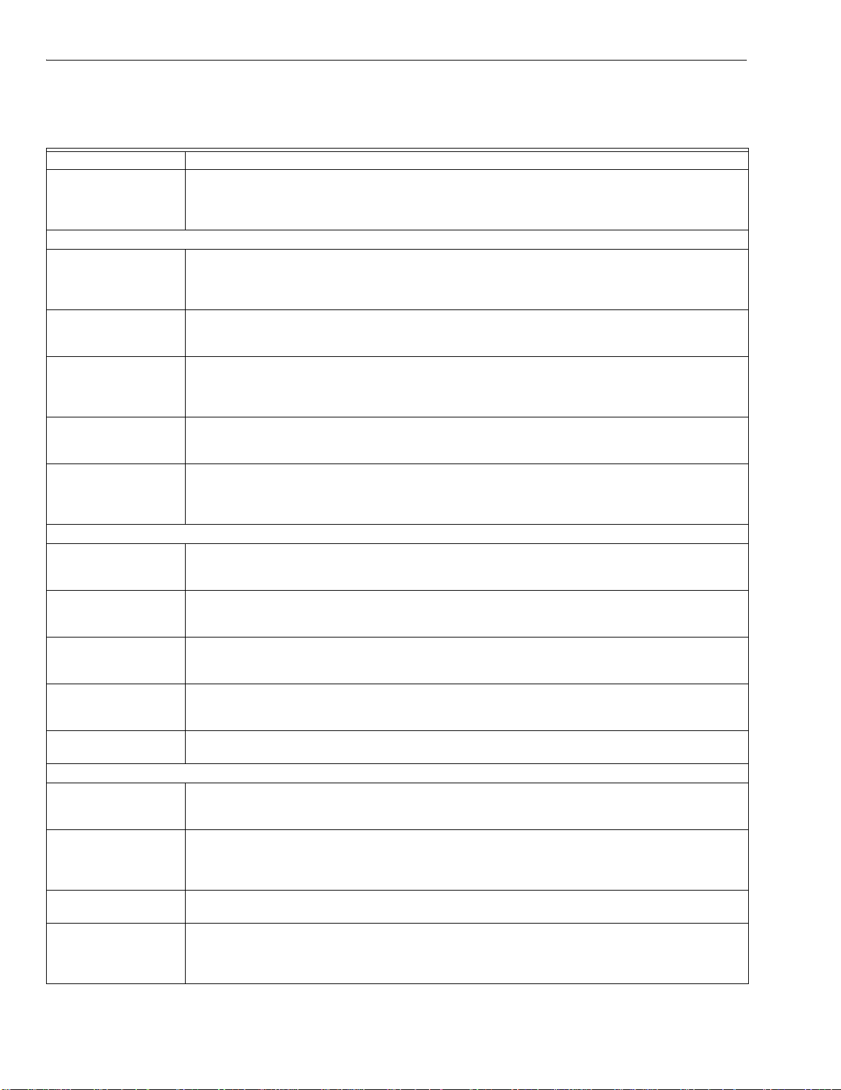
Table 5 provides the sequence and status hold messages.
Page 12
7800 SERIES S7800A KEYBOARD DISPLAY MODULE
Table 5. Keyboard Display Module Sequence and Status Hold Messages .
Sequence Status
INITIATE mm:ss The Keyboard Display Module (KDM) indicates the burner status, INITIATE, a stabilization period for
the relay module to check for any fluctuations in ac line voltage inputs or control inputs on power up or
during normal operation. The timing of the INITIATE period is either two seconds or ten seconds,
depending on the model, before entering STANDBY.
If the relay module is in an INITIATE HOLD status, the following conditions could exist:
INITIATE HOLD:
(AC Frequency/Noise)
The KDM indicates the burner status and that it is waiting for excess line noise to clear up, which
prevents sufficient reading of the line voltage inputs. The burner sequence does not advance into
STANDBY until the excess line noise ceases or a line frequency error occurs; this is caused by using a
60 Hz device on a 50 Hz line, or vice versa on devices with a date code earlier than 9804, is corrected.
INITIATE HOLD:
(AC Line Dropout)
The KDM indicates the burner status and that ac line power has momentarily dropped out. The burner
sequence does not advance into STANDBY until the ac line voltage has stabilized throughout the
INITIATE sequence.
INITIATE HOLD:
(AC Frequency)
The KDM indicates the burner status and that line frequency is faster than the expected value. The
burner sequence does not advance into STANDBY until the line frequency returns to the proper value;
this is perhaps caused by using a 60 Hz device on a 50 Hz line for devices with a date code earlier
than 9804.
INITIATE HOLD:
(Low Line Voltage)
The KDM indicates the burner status and that low line voltage (10% lower than rated voltage) has
occurred. The burner sequence does not advance into STANDBY until the line voltage is at a sufficient
level for proper operating parameters.
STANDBY The KDM indicates the burner status, STANDBY. The burner can be placed in STANDBY by opening
the burner switch or if the operating controller indicates its setpoint is satisfied. If a demand is present
for burner operation, the burner sequence does not advance from STANDBY to PURGE until the
recycle limits close. If an Expanded Annunciator is connected, the display messages are enhanced.
If the relay module is in a STANDBY HOLD status, the following conditions could exist:
STANDBY HOLD:
F/G (Flame Detected)
The KDM indicates the burner status and that a flame is detected. A demand is present for burner
operation. The sequence does not advance to PREPURGE until the flame signal clears. If the flame
signal does not clear within 40 seconds, the relay module locks out.
STANDBY HOLD: T20
(Preignition Interlock)
The KDM indicates the burner status and that the Preignition Interlock is not closed. A demand is
present for burner operation, but the burner sequence does not advance to PREPURGE until the
Preignition Interlock proves closed. If this time exceeds a 30 second hold, the relay module locks out.
STANDBY HOLD: T7
(Lockout Interlock)
The KDM indicates the burner status and that the Lockout Interlock is closed. A demand is present for
burner operation, but the burner sequence does not advance to PREPURGE until the Lockout
Interlock proves open. If this time exceeds the 120 second hold, the relay module locks out.
STANDBY HOLD: T7
(Running Interlock)
EC/RM7850
The KDM indicates the burner status and that the Running Interlock is closed. A demand is present for
burner operation, but the burner sequence does not advance to PREPURGE until the Running
Interlock proves open. If this time exceeds the 120 second hold, the relay module locks out.
PURGE The KDM indicates the burner status, PURGE, which is the period of time the blower motor is running
before the Ignition period. The timing of the PURGE period is selectable.
If the relay module is in a PURGE HOLD status, the following conditions could exist:
PURGE HOLD: T19
(High Fire Switch)
The KDM indicates the burner status and that the High Fire Switch is not closed. The firing rate motor
is driving to its PURGE rate position. If this time exceeds four minutes and fifteen seconds, the relay
module locks out.
PURGE DELAY: T19
(High Fire Switch
Jumpered)
The KDM indicates the burner status and that the High Fire Switch is jumpered. The High Fire Switch
is bypassed, welded or otherwise prematurely closed. The system automatically adds 30 seconds to
allow the firing rate motor additional drive time to reach or near the open damper position before
starting the PURGE sequence.
PURGE HOLD: TEST
(Run/Test Switch)
PURGE HOLD: T18
(Low Fire Switch
Jumpered)
The KDM indicates the burner status and that the Run/Test Switch is in the TEST position. The
sequence does not continue until the Run/Test Switch is placed in the RUN position.
The KDM indicates the burner status and that the Low Fire Switch is jumpered. The Low Fire Switch is
bypassed, welded or otherwise prematurely closed. The system automatically adds 30 seconds to
allow the firing rate motor additional drive time to reach or near the closed damper position before
starting the ignition sequence.
65-0090—4 12
Page 13
7800 SERIES S7800A KEYBOARD DISPLAY MODULE
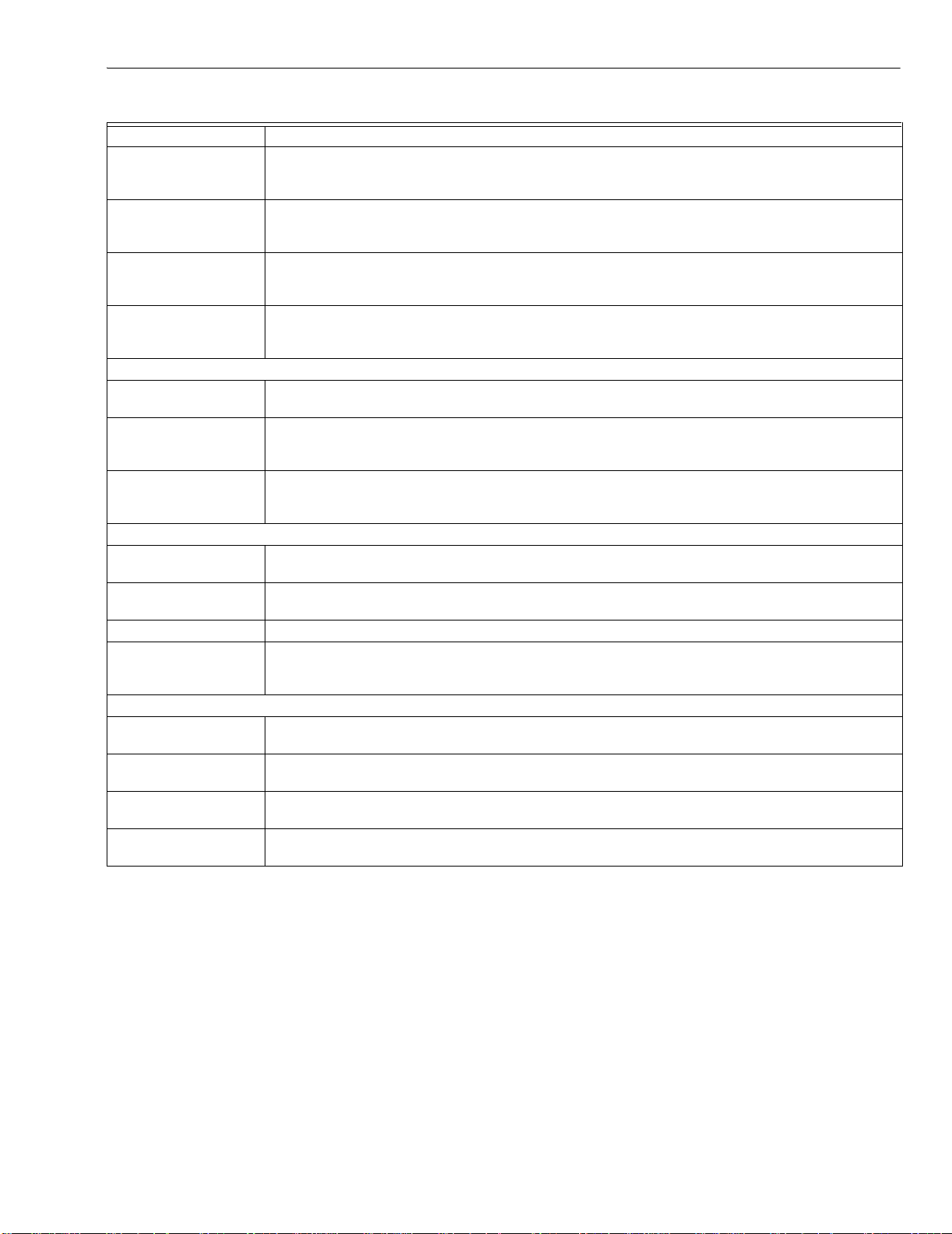
Table 5. Keyboard Display Module Sequence and Status Hold Messages (Continued).
Sequence Status
PURGE HOLD: F/G
(Flame Detected)
PURGE HOLD: T18
(Low Fire Switch)
PURGE HOLD: T7
(Running Interlock)
PILOT IGN mm:ss The KDM indicates the burner status, PILOT IGN, and the timing of the PILOT IGN trial begins, in
If the relay module is in a PILOT HOLD status, the following conditions could exist:
PILOT HOLD: TEST
(Run/Test Switch)
MAIN IGN mm:ss The KDM indicates the burner status, MAIN IGN, and the timing of the MAIN IGN trial begins, in
RUN The KDM indicates the burner status, RUN, which is the period of time after the Ignition Trials and
If the relay module is in a RUN HOLD status, the following condition could exist:
RUN LOWFIRE: TEST
(Run/Test Switch)
POSTPURGE mm:ss The KDM indicates the burner status, POSTPURGE, which is the period of time after the RUN period
Waiting for connection... The KDM has power but is waiting to receive a signal from the relay module to continue operation.
RESET/ALARM TEST The KDM indicates the burner status, RESET/ALARM TEST. This condition indicates that the reset
Additional Sequence Status Information When An Expanded Annunciator is Connected to the Relay Module:
BURNER OFF: T6
(Burner Switch)
STANDBY The KDM indicates the burner status, STANDBY, and that the Operating Control is not closed. The
STANDBY HOLD: T6
(EA Hold Message)
STANDBY HOLD: T6
(Circuit Fault)
The S7800 provides diagnostic information to aid the service
mechanic in obtaining information when troubleshooting the
system. See Table 6 for information on accessing historical
and diagnostic selectable messages. Information available in
the Diagnostic Information includes Device Type, Device
Suffix, Software Revision, Manufacturing Code, Flame
Amplifier Type, Flame Failure Response Time (FFRT),
Selectable Jumper Configuration Status, Run/Test Switch
Status and Terminal Status.
The KDM indicates the burner status and that a flame is detected. The burner sequence does not
advance through PREPURGE because a flame is detected as being present. The sequence holds
waiting for the flame signal to clear. If the time exceeds 30 seconds, the relay module locks out.
The KDM indicates the burner status and that the Low Fire Switch is not closed. The firing rate motor is
driving to its Low Fire position in preparation for Ignition Trials. If this time exceeds four minutes and
fifteen seconds, the relay module locks out.
The KDM indicates the burner status and that the Running Interlock is not closed. The sequence does
not advance to ignition until the Running Interlock proves closed. If this time exceeds 30 seconds, the
relay module locks out.
seconds. During this period, the relay module permits the pilot valve to open and the pilot flame to
establish.
The KDM indicates the burner status, PILOT IGN, and that the Run/Test Switch is in the TEST position.
The sequence does not continue until the Run/Test Switch is placed in the RUN position.
seconds. During this period, the relay module permits the main valve to open and the main flame to
establish.
before the operating controller setpoint is reached. During this time, the burner is firing under control of
the firing rate control.
The KDM indicates the burner status and that the Run/Test Switch is in the TEST position. Normal
modulation or operation does not continue until the Run/Test Switch is placed in the RUN position.
when the blower motor continues to run. The timing of the POSTPURGE period is fifteen seconds.
button is pressed. If it is held for more than four seconds, the alarm output is energized. The alarm
output is de-energized when the reset button is released.
The KDM indicates the Burner Switch is not closed. The burner sequence does not advance to
PREPURGE until the Burner Switch closes.
burner sequence does not advance to PREPURGE until the Operating Control closes.
The KDM indicates the burner status, STANDBY, and that a limit is not closed. The burner sequence
does not advance to PREPURGE until one or all limits close downstream from the Operating Control.
The KDM indicates the burner status, STANDBY, and that the control input is not closed. The burner
sequence does not advance to PREPURGE until the control input closes.
Historical Information Index
The S7800 displays historical information for the six most
recent lockouts. Each of the six lockout records retains the
cycle when the fault occurred, a fault code, a fault message,
and burner status when the fault occurred. See Table 6.
13 65-0090—4
Page 14
7800 SERIES S7800A KEYBOARD DISPLAY MODULE
C
A
C
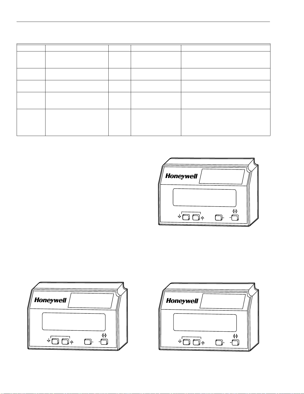
Table 6. Accessing Historical and Diagnostic Selectable Messages.
Step Operation Press Display Comments
1. Press SCROLL key to access
Diagnostic Information.
(↕) STANDBY
↕Diagnostic Info>
Use the Down/Up SCROLL keys to access
the selectable message. The second line
will display Diagnostic Information.
2. Press Change Level key to
Access Diagnostic Information.
3. Continue display of Diagnostic
Information.
4. Continue through remaining
(↔) STANDBY
↕Diagnostic Info>
(↕) STANDBY ! DI
↕Device RM7800<
Use the Change Level key to access the
Diagnostic Information.
Push the (↕) SCROLL key to scroll to the
next Diagnostic Message.
— — —
Diagnostic Information display
following step 3 as required.
5. Press the Change Level key to
return to the first level of
Diagnostic Information data
(↔) STANDBY
↕Diagnostic Info>
Another display can be selected or
discontinue accessing Diagnostic
Information review.
prompt or to other selectable
messages.
SERVICE NOTE: If the Keyboard Display Module screen is
scrambled, remove and reinstall the Keyboard
Display Module and reset the 7800 SERIES Relay
Module.
SERVICE NOTE: Reset the 7800 SERIES Relay Module by
pressing the reset pushbutton on the relay module or
pressing a remote reset pushbutton wired through
the Keyboard Display Module, Data ControlBus™
Module or Remote Reset Module. A power-up reset
will cause an electrical reset of the 7800 SERIES
Relay Module but will not reset a lockout condition.
Lockout Messages
When the 7800 SERIES is locked out, it displays a repeating
cycle of messages. See Table 8. There are four states in the
cycle:
1. State 1 (Fig. 13). A first state message display lasts six
seconds. First line displays the word LOCKOUT followed by the fault code number and possibly a lower
case letter if an Expanded Annunciator is connected.
The letter corresponds to the first-out code supplied by
the Expanded Annunciator. The lockout reason corresponding to the fault code number is displayed on the
second line, highlighted by asterisks on each side.
2. State 2 (Fig. 14). Display of the second state message
lasts two seconds.
BURNER CONTROL
Condition at the
time of lockout ...
SCROLL
MODE
SAVE
M1992
Fig. 14. Lockout message, State 2.
3. State 3 (Fig. 15). Display of the third state message
lasts three seconds. It is a replica of the burner status
as it existed at the time of the lockout. The second line
is blank if the burner status at the time of lockout did not
include a preemptive message (in parentheses) for the
second line.
BURNER CONTROL
LOCKOUT 23p
*Airflow Sw.*
SCROLL
MODE
SAVE
M1991
Fig. 13. Lockout message, State 1.
65-0090—4 14
BURNER CONTROL
PURGE
(Airflow Sw.)
SCROLL
MODE
SAVE
Fig. 15. Lockout message, State 3.
M1993
Page 15
7800 SERIES S7800A KEYBOARD DISPLAY MODULE
4. State 4: In the fourth state, both lines are blanked for
one-half second, then the display sequences to the first
NOTE: For further explanation of Lockout Messages, Trou-
bleshooting and Checkout, refer to form 65-0229.
state.
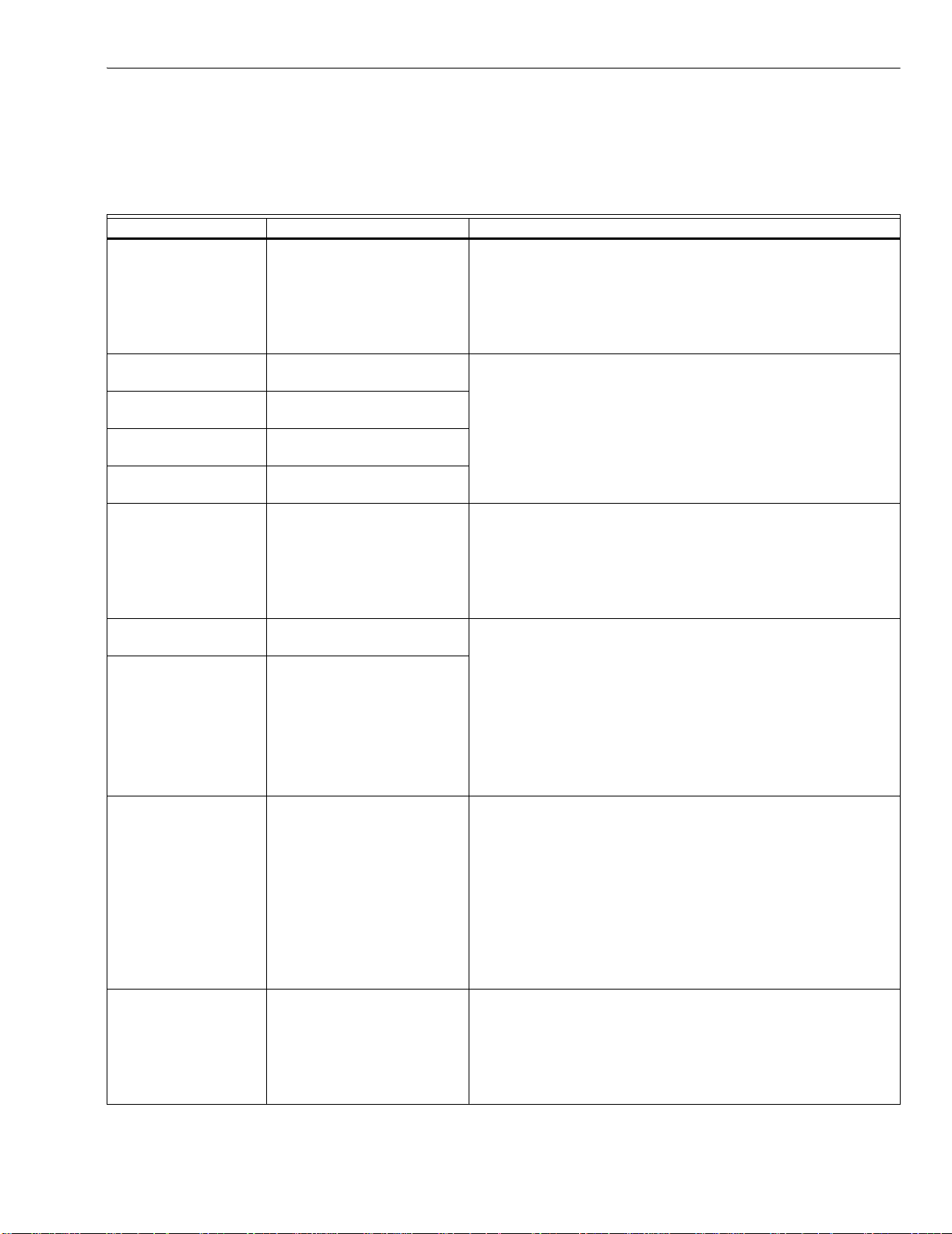
Table 7. Hold and Fault Message Summary.
Fault Code System Failure Recommended Troubleshooting
Fault 1
*No Purge Card*
No card is plugged into the
purge card slot.
1. Make sure the purge card is seated properly.
2. Inspect the purge card and connector on the relay module for
damage or contaminants.
3. Reset and sequence the relay module.
4. If the fault code reappears, replace the purge card.
5. Reset and sequence the relay module.
6. If the fault persists, replace the relay module.
Fault 2
*AC Frequen/Noise
Fault 3
*AC Line Dropout
Fault 4
Excess noise or device running
on slow ac.
Ac line dropout detected.
Device running on fast ac.
1. Check the relay module and display module connections.
2. Reset and sequence the relay module.
3. Check the relay module power supply and make sure that both
frequency and voltage meed the specifications.
4. Check the backup power supply, as appropriate.
*AC Frequency*
Fault 5
Low ac line detected.
*Low Line Voltage*
Fault 6
*Purge Card Error*
Purge card timing changed
since card was initially read.
1. Make sure the purge card is seated properly.
2. Inspect the purge card and connector on the relay module for
damage or contaminants.
3. Reset and sequence the relay module.
4. If the fault code reappears, replace the purge card.
5. Reset and sequence the relay module.
6. If the fault persists, replace the relay module.
Fault 7
*Flame Amplifier*
Fault 8
*Flame Amp/Shutr*
Flame sensed when flame not
present.
Flame sensed when no signal
expected during shutter-check
or Ampli-Check™ versions.
1. Check wiring and correct any errors. Make sure that the flame
sensor wires are in separate conduits. Check for noise
coupling into the flame detector leadwires.
2. Make sure that flame detector and flame amplifier are
compatible.
3. Remove the flame amplifier and inspect connections. Reset
the flame amplifier.
4. Reset and sequence the relay module.
5. If the code reappears, replace the amplifier.
6. If the fault persists, replace the flame detector.
7. If the fault persists, replace the relay module.
Fault 9
*Flame Detected*
Flame sensed when no flame is
expected during STANDBY.
1. Check that flame is not present in the combustion chamber;
correct any errors.
2. Check wiring and correct any errors. Make sure that flame
sensor wires are in separate conduits. Check for noise
coupling into flame detector leadwires.
3. Remove the flame amplifier and inspect its connections. Reset
the amplifier.
4. Reset and sequence the relay module.
5. If the code reappears, replace the amplifier and/or the flame
detector.
6. If the fault persists, replace the flame detector.
7. If the fault persists, replace the relay module.
Fault 10
*Preignition ILK*
Preignition Interlock fault during
STANDBY
1. Check wiring and correct any errors.
2. Check Preignition Interlock switches to assure proper
functioning.
3. Check fuel valve operation.
4. Reset and sequence the relay module; monitor the Preignition
Interlock status.
5. If the code persists, replace the relay module.
15 65-0090—4
Page 16
7800 SERIES S7800A KEYBOARD DISPLAY MODULE
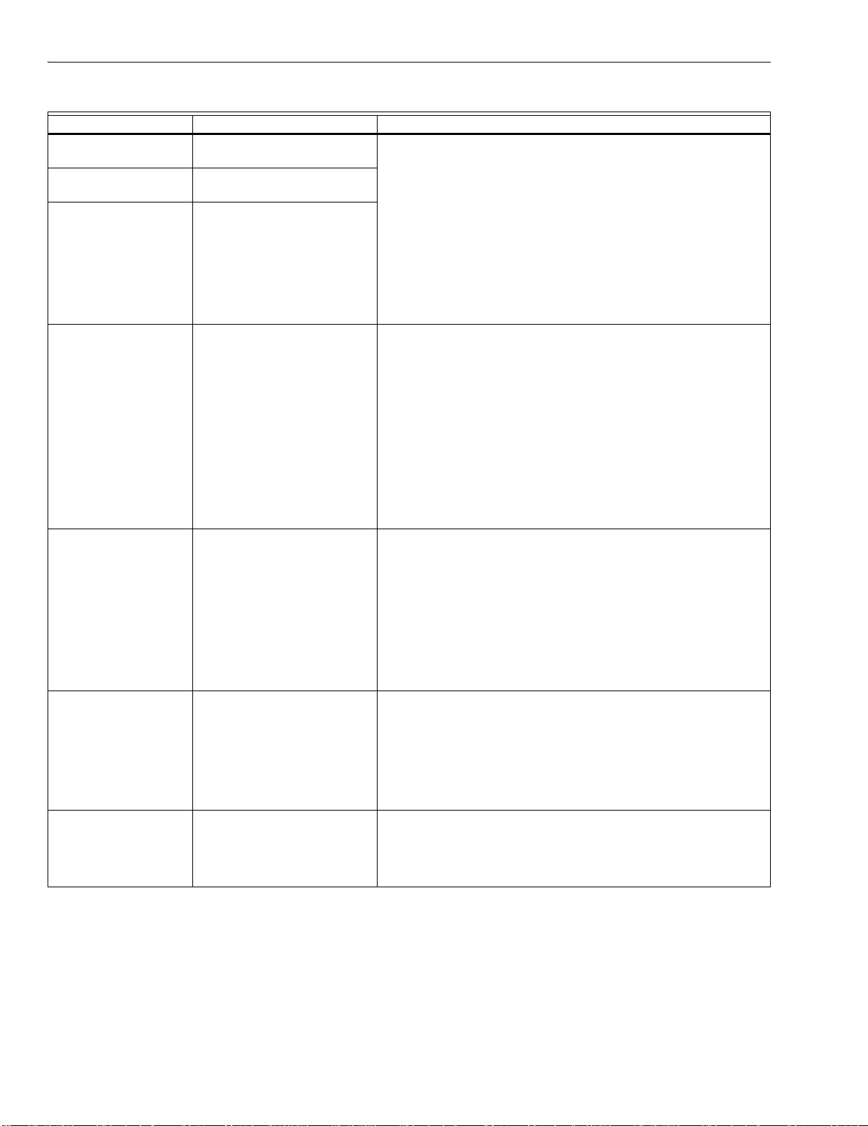
Table 7. Hold and Fault Message Summary (Continued).
Fault Code System Failure Recommended Troubleshooting
Fault 11
*Running ILK On*
Fault 12
*Lockout ILK On*
Fault 13
*Airflow Sw. On*
Running Interlock powered at
improper sequence point.
Lockout Interlock powered at
improper sequence point.
Combustion airflow interlock
fault during STANDBY.
1. Check wiring to make sure that interlocks are connected
properly between terminals 6 and 7. Correct any errors.
2. Reset and sequence the relay module.
3. If the fault persists, measure the voltage between terminals 6
and L2(N) (ground), then terminals 7 and L2(N). If there is line
supply voltage present at terminal 6 when the controller is off,
the controller switch may be bad or jumpered.
4. If steps 1 through 3 are correct and there is line supply voltage
present at terminal 7 when the controller is closed and the fault
persists, check for a welded or jumpered Running Interlock,
Lockout Interlock, or Airflow Switch. Correct any errors.
5. If steps 1 through 4 are correct and the fault persists, replace
the relay module.
Fault 14
*High Fire Sw.*
High Fire Interlock Switch
failure to close during
PREPURGE.
1. Check wiring and correct any errors.
2. Reset and sequence the relay module.
3. Use either the manual motor potentiometer to drive the motor
to the High Fire position or use the Run/Test Switch option, if
available. Sequence to Prepurge drive to High Fire and place
in the Test position. Adjust the High Fire Switch while in this
state to make sure that it closes properly.
4. Measure the voltage between terminal 19 and L2(N) while in
the Prepurge drive to High Fire state. Line supply voltage
should be present. If not, the switch adjustment is incorrect
and/or the switch is defective and needs replacing.
5. Reset and sequence the relay module. If the line supply
voltage was present between the High Fire Switch and terminal
19, and the fault still persists, replace the relay module.
Fault 15
*Flame Detected*
Flame sensed when no flame is
expected during STANDBY.
1. Check that the flame is not present in the combustion
chamber; correct any errors.
2. Make sure that the flame amplifier and flame detector are
compatible.
3. Check wiring and correct any errors.
4. Remove the flame amplifier and inspect the connections.
Reset the flame amplifier.
5. Reset and sequence the relay module.
6. If the code reappears, replace the amplifier and/or the flame
detector.
7. If the fault persists, replace the relay module.
Fault 16
*Flame-Out Timer*
No-flame detected during Pilot
Flame Establishing Period.
1. Measure the flame signal. If one exists, make sure it meets
specifications. Make any necessary burner adjustments using
manufacturer instructions.
2. Make sure that the flame amplifier and flame detector are
compatible.
3. If the code reappears, replace the amplifier and/or the flame
detector.
4. If the fault persists, replace the relay module.
Fault 17
*Main Flame Fail*
Main flame failure during RUN
after flame is established an on
for at least 10 seconds.
1. Inspect the main fuel valve(s) and connection(s).
2. Make sure that the fuel pressure is high enough to supply fuel
to the combustion chamber.
3. Check the flame detector sighting for adequate flame signal
throughout the burner firing rate.
65-0090—4 16
Page 17
7800 SERIES S7800A KEYBOARD DISPLAY MODULE
Table 7. Hold and Fault Message Summary (Continued).
Fault Code System Failure Recommended Troubleshooting
Fault 18
*Flame Detected*
Flame sensed when the shutter
is open and no flame is
expected during PREPURGE.
1. Check that flame is not present in the combustion chamber.
Correct any errors.
2. Make sure that the flame amplifier and flame detector are
compatible.
3. Check the wiring and correct any errors. Make sure F and G
wires are in individual conduits and protected from stray noise
pickup.
4. Remove the flame amplifier and inspect the connectors. Reset
the flame amplifier.
5. Reset and sequence the relay module.
6. If the code reappears, replace the flame amplifier and/or the
flame detector.
7. If the fault persists, replace the relay module.
Fault 19
*Main Flame Ign.*
Flame was lost during MFEP or
the first 10 seconds of the RUN
state.
1. Inspect the main fuel valve(s) and connection(s).
2. Make sure the fuel pressure is high enough to supply fuel to
the combustion chamber.
3. Make sure the flame detector is positioned to obtain the
required flame signal strength; reset and recycle.
Fault 20
*Low Fire Sw. Off*
Low Fire Interlock switch failure
to close during PREPURGE.
1. Check wiring and correct any errors.
2. Reset and sequence the relay module.
3. Use either the manual motor potentiometer to drive the motor
to the Low Fire position or use the Run/Test Switch option, if
available. Sequence to Prepurge drive to Low Fire and place in
the Test Position. Adjust the Low Fire Switch to make sure it
closed properly.
4. Measure the voltage between terminal 18 and L2(N) while in
the Prepurge drive to Low Fire state. Line supply voltage
should be present. If not, the switch adjustment is incorrect
and/or the switch is defective and needs replacing.
5. Reset and sequence the relay module. If line supply voltage
was present between the Low Fire Switch and terminal 18, and
the fault still persists, replace the relay module.
Fault 21
*Running ILK*
Fault 22
*Lockout ILK*
Fault 23
*Airflow Switch*
Running Interlock fault during
PREPURGE.
Lockout Interlock fault during
PREPURGE.
Combustion airflow interlock
fault during PREPURGE.
1. Check wiring and correct any errors.
2. Inspect the fan; make sure there is no blockage of the air
intake and that it is supplying air.
3. Make sure the Interlock Switches are working properly and that
all switch contacts are free of contaminants.
4. Reset and sequence the relay module to PREPURGE (place
the Run/Test Switch in the Test position, if available). Measure
the voltage between terminals 7 and L2(N). Line voltage
should be present.
5. If steps 1 through 4 are correct and the fault persists, replace
the relay module.
Fault 24
*Call Service*
The flame interlock (relay
module) was on when it should
1. Check for F leadwire routing. Make sure routing is in its conduit
and isolated from noise-producing circuits.
be off.
Fault 25
*Call Service*
The flame interlock (relay
module) was off when it should
be on.
Fault 26
*Man-Open Sw. Off*
The Manual Open Valve Switch
was off when it should be on
(Device specific).
1. Check wiring and correct any errors.
2. Make sure that the Manual Open Valve Switch is fully open.
3. Make sure that the Manual Open Valve Switch is functioning
properly and that the switch contacts are free from
contaminants.
4. Reset and sequence the relay module.
5. Make sure that the Manual Open Valve Switch provides an
electrical path when closed. Verify that the relay module is
receiving power at terminal 17.
6. If steps 1 through 5 are correct and the fault persists, replace
the relay module.
17 65-0090—4
Page 18
7800 SERIES S7800A KEYBOARD DISPLAY MODULE
Table 7. Hold and Fault Message Summary (Continued).
Fault Code System Failure Recommended Troubleshooting
Fault 27
*Start Switch On*
Start Switch was on during
PREPURGE (Device specific).
1. Start Switch held on too long.
2. Check wiring; verify that Start Switch is correctly connected.
3. Make sure that the Start Switch is functioning properly and that
the switch contacts are free of contaminants.
4. Reset and sequence the relay module to PREPURGE; set the
Run/Test Switch to Test. Make sure there is no power at
terminal 6 during PREPURGE.
5. If steps 1 through 4 are correct and the fault persists, replace
the relay module.
Fault 28
*Pilot Flame Fail*
Pilot flame failure. 1. Check pilot valve wiring and operation. Correct any errors.
2. Check fuel supply.
3. Check pilot pressure and repeat pilot turndown test.
4. Check ignition transformer electrode, flame detector, flame
detector sighting and flame amplifier.
5. If steps 1 through 4 are correct and the fault persists, replace
the relay module.
Fault 29
*Lockout ILK*
Lockout Interlock fault. 1. Check wiring and correct any errors.
2. Inspect the fan; make sure that there is no blockage of the air
intake and that it is supplying air.
3. Make sure that the Lockout Interlock Switches are working
properly and that all switch contacts are free from
contaminants.
4. Reset and sequence the relay module to PREPURGE (place
the Run/Test Switch in the Test position, if available). Measure
the voltage between terminals 7 and L2(N). Line voltage
should be present.
5. If steps 1 through 4 are correct and the fault persists, replace
the relay module.
Fault 30
*Running ILK*
Running Interlock fault. 1. Inspect the Running Interlocks, including the Airflow Switch,
and the connections.
2. Make sure that the Running Interlocks, including the Airflow
Switch, are functioning properly and that switch contacts are
free from contaminants.
3. Reset and sequence the relay module to PREPURGE. Set the
Run/Test Switch, if available, to Test. Measure the voltage
between terminal 7 and L2(N). Line voltage should be present.
4. If steps 1 through 3 are correct and the fault persists, replace
the relay module.
Fault 31
*Low Fire Sw. Off*
Low Fire Interlock Switch failure
to close during RUN (Device
specific).
1. Check wiring and correct any errors.
2. Reset and sequence the relay module.
3. Use either the manual motor position to drive the motor to the
Low Fire position, or use the Run/Test Switch option, if
available. Sequence to Run drive to Low Fire and place the
switch in the Test position. Adjust the Low Fire Switch while in
this state to make sure it is closing properly.
4. While in Run, drive to Low Fire state, measure the voltage
between terminal 18 and L2(N). Line voltage should be
present. If not, the switch adjustment is incorrect and/or the
switch is defective and needs replacement.
5. Reset and sequence the relay module. If line voltage was
present between the Low Fire Switch and terminal 18, and the
fault persists, replace the relay module.
65-0090—4 18
Page 19
7800 SERIES S7800A KEYBOARD DISPLAY MODULE
Table 7. Hold and Fault Message Summary (Continued).
Fault Code System Failure Recommended Troubleshooting
Fault 32
*Airflow Switch*
Fault 33
*Preignition ILK*
Fault 34
*Control On*
Fault 35
*Call Service*
Fault 36
*Call Service*
Fault 37
*Call Service*
Fault 38
*Call Service*
Fault 39
*Call Service*
Fault 40
*Call Service*
Fault 41
*Main Valve On*
Fault 42
*Pilot Valve On*
Fault 43
*Ignition On*
Fault 44
*Pilot Valve 2 On*
Combustion Airflow Interlock
fault.
Preignition Interlock fault. 1. Check wiring and correct any errors.
CTL input was energized at the
wrong time for the relay
module. This fault implies a
field wiring error.
Safety relay was off when it
should be on or the internal
fuse has blown.
Main valve terminal was off
when it should be on, or the
internal fuse has blown.
Pilot (ignition) valve terminal
was off when it should be on, or
the internal fuse has blown.
Ignition terminal was off when it
should be on, or the internal
fuse has blown.
V2S valve terminal (usually
terminal 21) was off when it
should be on, or the internal
fuse has blown.
Safety relay was on when it
should be off.
Main valve terminal was on
when it should be off.
Pilot (ignition) valve terminal
was on when it should be off.
Ignition terminal was on when it
should be off.
V2S valve terminal, used as a
pilot, is on when it should be off.
1. Check wiring and correct any errors.
2. Inspect the fan; make sure there is no blockage of the air
intake and it is supplying air.
3. Make sure the Airflow Interlock Switches are working properly
and all switch contacts are free from contaminants.
4. Reset and sequence the relay module to PREPURGE. Place
the Run/Test Switch in the Test position, if available. Measure
the voltage between terminals 7 and L2(N). Line voltage
should be present.
5. If steps 1 through 4 are correct and the fault persists, replace
the relay module.
2. Inspect the Preignition Interlock switches and make sure they
function properly.
3. Check fuel valve operation. Valve must close within five
seconds.
4. Reset and sequence the relay module.
5. During STANDBY or PREPURGE, measure the voltage
between terminal 20 and L2(N). Line voltage should be
present. If not, the Preignition Interlock switches can be
defective and need replacing.
6. If the fault persists, replace the relay module.
1. Check wiring and correct any errors.
2. Reset and sequence the relay module.
3. If fault persists, replace the relay module.
1. Reset and sequence the relay module. If fault repeats, replace
relay module, but be sure to test for excessive loads on
appropriate terminals described by fault code.
2. If fault does not repeat on next cycle, check for electrical noise
being coupled into the relay module through the loads on
appropriate terminals described by the fault code.
3. Possibly check for bouncing running on Lockout Interlock.
4. If fault persists, replace the relay module.
WARNING
Explosion Hazard.
Can cause severe injury, death or property damage.
1. Remove system power, turn off fuel supply.
2. Check for wiring errors that could provide power to
terminals described by the fault. Correct any errors.
3. Re-power system; reset and sequence the relay module.
4. If fault persists, replace the relay module.
5. When fault is corrected, turn on fuel supply.
19 65-0090—4
Page 20
7800 SERIES S7800A KEYBOARD DISPLAY MODULE
Table 7. Hold and Fault Message Summary (Continued).
Fault Code System Failure Recommended Troubleshooting
Fault 45
*Low Fire Sw. Off*
Fault 46
*Flame Amp Type*
Fault 47
*Jumpers Changed*
Fault 48
*Delayed MV On*
(2nd Stage Valve)
Fault 49
*Man-Open Sw. On*
Fault 50
*Jumpers Wrong*
Low Fire Interlock switch failure
to close or stay closed.
Device specific. 1. Remove power to the device.
The configuration jumpers differ
from the sample taken at
startup.
V2S valve terminal, used as a
delayed main valve, was on
when it should be off.
The manual open switch was
on when it should be off.
The sequence logic detected a
combination of jumpers that is
illegal for the sequence, e.g., if
it is correct to clip jumper JR1
or Jumper JR2, but not both,
this fault would be used when
both are clipped (Device
specific).
1. 1. Check wiring and correct any errors.
2. 2. Reset and sequence the relay module.
3. 3. Use either the manual motor position to drive the motor to
the Low Fire position, or use the Run/Test Switch option, if
available. Sequence to Run, drive to Low Fire and place in the
Test position. Adjust the Low Fire Switch while in this state to
make sure it is closing properly.
4. 4. While in Run, drive to Low Fire state, measure the voltage
between terminal 18 and L2(N). Line voltage should be
present. If not, the switch adjustment is incorrect and/or the
switch is defective and needs replacement.
5. 5. If steps 1 through 4 are correct and the fault still persists,
replace the relay module.
2. Reset the flame amplifier and reset and sequence the relay
module.
1. Inspect the jumper connections. Make sure that clipped
jumpers are completely removed.
2. Reset and sequence the relay module.
3. If fault persists, replace the relay module.
WARNING
Explosion Hazard.
Can cause severe injury, death or property damage.
1. Remove system power, turn off fuel supply.
2. Check wiring; correct any errors.
3. Inspect the V2S Fuel Valve and its connections. Make sure
the switch is working correctly and is not jumpered or
welded.
4. Reset and sequence the relay module.
5. If fault persists, replace the relay module.
WARNING
Explosion Hazard.
Can cause severe injury, death or property damage.
1. Remove system power, turn off fuel supply.
2. Check wiring; correct any errors.
3. Inspect the Manual-Open Switch and its connections.
Make sure the switch is working correctly and is not
jumpered or welded.
4. Reset and sequence the relay module.
5. If fault persists, replace the relay module.
1. Inspect the jumpers and refer to the installation instructions for
compatible jumper configurations.
2. Make sure that clipped jumpers are completely removed.
3. Reset and sequence the relay module.
4. If fault persists, replace the relay module.
65-0090—4 20
Page 21
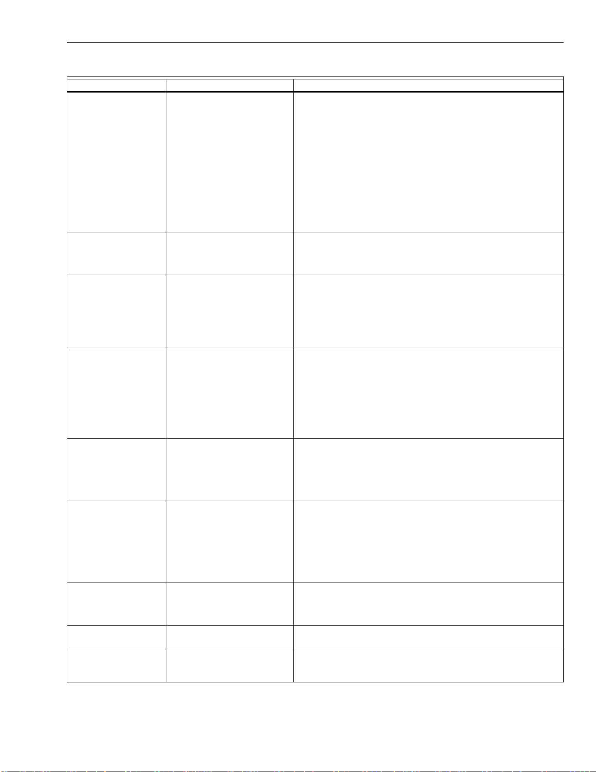
7800 SERIES S7800A KEYBOARD DISPLAY MODULE
Table 7. Hold and Fault Message Summary (Continued).
Fault Code System Failure Recommended Troubleshooting
Fault 51
*Flame Too Strong*
Flame signal value is too high
to be valid.
1. Make sure that flame detector and flame amplifier are
compatible.
2. Remove the flame amplifier and inspect the connections.
Reset the flame amplifier.
3. Reset and sequence the relay module.
4. Check the flame detector sighting position, reset and cycle.
5. Verify that no ignition noise is present in the F lead due to wire
routing.
6. Measure the flame strength. Verify it meets specifications. If
not, refer the flame amplifier and/or flame detector checkout
procedures.
7. If the code reappears, replace the flame amplifier.
8. If the code reappears, replace the flame detector.
9. If the fault persists, replace the relay module.
Fault 52
*Call Service*
Pilot Valve 2 (terminal 21) was
off when it should be on.
1. Inspect terminal 21 and connections. Make sure that the valve
is operating properly.
2. Reset and sequence the relay module.
3. If the fault persists, replace the relay module.
Fault 53
*Lockout Switch*
Lockout Input fault
(EC/RM7850 only).
1. Check wiring and correct any errors.
2. Inspect the Lockout Switch to make sure it is working properly.
3. Reset and sequence the relay module. During STANDBY or
PREPURGE, measure the voltage between terminal 20 and
L2(N). Supply voltage should be present. If not, the lockout
switch is defective and needs replacing.
4. If the fault persists, replace the relay module.
Fault 54
*Comb. Pressure*
Combustion pressure switch
fault (Fulton pulse only).
1. Check wiring and correct any errors.
2. Inspect the Combustion Pressure Switch to make sure it is
working correctly.
3. Reset and sequence the relay module.
4. During STANDBY and PREPURGE, measure the voltage
between terminal 20 and L2(N). Supply voltage should be
present. If not, the Combustion Pressure Switch is defective
and needs replacing.
5. If the fault persists, replace the relay module.
Fault 55
*Purge Fan Sw. On*
Purge fan switch is on when it
should be off (Fulton pulse
only).
1. Check wiring and correct any errors.
2. Inspect the Purge Fan Switch terminal 18 and its connections.
Make sure the switch is working correctly and is not jumpered
or welded.
3. Reset and sequence the relay module.
4. If the fault persists, replace the relay module.
Fault 56
*Block Intake*
Block intake fault (Fulton pulse
only).
1. Check wiring and correct any errors.
2. Inspect the Block Intake Switch and make sure it is working
properly.
3. Reset and sequence the relay module.
4. During PREPURGE, measure the voltage between terminal 7
and L2(N). Supply voltage should be present. If not, the Block
Intake Switch is defective and needs replacing.
5. If the fault persists, replace the relay module.
Fault 57
*Purge Fan Sw. Off*
Purge Fan Switch is off when it
should be on (Fulton pulse
only).
1. Inspect the Prepurge Fan Switch terminal 18 and the
connections. Make sure the fan is working properly.
2. Reset and sequence the relay module.
3. If the fault persists, replace the relay module.
FAult 58 - 66
Unused faults. —
*Call Service*
Fault 67
*AC Phase*
L1 and L2
miswired/exchanged
1. Check L1 and L2 for proper line phasing.
(EC/RM7850 only).
21 65-0090—4
Page 22
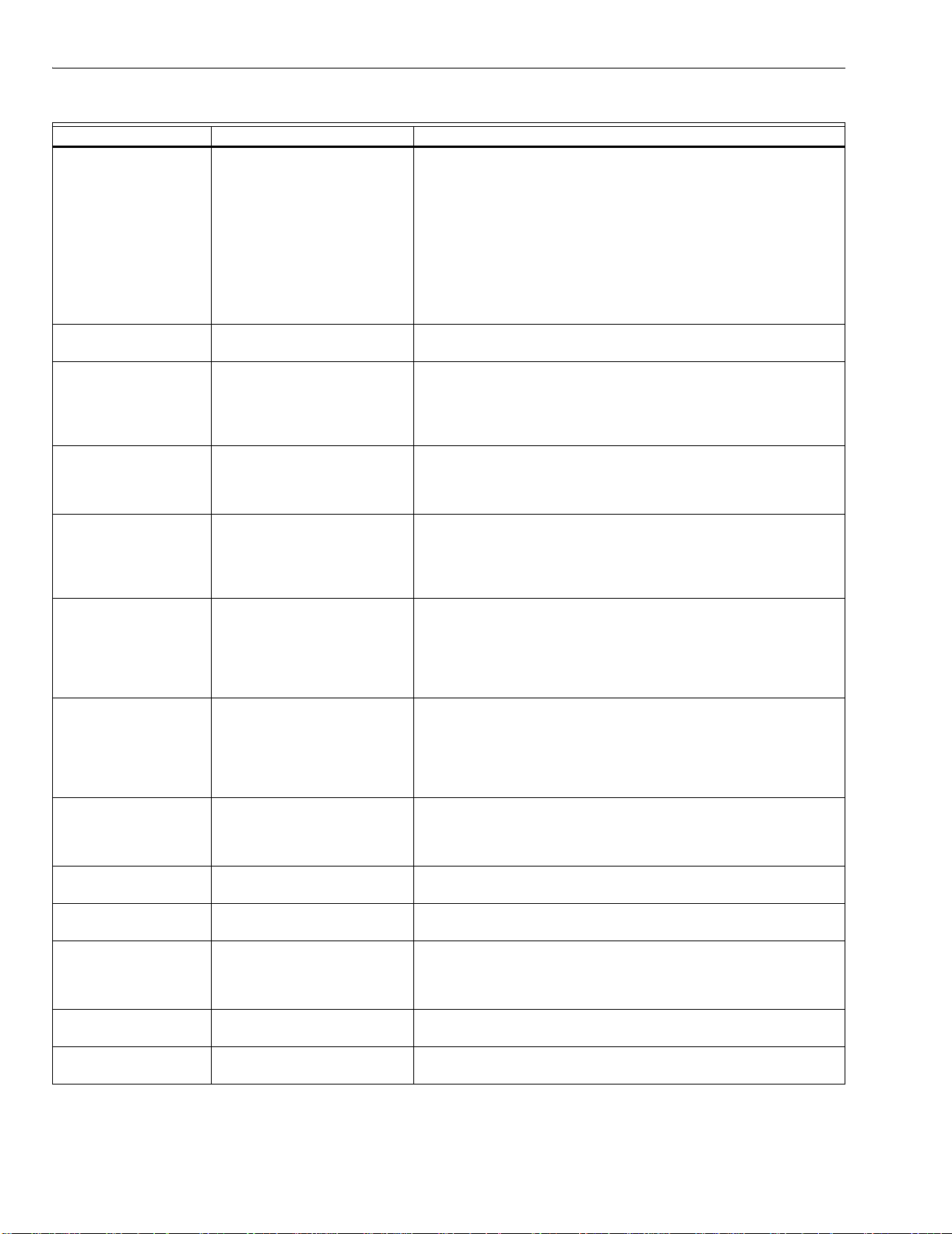
7800 SERIES S7800A KEYBOARD DISPLAY MODULE
Table 7. Hold and Fault Message Summary (Continued).
Fault Code System Failure Recommended Troubleshooting
Fault 68
*Preignition ILK*
Preignition Interlock fault. 1. Check wiring and correct any errors.
2. Inspect the Preignition Interlock switches and make sure they
work properly.
3. Check fuel valve operation. Valve must close within five
seconds.
4. Reset and sequence the relay module.
5. During STANDBY or PREPURGE, measure the voltage
between terminal 17 and L2(N). Supply voltage should be
present. If not, the Preignition Interlock switches are defective
and need replacing.
6. If the fault persists, replace the relay module.
Faults 69 - 70
Unused faults. —
*Call Service*
Fault 71
*Dynamic LFS*
Low Fire Switch closed, High
Fire Switch must be open
(EC/RM 7850 only).
1. Check firing rate position switches (usually in Modutrol®
Motor) for proper operation.
2. Check wiring and correct any errors.
3. Reset and sequence the relay module.
4. If the fault persists, replace the relay module.
Fault 71
*Limits Complete*
Limit Input (terminal 7) is off
when it should be on (RM7888
only).
1. Check limits to make sure they are satisfied after resetting.
2. Check electrical connections to terminal 7 of wiring subbase.
3. Reset relay module.
4. If the fault persists, replace the relay module.
Fault 72
*Dynamic HFS*
High Fire Switch closed; Low
Fire Switch must be open
(EC/RM7850 only).
1. Check firing rate position switches (usually in Modutrol®
Motor) for proper operation.
2. Check wiring and correct any errors.
3. Reset and sequence the relay module.
4. If the fault persists, replace the relay module.
Fault 72
*Spec.Func.2*
Special Function 2 Input
(terminal 17) is off when it
should be on (Device specific).
1. Check operation of Special Function 2 of PLC.
2. Check electrical connection to terminal 17 of wiring subbase
and confirm presence of supply power when Special Function
2 is activated.
3. Reset relay module.
4. If the fault persists, replace the relay module.
Fault 73
*Spec.Func.3*
Special Function 3 Input
(terminal 19) is off when it
should be on (Device specific).
1. Check operation of Special Function 3 of PLC.
2. Check electrical connection to terminal 19 of wiring subbase
and confirm presence of supply power when Special Function
2 is activated.
3. Reset relay module.
4. If the fault persists, replace the relay module.
Fault 75
*Flame Proven
Feedback*
Flame Indication Feedback
(terminal 21) either on when it
should be off or off when it
1. Remove wire to terminal 21 and reset relay module.
2. If the fault persists, replace relay module.
3. Reconnect wire to terminal 21. If the fault returns, verify wiring.
should be on (Device specific).
Faults 76 - 93
——
*Accessory Fault*
Faults 94 - 104
——
*Call Service*
Fault 105
*Call Service*
Relay Module self-test failure. 1. Reset and sequence the relay module.
2. If the fault reappears, remove power from the relay module and
reapply the power; reset and sequence the relay module.
3. If the fault persists, replace the relay module.
Fault 106
Relay Module self-test failure.
*Call Service*
Fault 107
*Call Service*
Relay Module flame signal
crosscheck failure.
—
65-0090—4 22
Page 23
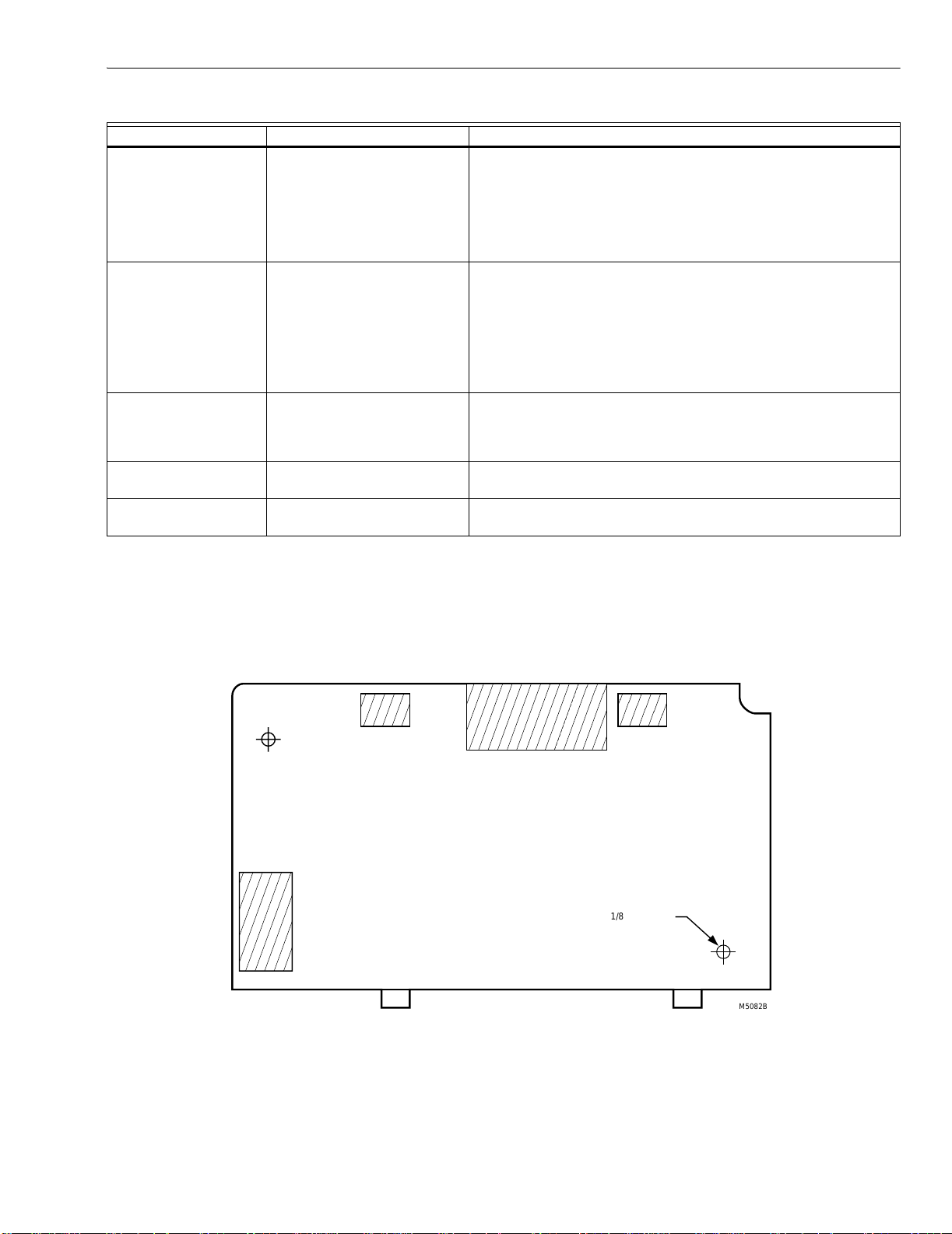
7800 SERIES S7800A KEYBOARD DISPLAY MODULE
Table 7. Hold and Fault Message Summary (Continued).
Fault Code System Failure Recommended Troubleshooting
Fault 109
*Call Service*
Negative cycle test failed, earth
ground absent or line voltage
phasing improper.
1. Make sure a good earth ground connection exists at the
installation site and all earth ground connections are complete
and correct.
2. Make sure the relay module and all loads operate at the same
line voltage phase.
3. Reset and sequence the relay module.
4. If the fault persists, replace the relay module.
Fault 110
*Call Service*
The configuration jumpers differ
from stored values.
1. Inspect the jumper connections. Make sure they match the
original selection and clipped jumpers are completely removed.
2. Reset and sequence the relay module.
3. If the fault persists, replace the relay module.
4. Configuration jumpers must be selected prior to 200 hours of
operation. If configuration jumpers are changed after 200
hours of operation, lockout 110 occurs. Relay module cannot
be reset and must be replaced.
Fault 111
*Call Service*
Relay Module configuration
jumper test failure.
1. Inspect the jumper connections. Make sure they match the
original selection and clipped jumpers are completely removed.
2. Reset and sequence the relay module.
3. If the fault persists, replace the relay module.
Fault 112 - 126
*Call Service*
Fault 127
*Call Service*
Relay Module self-test failure. 1. Reset and sequence the relay module.
2. If the fault persists, replace the relay module.
Safety relay feedback circuit
was in an improper state.
1. Reset and sequence the relay module.
2. If the fault persists, replace the relay module.
Expanded Annunciator Messages
If an Expanded Annunciator is wired to the limit control and
interlock control strings, and connected to the 7800 SERIES
Relay Module, additional hold messages, fault messages or
code numbers enhance the original hold messages, fault
messages or code numbers. See the Expanded Annunciator
specification, form 65-0101, for detailed information. The
message demonstrates which device opened first in a
monitored string of limits or interlocks.
1/8 in. DIA. (2)
(3.175 mm)
M5082B
Fig. 16. KDM flush mounting outline.
23 65-0090—4
Page 24

7800 SERIES S7800A KEYBOARD DISPLAY MODULE
®
™
Contact Esys for more information about this product:
Esys® The Energy Control Company™ website: http://www.esys.us
4520 Stine Road, Ste 7
Bakersfield, CA 93313
(661) 833-1902
email: esys.us
Automation and Control Solutions Honeywell International Honeywell Europe S.A. Honeywell Latin American
Honeywell Honeywell Limited-Honeywell Limitée Control Products 3 Avenue du Bourget
1985 Douglas Drive North 35 Dynamic Drive Honeywell Building 1140 Brussels 480 Sawgrass Corporate Parkway
Golden Valley, MN 55422 Scarborough, Ontario 17 Changi Business Park Central 1 Belgium Suite 200
M1V 4Z9 Singapore 486073 Sunrise FL 33325
Region
65-0090—4 G.R. Rev. 07-02 www.honeywell.com
Printed in U.S.A. on recycled
paper containing at least 10%
post-consumer paper fibers.
 Loading...