

APPLICATION
The Q7100 Thermostat Subbases provide electronic
control of commercial 24 Vac single or multistage heat
pump or conventional heating and cooling systems.
Select models have terminals for light emitting diodes
LEDs, remote temperature sensors and remote setback
timer. The LED models have up to two field configurable
LEDs and up to two factory assigned LEDs. Refer to
Table 1. All Q7100 Thermostat Subbases require a
common wire to the supply power.
Table 1. Description of Q7100 Subbases.
a
Use
T7100
Q7100
AD or F Conventional 1 or 2 1 or 2 8-9
CE or F Heat pump 1, 2 or 3 1 or 2 10-14
DE or F Heat pump 1 or 2 1 or 2 15
a
Depends on the model.
System Heat Cool Figs.
Stages
Q7100A,C,D
Thermostat Subbases
INSTALLATION INSTRUCTIONS
3. Installer must be a trained, experienced service
technician.
4. After completing installation, use these instructions
to check out the product operation.
CAUTION
Disconnect power supply to prevent electrical
shock or equipment damage.
Location
Subbase without Remote-Mounted Temperature Sensor
Install the subbase about 5 ft (1.5m) above the floor in an
area with good air circulation at average temperature.
See Fig. 1.
Do not install the subbase where it can be affected by:
— drafts, or dead spots behind doors and in corners.
— hot or cold air from ducts.
— radiant heat from sun or appliances.
— concealed pipes and chimneys.
— unheated (uncooled) areas such as an outside wall
behind the thermostat.
RECYCLING NOTICE
If this control is replacing a control that contains
mercury in a sealed tube, do
control in the trash.
Contact your local waste management authority
for instructions regarding recycling and the proper
disposal of the old thermostat.
INSTALLATION
When Installing this Product...
1. Read these instructions carefully. Failure to follow
the instructions can damage the product or cause
a hazardous condition.
2. Check the ratings given in the instructions and on
the product to make sure the product is suitable for
your application.
®U.S. Registered Trademark
Copyright © 1996 Honeywell Inc. • • All Rights Reserved
not
place your old
Subbase with Remote-Mounted Temperature Sensor(s)
Install the subbase in an area that is accessible for
setting and adjusting the temperature and settings.
Install the remote-mounted sensor(s) about 5 ft (1.5m)
above the floor in an area with good air circulation at
average temperature. See Fig. 1.
Do not mount the sensor(s) where it can be affected by:
— drafts, or dead spots behind doors and in corners.
— hot or cold air from ducts.
— radiant heat from sun or appliances.
— concealed pipes and chimneys.
— unheated (uncooled) areas such as an outside wall
behind the thermostat.
If more than one remote sensor is required, they must be
arranged in a temperature averaging network consisting
of two, three, four, five or nine sensors. See Fig. 2
through 6.
X-XX UL
69-0931-3
Q7100A,C,D THERMOSTAT SUBBASES
NO
NO
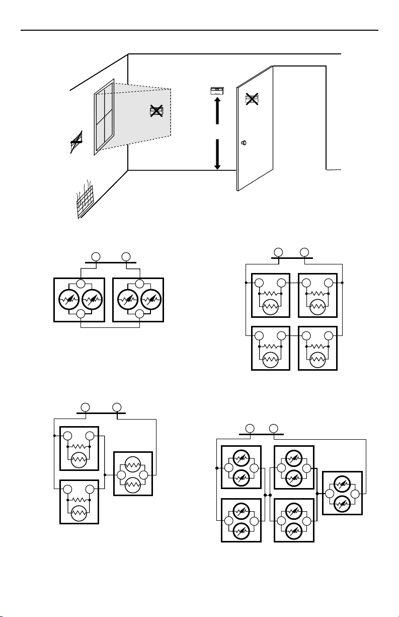
Fig. 1. Typical location of thermostat or remote-mounted sensor.
SUBBASE
TT
T7047GT7047G
T
T
Fig. 2. Two T7047G Sensors providing a
temperature averaging network for a
T7100/Q7100 Thermostat/Subbase.
SUBBASE
TT
T7047C
TT
T
T
M4838
T7047G
YES
5 FEET
[1.5 METERS]
NO
SUBBASE
TT
T7047C
TT
T7047C
TT
Fig. 4. Four T7047C Sensors providing a
temperature averaging network for a
T7100/Q7100 Thermostat Subbase.
SUBBASE
TT
T7047G
T7047G
M10074
T7047C
TT
T7047C
TT
M4840
T7047C
TT
Fig. 3. Two T7047C Sensors and one T7047G Sensor
providing a temperature averaging network
for a T7100/Q7100 Thermostat/Subbase.
TT
M4839
69-0931—3
T
T7047G
T
Fig. 5. Five T7047G Sensors providing a
temperature averaging network for a
T7100/Q7100 Thermostat/Subbase.
T
T
T7047G
T
T
2
T
T7047G
T
T
T
M4841
 Loading...