

Honeywell Q674A-G, Q674A-E User Manual

TRADELINE
Thermostats/Q674A-E,G Subbases
®
T874A-F Multistage
Installation Instructions for the Trained Service Technician.
Application
The T874A-F Thermostats provide 24 to 30 Vac control
for heating and/or cooling systems as listed in Table 1.
TABLE 1—THERMOSTAT HEATING AND/OR
T874 A B C D E F
Heating Stages 1 122—2
Cooling Stages 1 2122—
The Q674A-E,G Subbases provide wiring terminals,
system and fan switching, and mounting bases for T874
Thermostats as listed in Table 2.
TABLE 2—SUBBASE SWITCHING POSITIONS.
Q674 Switch Positions
Model System Fan
A Heat-Auto-Cool Auto-On
B Heat-Off-Cool Auto-On
C Off-Auto Auto-On
D None None
E Off-Heat-Auto-Cool Auto-On
G Off-Auto None
COOLING STAGES.
Operation
On a 2-heat thermostat, the two stages of heat make
sequentially as the temperature drops. Make refers to the
mercury switch initiating a call for heat or cool.
There are about 2° F [1° C] between stages so that the
second stage makes only when the first stage cannot handle
the load. This is the interstage differential.
Recycling Notice
M3375
This control contains mercury in a sealed tube. Do not
place control in the trash at the end of its useful life.
If this control is replacing a control that contains mercury in a sealed tube, do not place your old control in the
trash.
Contact your local waste management authority for
instructions regarding recycling and the proper disposal of
this control, or of an old control containing mercury in a
sealed tube.
Installation
WHEN INSTALLING THIS PRODUCT…
1. Read these instructions carefully. Failure to follow
them could damage the product or cause a hazardous condition.
2. Check the ratings given in the instructions and on the
product to make sure the product is suitable for your
application.
3. Installer must be a trained, experienced service technician.
4. After installation is complete, check out product
operation as provided in these instructions.
CAUTION
1. Disconnect power supply to prevent electrical
shock or equipment damage.
2. To prevent interference with the thermostat
linkage, keep wire length to a minimum and
run wires close as possible to the subbase.
3. Do not overtighten thermostat captive mounting screws because damage to subbase threads
can result.
4. Do not short across coil terminals on heating
relay or gas control. This can burn out the
thermostat heat anticipator.
IMPORTANT: Thermostats are calibrated at the factory
by using subbases mounted at true level. Inaccurate
subbase leveling will cause thermostat control deviation.
LOCATION
Locate the subbase about 5 ft [1.5m] above the floor in
an area with good air circulation at average temperature.
Do not mount the subbase where the thermostat may be
affected by:
— drafts or dead spots behind doors and in corners.
— hot or cold air from ducts.
— radiant heat from sun, appliances or fireplace.
— concealed pipes and chimneys.
— unheated (uncooled) areas such as an outside wall
behind the thermostat.
MOUNTING THE SUBBASE
The thermostat subbase can be mounted on a vertical
outlet box, horizontal outlet box or directly on the wall.
1. If you must mount the subbase on a vertical outlet
box, order Honeywell 193121A Adapter Assembly (Fig. 1).
The assembly includes an adapter ring, two screws and a
cover plate to cover marks on the wall. Install the ring and
cover plate on the vertical outlet box.
J.H. • Rev. 5-94 • • ©Honeywell Inc. 1994 • Form Number 60-1165—6
1 60-1165—6
M3375
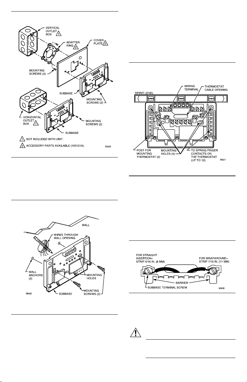
Fig. 1—Installation of subbase on outlet box.
For a wall installation, hold subbase in position and
mark holes for anchors. See Fig. 2. Obtain wall anchors
locally. Take care that the wires do not fall back into the
wall opening. Set aside subbase. Drill two 3/16 in.
[4.8 mm] holes and gently tap anchors into the holes
until flush with the wall.
Fig. 2—Installation of subbase on wall.
3. Secure the cover plate (if used) and subbase with the
screws provided. Do not fully tighten the subbase screws.
4. Level the subbase using a spirit level, as shown in
Fig. 3, and firmly tighten subbase mounting screws. The
subbase mounting holes provide for minor out-of-level
adjustments.
IMPORTANT: An incorrectly leveled subbase will cause
the temperature control to deviate from setpoint.
Fig. 3—Subbase components and leveling
procedure.
WIRING THE SUBBASE
All wiring must comply with local electrical codes and
ordinances. Follow equipment manufacturer wiring instructions when available. To wire subbase, proceed as
follows:
1. Connect the system wires to the subbase as shown in
Figs. 8 through 16. A letter code is located near each
terminal for identification. The terminal barrier permits
straight or conventional wraparound wiring connections.
See Fig. 4.
2. Pull electrical wires through the cover plate (if
used) and subbase cable opening (Fig. 3). See Wiring the
Subbase section before pulling any wires.
IMPORTANT: Use 18 gauge, color-coded thermostat
cable for proper wiring.
60-1165—6
Fig. 4—Wiring connections.
2. Your Q674 Subbase can require one or more jumpers
that may or may not be factory supplied. Refer to the wiring
diagrams for specific terminals to be jumpered. See Table 3
for proper application.
CAUTION
Never install more than one wire per terminal
unless factory supplied jumper with spade terminal is used. See Fig. 7.
2

TABLE 3—JUMPER APPLICATIONS.
If your subbase has: Application Use Fig.
RC, RH terminals single transformer 5
system
adjacent terminals special system 6
operation or LED
nonadjacent indication 7
terminals
3. Firmly tighten each terminal screw.
4. Fit wires as close as possible to the subbase. Push
excess wire back into the hole.
5. Plug hole with nonflammable insulation to prevent
drafts from affecting the thermostat.
Fig. 5—Jumper RC and RH for single transformer system. Strip wire 3/4 in. [19 mm].
Fig. 6—Jumper adjacent terminals for special
system hookup. Strip wire 3/4 in. [19 mm].
Fig. 7—For nonadjacent terminals, use jumper
supplied with subbase.
NOTE: Only the T874D Thermostat is shown with the
subbases. This thermostat/subbase provides 2-stage heating and 2-stage cooling connections. If using another
model, see Fig. 16 and Table 4.
TABLE 4—THERMOSTAT BULB
CONFIGURATOIN.
Model No. Heating Bulbs Cooling Bulbs
T874A H1 C1
T874B H1 C1,C2
T874C H1, H2 C1
T874D H1, H2 C1, C2
T874E C1, C2
T874F H1, H2
3 60-1165—6
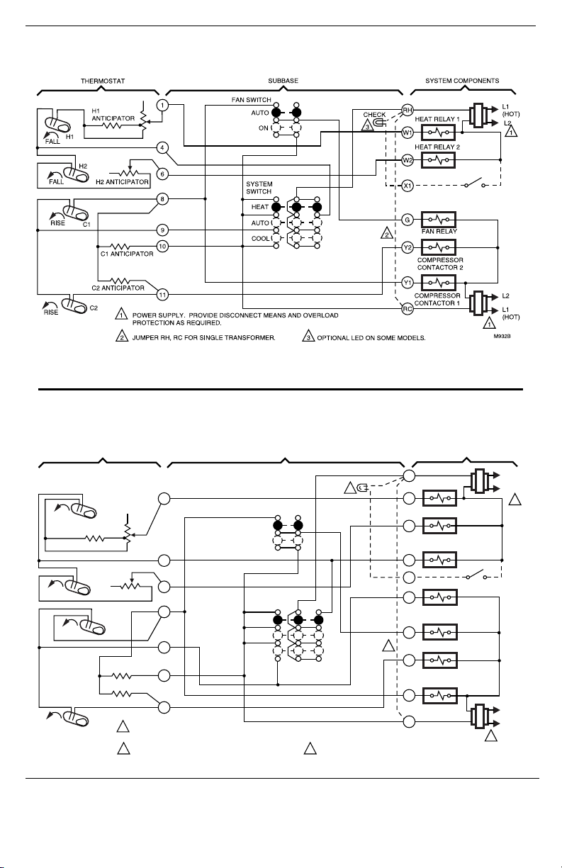
Fig. 8—T874A-D/Q674A in standard heating/cooling system.
Fig. 9—T874C,D/Q674B in standard heating/cooling system with separate transformers for heating and
cooling.
FALL
H1 ANTICIPATOR
FALL
RISE
RISE
60-1165—6
THERMOSTAT
H1
H2
H2 ANTICIPATOR
C1
C1 ANTICIPATOR
C2 ANTICIPATOR
C2
SUBBASE SYSTEM COMPONENTS
1
4
6
8
9
10
11
1
POWER SUPPLY. PROVIDE DISCONNECT MEANS AND OVERLOAD
PROTECTION AS REQUIRED.
2
JUMPER RH, RC FOR SINGLE TRANSFORMER.
FAN
SWITCH
AUTO
ON
SYSTEM
SWITCH
HEAT
OFF
COOL
4
3
2
3
OPTIONAL LED ON SOME MODELS.
RH
HEAT RELAY 1
W1
HEAT RELAY 2
W2
HEAT CHANGEOVER
VALVE
B
X1
O
COOL CHANGEOVER
VALVE
G
FAN RELAY
Y2
COMPRESSOR
CONTACTOR 2
Y1
COMPRESSOR
CONTACTOR 1
RC
L1
(HOT)
L2
1
L2
L1
(HOT)
1
M933C
 Loading...