

Honeywell Y594, T874, Q674 Installation, Instruction And Service Manual
TRADELINE
®
Y594 Combination Pack
(T874 Multistage Thermostat
and Q674 Subbase)
Installation Instructions for the Trained Service Technician.
Application
The Y594 Pack provides 24 to 30 Vac control of standard
2 stage heating and 1 stage cooling systems.
Operation
The stages of heat make sequentially as the temperature
drops. Make refers to the mercury switch initiating a call
for heat or cool.
There are about 2°F (1°C) between stages so that the
second stage makes only when the first stage cannot handle
the load. This is the interstage differential.
Recycling Notice
M3375
This control contains mercury in a sealed tube. Do not
place control in the trash at the end of its useful life.
If this control is replacing a control that contains mercury
in a sealed tube, do not place your old control in the trash.
Contact your local waste management authority for instructions regarding recycling and the proper disposal of this
control, or of an old control containing mercury in a sealed
tube.
Installation
WHEN INSTALLING THIS PRODUCT…
1. Read these instructions carefully. Failure to follow
them could cause a hazardous condition.
2. Check the ratings given in the instructions and on
the product to make sure the product is suitable for your
application.
3. Installer must be a trained experienced service
technician.
4. After installation is complete, check out product operation as provided in these instructions.
IMPORTANT: An incorrectly leveled subbase will cause
the temperature control to deviate from setpoint. It is
not a calibration problem.
CAUTION
1. Disconnect power supply to prevent electrical
shock or equipment damage.
2. To prevent interference with the thermostat
linkage, keep wire length to a minimum and
run wires as close as possible to the subbase.
3. Do not overtighten thermostat captive mounting screws because damage to subbase threads
can result.
4. Do not short across coil terminals on relay. This
can burn out the thermostat heat anticipator.
LOCATION
Install the thermostat about 5 ft (1.5m) above the floor in
an area with good air circulation at average temperature.
Do not install the thermostat where it may be affected by:
— drafts, or dead spots behind doors and in corners.
— hot or cold air from ducts.
— radiant heat from sun or appliances.
— concealed pipes and chimneys.
— unheated (uncooled) areas such as an outside wall
behind the thermostat.
MOUNT SUBBASE
The thermostat subbase can be mounted on a vertical
outlet box, horizontal outlet box or directly on the wall.
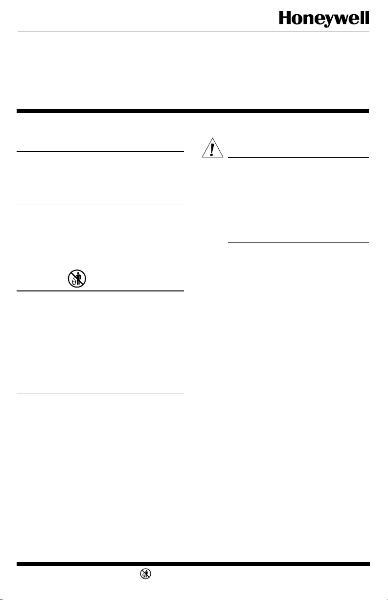
1. If you must mount the subbase on a vertical outlet
box, order Honeywell part no. 193121A Adapter Assembly.
See Fig. 1. The assembly includes an adapter ring, two
screws and a cover plate to cover marks on the wall. Install
the ring and cover plate on the vertical outlet box.
For a wall installation, hold subbase in position and mark
holes for anchors. See Fig. 2. Wall anchors must be obtained
from local hardware store. Be careful that the wires do not
fall back into the wall opening. Set aside subbase. Drill four
3/16 in. (4.6 mm) holes and gently tap anchors into the holes
until flush with the wall.
2. Pull electrical wires through the cover plate (if used)
and subbase cable opening. See Fig. 3.
3. Secure the cover plate (if used) and subbase with the
screws provided. Do not fully tighten the subbase screws.
4. Level the subbase using a spirit level. See Fig. 3, and
firmly tighten subbase mounting screws. The subbase mounting holes provide for minor out-of-level adjustments.
IMPORTANT: An incorrectly leveled subbase will cause
the temperature control to deviate from setpoint. It is
not a calibration problem.
J.H. • 1-95 • • ©Honeywell Inc. 1995 • Printed in U.S.A. • Form Number 69-0882B
M3375
1 69-0882B
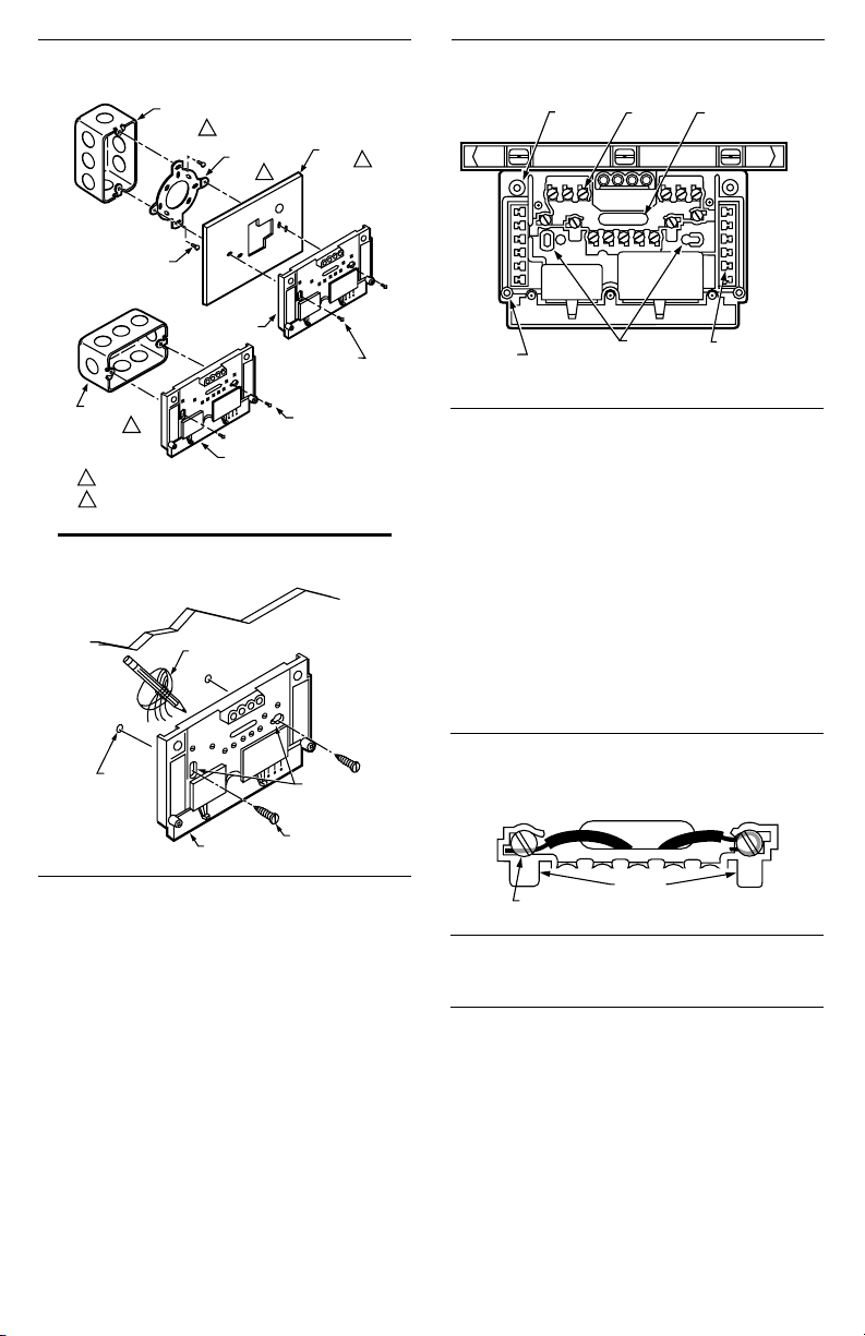
SPIRIT LEVEL
MOUNTING
HOLES (2)
M927
TOP
MOUNTING
HOLES (2)
WIRING
TERMINAL
THERMOSTAT
CABLE OPENING
TO SPRING FINGER
CONTACTS ON THE
THERMOSTAT
(UP TO 12)
POST (2) FOR
MOUNTING
THERMOSTAT
Fig. 1—Installation of Q674 Subbase on outlet
box.
VERTICAL
OUTLET
1
MOUNTING
SCREWS (2)
BOX
ADAPTER
RING
COVER
PLATE
2
Fig. 3—Subbase components and leveling
procedure.
2
SUBBASE
HORIZONTAL
OUTLET
1
BOX
NOT INCLUDED WITH UNIT.
1
ACCESSORY PARTS AVAILABLE (193121A).
2
SUBBASE
MOUNTING
SCREWS (2)
MOUNTING
SCREWS (2)
Fig. 2—Installation of Q674 Subbase on wall.
WALL
WIRES THROUGH
WALL OPENING
WALL
ANCHORS
(2)
M926
SUBBASE
MOUNTING
HOLES
MOUNTING
SCREWS (2)
WIRING THE SUBBASE
All wiring must comply with local electrical codes and
ordinances. Follow equipment manufacturer’s wiring instructions when available. To wire subbase, proceed as follows:
1. Connect the system wires to the subbase. See Figs. 5
and 6. A letter code is located near each terminal for identification. The terminal barrier permits straight or conventional wraparound wiring connection. See Fig. 4.
2. Firmly tighten each terminal screw.
3. Fit wires as close as possible to the subbase. Push
excess wire back into the hole.
4. Plug hole with nonflammable insulation to prevent
drafts from affecting the thermostat.
MOUNT THERMOSTAT
1. Remove the thermostat cover by pulling the bottom
edge of the cover upward until it snaps free of the mounting
slots.
M925
NOTE: The cover is hinged at the top and must be removed
by pulling up at the bottom.
2. Carefully remove and discard the polystyrene packing
insert that protects the mercury switches during shipment.
3. Turn over thermostat base and note the spring fingers
that engage the subbase contacts. Make sure the spring
fingers are not bent flat, preventing proper electrical contact
with the subbase.
4. Note the two tabs on the top inside edge of the
thermostat base. The tabs fit into corresponding slots on top
of the subbase. Mount the thermostat on the subbase.
5. Align the two captive mounting screws in the thermostat base with the posts on the subbase. See Fig. 7. Tighten
both screws. Do not overtighten screws or damage to subbase posts can result.
Fig. 4—Barrier configuration.
FOR STRAIGHT
INSERTION–
STRIP 5/16 in. (8 mm)
SUBBASE TERMINAL SCREW
BARRIER
FOR WRAPAROUND–
STRIP 7/16 in. (11 mm)
M928
Settings
TEMPERATURE SETTING
Move the heating and cooling setpoint levers to the
desired comfort positions. See Fig. 8. One lever control all
stages of heating, and the other lever controls all stages of
cooling. The minimum differential between the heating and
the cooling setpoint is 3°F (1.7°C), which means the setting
levers are made so they cannot be set closer together than
3°F (1.7°C).
69-0882B 2
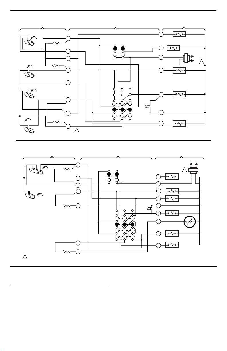
Fig. 5—Schematic and hookup for Y594G.
RISE
FALL
FALL
RISE
H1
H2
CO
C1
H1 ANTICIPATOR
H2 ANTICIPATOR
C1 ANTICIPATOR
2
3
4
5
6
8
9
10
1
POWER SUPPLY. PROVIDE DISCONNECT MEANS AND OVERLOAD PROTECTION AS REQUIRED.
AUTO
ON
EM. HT.
AUTO
OFF
Fig. 6—Schematic and hookup for Y594R.
THERMOSTAT
2
FALL
H1
FALL
H2
POWER SUPPLY. PROVIDE DISCONNECT MEANS AND OVERLOAD PROTECTION AS REQUIRED.
1
H1 & C1
ANTICIPATOR
C1
H2
ANTICIPATOR
RESET HEATER
FAN SWITCH
3
4
5
6
11
12
AUTO
ON
SYSTEM
SWITCH
EM. HT.
HEAT
OFF
COOL
FAN
SWITCH
SUBBASE
SYSTEM
SWITCH
EM. HT.
LED (RED)
SYSTEM COMPONENTSSUBBASETHERMOSTAT
O
COOL CHANGEOVER VALVE
G
FAN RELAY
R
W
AUX. HEAT RELAY
X
EM. HEAT
LED (RED)
EM. HEAT RELAY
B
COMPRESSOR
CONTACTOR
Y
SYSTEM COMPONENTS
FAN RELAY
G
R
AUX. HT. RELAY
W
H
"H" RELAY
B
X
EM. HT. RELAY
T
O
CHANGEOVER VALVE (COOL)
Y
COMPRESSOR
CONTACTOR
L1
(HOT)
1
C815A1039
THERMISTOR
M3173A
L1
(HOT)
L2
L2
1
M5723
Checkout
HEATING
Move the heating setpoint lever on the T874 about
10°F (6°C) above room temperature. Heating equipment
should start and the fan should run. Move the heat lever
about 10°F (6°C) below room temperature. The heating
equipment and fan should shut off.
NOTE: In heat pump applications, a minimum off-timer
provides a five-minute time delay before starting compressor when the thermostat last turned the compressor
off, or when the system first received power. This delay
prevents compressor short cycling.
3 69-0882B
 Loading...