

Page 1
Honeywell
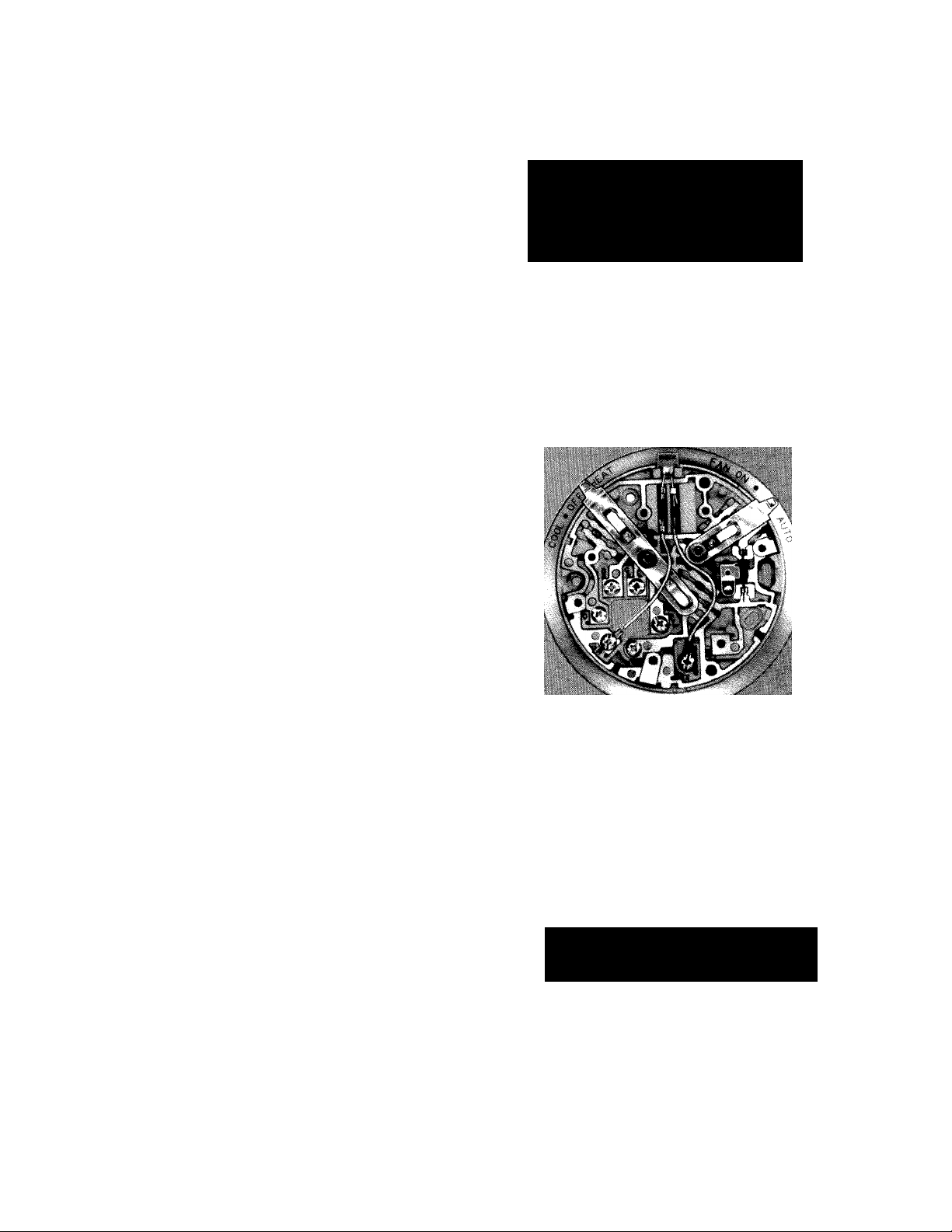
THE Q539 SUBBASES PROVIDE COOLING ANTICI
PATORS. WIRING TERMINALS. AND MOUNTING
BASES FOR T87F THERMOSTATS. MOST ALSO
PROVIDE SYSTEM AND FAN SWITCHING FOR
HEATING. COOLING. AND HEATING-COOLING
THERMOSTATS.
□ Screw terminals for electrical connections are lettercoded for quick, accurate installation.
□ Shunt type carbon heater provides cooling anticipa
tion for close temperature control.
THERMOSTAT
SUBBASES
□ Guide posts assure mounting and leveling necessary
to maintain thermostat calibration.
□ Fan and system switch levers (available on most
models) located at top edge for convenient control.
□ Indicator LED available on most models.
□ Mount directly on wall or on standard outlet box with
accessory wallplate. i
□ Q539P with indicator LED for oil primary systems
(HEAT-only).
Q539A,B,C,F,
D.T.
Rev. 10-89
Form Number 60-2246—4
© Honeywell Inc. 1989
Page 2

SPECIFICATIONS
IMPORTANT
THE SPECIFICATIONS GIVEN IN THIS PUBLICATION DO NOT INCLUDE NORMAL MANUFACTURING TOL
ERANCES. THEREFORE, THIS UNIT MAY NOT MATCH THE LISTED SPECIFICATIONS EXACTLY. ALSO,
THIS PRODUCT IS TESTED AND CALIBRATED UNDER CLOSELY CONTROLLED CONDITIONS, AND SOME
MINOR DIFFERENCES IN PERFORMANCE CAN BE EXPECTED IF THOSE CONDITIONS ARE CHANGED.
TRADELINE MODELS
TRADELINE models are selected and packaged to provide ease of stocking, ease of handling, and maximum
replacement value. Specifications of TRADELINE models are the same as those of standard models except as noted
below.
Q539A,J Thermostat Subbases—provide COOL-OFF-
HEAT system and AUTO-ON fan switching.
0539C Thermostat Subbase—provides COOL-OFF
system and AUTO-ON fan switching.
0539P Thermostat Subbases—provide HEAT-only
and indicator LED for oil primary systems.
FEATURES:
• TRADELINE package with cross reference label
and special instruction sheet.
• Textured beige finish designer models (available
on some TRADELINE models).
STANDARD MODELS
Refer to Table 1 for the general specif ications for 0539
Thermostat Subbases.
ELECTRICAL RATINGS:
Subbase Switches:
Resistive: 2A at 30 Vac maximum.
Inductive: 1.5 AFL, 7.5 ALR at 30 Vac maximum.
Cooling Anticipator—24 to 30 Vac.
Optional Indicator LED—30 Vac.
Terminal Designations: Refer to Table 2.
MOUNTING MEANS: Two screws provided for wall
mounting through holes and slots in subbase. Use Part
No. 127293 Wallplate for mounting on an outlet box or
for covering old thermostat marks.
DIMENSIONS: Diameter—3-11/16 in. [94 mm]; depth with
T87F—1-3/4 in. [45 mm).
OPTIONAL SPECIFICATIONS:
1. Indicator LED available on most models.
2. 0539A available with system switches marked
COOL-OFF-RESET-HEAT.
3. Models available with isolated heat-codi circuits for
--------------------------
installations with separate heating and cooling
transformers or for systems requiring thermostat
control of FAN operation.
ACCESSORIES:
1. Part No. 129044A Wallplate includes 6 in. [152 mm]
wall ring for mounting Q539 Subbase on outlet box
or for covering old thermostat mounting marks.
2. TG587F Thermostat guard protects T87F thermo
stats and Q539 subbases against tampering, dam
age and unauthorized adjustment of settings.
THERMOSTAT:
T87F Round Thermostat provides temperature control
for 24 to 30 V heating, cooling, or heating-cooling
systems.
T87F Designer Round Thermostat provides tempera
ture control for 24 to 30 V heating, cooling, or heating
cooling systems; textured beige finish.
(continued on page 3)
ORDERING INFORMATION
WHEN PURCHASING REPLACEMENT AND MODERNIZATION PRODUCTS FROM YOUR TRADELINE
WHOLESALER OR YOUR DISTRIBUTOR, REFER TO THE TRADELINE CATALOG OR PRICE SHEETS FOR
COMPLETE ORDERING NUMBER, OR SPECIFY—
1. Order number.
— Q539 Subbase, TRADELINE, If desired.
2. Optional Q539 Subbase specifications. If desired.
3. Accessories, If desired.
IF YOU HAVE ADDITIONAL QUESTIONS, NEED FURTHER INFORMATION, OR WOULD LIKE TO COMMENT
ON OUR PRODUCTS OR SERVICES, PLEASE WRITE OR PHONE:
1. YOUR LOCAL HONEYWELL RESIDENTIAL SALES OFFICE (CHECK WHITE PAGES OF PHONE
DIRECTORY).
2. RESIDENTIAL DIVISION CUSTOMER SERVICE
HONEYWELL INC., 1885 DOUGLAS DRIVE NORTH
MINNEAPOLIS, MINNESOTA 55422-4386 (612) 542-7500
IN CANADA—HONEYWELL CONTROLS LIMITED/HONEYWELL LIMITEE, 740 ELLESMERE ROAD,
SCARBOROUGH, ONTARIO M1P 2V9, INTERNATIONAL SALES AND SERVICE OFFICES IN ALL
PRINCIPAL CITIES OF THE WORL
Page 3
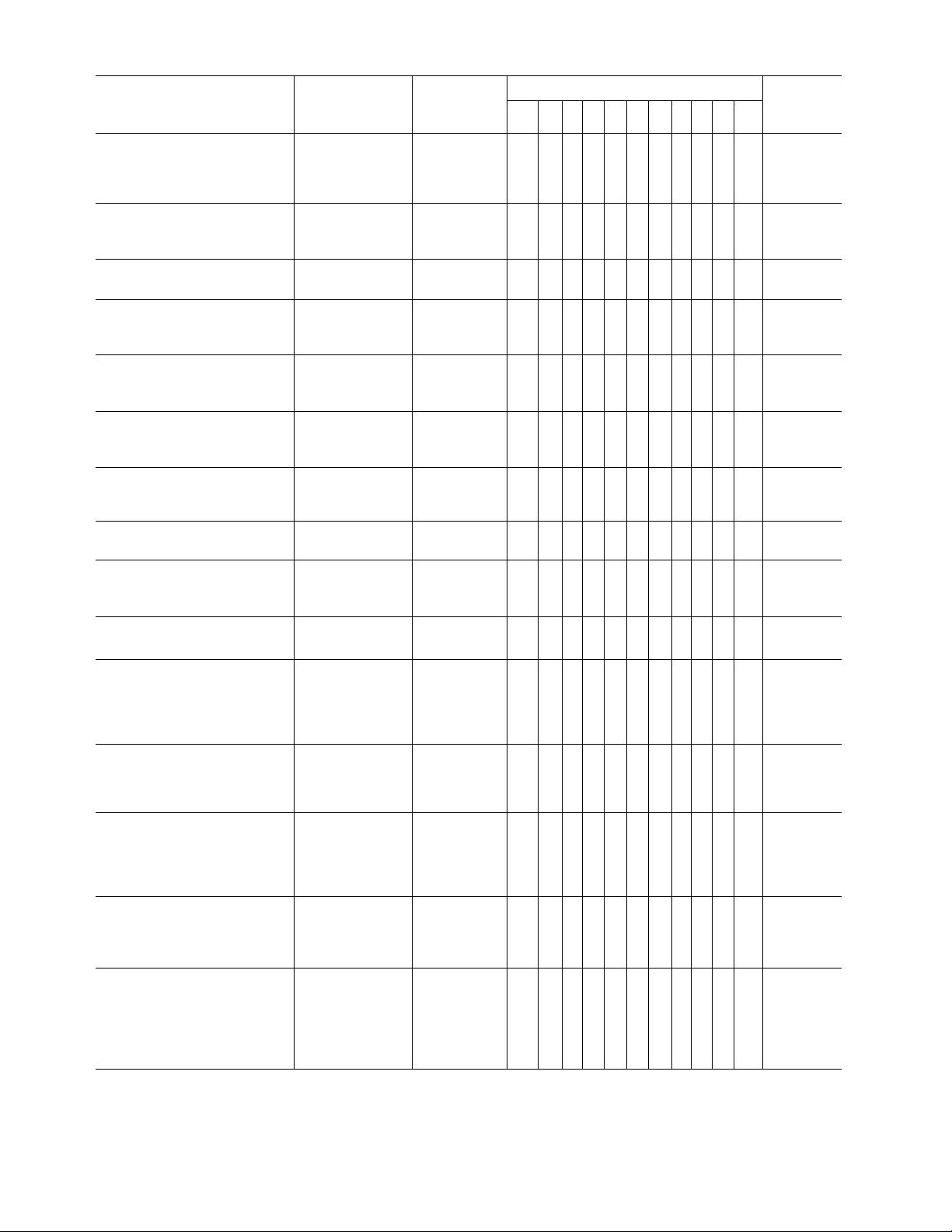
TABLE 1—MODEL SPECIFICATIONS
MODEL AND DESCRIPTION
Q539A Subbases provide system
and fan switching and cooiing
anticipation to controi heating and
cooiing appiications.
Q539A1014, Q539A4026' for
single heating and cooling
transformer applications.
Q539A1022 with impedance
relay reset switch.
Q539A1022 with indicator LED
for impedance relay reset
switch.
Q539A1022 with impedance
relay reset switch for heat
pump applications.
Q539A1121 with special
resistor for gas air conditioning
applications.
Q539A1147, Q539A4000‘ for
applications with isolated heating
and cooling circuits.
Q539A1162 used with W884
Comfort Control Center only.
SYSTEM
SWITCHING
(dpst and dp3t)
COOL-OFF-HEAT ON-AUTO
COOL-OFF-
HEAT-RESET
COOL-OFF-
RESET-HEAT
COOL-OFF-
RESET-HEAT
COOL-OFF-HEAT
COOL-OFF-HEAT ON-AUTO
COOL-OFF-HEAT
FAN
SWITCHING
(spdt)
ON-AUTO
ON-AUTO X X
ON-AUTO
ON-AUTO X X X
ON-AUTO X X X
X X X
X X X
X X X
X
SUBBASE TERMINALS WIRING
X X X
X
X X X X
X
X X
X*
X X
X
G
o X p z
X X
X Fig. 3
X X
X X
Rc R»
X X
DIAGRAMR W Y B
Fig. 1
Fig. 2
Fig.1
Fig. 2
Fig. 1
Fig. 2
Fig. 1
Fig. 2
Fig. 4
Fig. 5
Fig. 1
Fig. 2
Q539A1196 with “G” terminal
isolated on heating for external
low voltage fan switch.
Q539A1394 with indicator LED
for oil burner applications"
Q539B1005 with system
switching and cooling
anticipation for heating and
cooling applications. No fan
switching.
Q539C1020, Q539C4008’' with
system and fan switching and
cooling anticipation for coolingonly applications.
Q539G1000 with system and fan
switching for control of heatingonly system. No cooling
anticipator. Summer fan operation
available.
Q539H1009 with fan switching,
cooling anticipation, and "Z”
terminal for remote AUTO FAN
switching. No system switching.
Q539J1006, Q539J400(y= with
system switching and cooling
antidpation for electric heat and
heat pump applications. Fan
relay controls AUTO FAN
operation.
COOL-OFF-HEAT ON-AUTO
COOL-OFF-HEAT ON-AUTO
COOL-OFF-HEAT
COOL-OFF ON-AUTO
HEAT-OFF ON-AUTO
NONE ON-AUTO X
COOL-OFF-HEAT ON-AUTO
NONE X X X X X
X X X
X X
X X
X X
X X
X X X
X Fig. 6
X
X
X Fig. 8
X X
X
X X X
X X
x“ Fig. 9
X Fig. 10
X
Fig. 7
Fig. 1
Fig. 2
Fig. 11
(continued on next page)
60-2246—4
Page 4
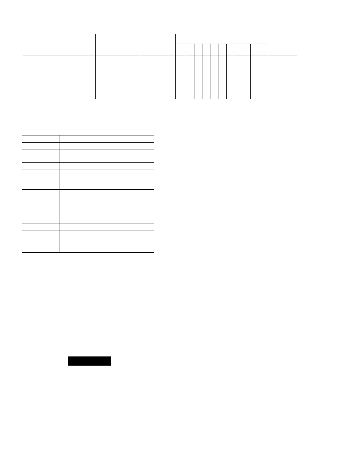
Table 1 (continued)
SYSTEM
MODEL AND DESCRIPTION
Q539J1022 is the same as
Q539J1006 for use in W884E
Comfort Control Center only.
Q539P1018 with wiring terminals
and indicator LED for heatingonly oil burner applications.
“Subbase has “4" terminal which is same as “B" terminal.
’’Rj,terminal for cooling transformer.
“Designer model with textured beige finish.
‘‘Subbase has "1" terminal in place of "Z" terminal.
TABLE 2—TERMINAL DESIGNATIONS“.
TERMINAL
R Transformer.
w
Y Cooling Contactor.
B9(4)«
O®
G
X'
P Heat Pump Contactor Coil.
Z
CONNECTION
Cooling transformer.
Heating transformer.
Heating Relay or Valve.
Heating Damper Motor or Changeover
Valve (if used).
Cooling Damper Motor or Changeover
Valve.
Fan Relay Coil.
Clogged Filter Switch or Lockout Switch
(primary control).
Q539H low voltage fan switch for
control of fan relay in AUTO position for
both heating and cooling control.
SWITCHING
(dpst and dp3t)
COOL-OFF-HEAT ON-AUTO X
NONE NONE X X
FAN
SWITCHING
(spdt)
R W Y B G
SUBBASE TERMINALS
X X
R1, W1, Y1, (or B1) are not marked on thermostat
subbase. They are mounting posts and electrical con
nections for thermostat.
Cooling transformer in systems with isolated heating
and cooling circuits.
Heating transformer in systems with isolated heating
and cooling circuits.
Circuit only completed between "R” and "B” with system
switch in HEAT position: “4” terminal is the same as
Honeywell “B” terminal.
Circuit only completed between “R” and “O” with system
switch in COOL position.
Only available on subbases with indicator lights.
Jumpered to humidity controller in Q539K/T87F
hookup.
X X X
X
O X p z
X Fig. 12
Rc R-
WIRING
DIAGRAM
Fig. 11
INSTALLATION
WHEN INSTALLING THIS PRODUCT...
1. Read these instructions carefully. Failure to follow
instructions can damage product or cause a hazardous
condition.
2. Check ratings given in instructions and on product to
make sure product is suitable for your application.
3. Make sure installer is a trained, experienced service
technician.
4. After completing installation, use these instructions
to check out product operation.
CAUTION
1. Disconnect power supply before beginning in
stallation to prevent electrical shock or equip
ment damage.
2. On systems using a low voltage gas control,
never apply a jumper across the control coil
terminals. This may burn out the thermostat heat
anticipator.
LOCATION
Locate the subbase about 5 ft [1.5 m] above the floor in
an area with good air circulation at average temperature.
Do not mount the subbase where it may be affected
by—
— drafts or dead spots behind doors or in corners.
— hot or cold air from ducts.
— radiant heat from the sun, fireplaces, or appliances.
— concealed pipes and chimneys.
— unheated (uncooled) areas behind the subbase,
such as an outside wall.
MOUNTING AND WIRING
Disconnect power supply before beginning installation
to prevent electrical shock or equipment damage.
All wiring must comply with local codes and ordinances.
1. In replacement applications, check the existing sub
base wires for cracked or frayed insulation. Replace any
wires in poor condition. If the wire is plastered into the wall,
make a hole next to the wires and loosen the wires so that
Page 5

they can be pushed back into the wall later.
2. In new installations, run wiring (if necessary) to the
subbase location.
3. Connect the wires to the terminals inside the sub
base. Refer to equipment manufacturer's instructions for
Q539 wiring diagrams. If not available, refer to Figs. 1
through 12.
4. Push excess wire back through the hole and plug any
opening with insulation to prevent drafts that may affect
performance.
5. Loosely fasten the thermostat subbase to the wall
with a screw through the left mounting hole. Adjust the
subbase so that it is approximately level and start the
second screw through the right mounting slot. Do not
tighten.
6. Level the thermostat subbase using a plumb line or
spirit level as shown in Fig. 13.
7. Tighten mounting screws.
IMPORTANT
This thermostat is calibrated at the factory while
mounted at true level. Any inaccuracy in leveling
during mounting causes control point deviation.
8. Mount and wire the thermostat to the thermostat
subbase by tightening three captive mounting screws on
thermostat. Tightening the three captive mounting screws
completes all electrical connections.
Q539Arr87F
A POWER SUPPLY. PROVIDE DISCONNECT MEANS AND OVERLOAD
PROTECTION AS REQUIRED.
A NO. 4 TERMINAL IS SAME AS B TERMINAL.
M310B
A X TERMINAL USED ON 0539 MODELS WITH FACTORY-INSTALLED
INDICATOR LED.
FIG. 1—Q539A,B,C IN HEATING-COOUNG APPUCATION USING COMMON POWER SUPPLY.
60-2246—4
Page 6

Q539An'87F
HEATING
DAMPER
WITCH
MOTOR
(IF USED)
COOLING
DAMPER
MOTOR
(IF USED)
“1“
A
_C “
■^T
<i) I
-0^1
A
A X TERMINAL IS USED ON 0539 MODELS WITH FACTORY-
INSTALLED INDICATOR LED,
A POWER SUPPLY. PROVIDE DISCONNECT MEANS AND
OVERLOAD PROTECTION AS REQUIRED.
A ISOLATING RELAY.
A VALVE OR RELAY WITH SEPARATE POWER SUPPLY MAY BE USED
IN PLACE OF OIL PRIMARY AS SHOWN BY BROKEN LINE.
FIG. 2—Q539A,B IN HEATING-COOLING APPLICA
TION WITH DAMPER MOTORS AND
ISOLATION RELAY.
Q539ATr87F
A POWER SUPPLY. PROVIDE DISCONNECT MEANS AND OVERLOAD
PROTECTION AS REQUIRED.
A CONNECT VALVE OR RELAY TO O FOR CHANGEOVER IN COOLING
OR B FOR CHANGEOVER IN HEATING.
A X TERMINAL IS USED ON Q539 MODELS WITH FACTORY-INSTALLED
INDICATOR LED.
A RECOMMENDED HEAT ANTICIPATOR SETTING ON HEAT PUMPS IS
140% OF THE TOTAL COMBINED CURRENT DRAW OF THE FAN AND
COMPRESSOR RELAYS. STANDARD HEATING SYSTEMS CYCLE AT
5 TO 6 CPH AND HEAT PUMP SYSTEMS CYCLE AT 2.5 TO 3 CPH ON
EITHER HEATING OR COOLING. ^
FIG. 3—Q539A IN HEAT PUMP APPLICATION.
/K POWER SUPPLY. PROVIDE DISCONNECT MEANS AND OVERLOAD
PROTECTION AS REQUIRED.
Ak valve or relay with separate power supply may BE USED
IN PLACE OF OIL PRIMARY AS SHOWN BY BROKEN LINE.
A\ THIS SUBBASEH-HERMOSTAT COMBINATION IS ALSO USED WITH
ELECTRIC HEATING COMPONENTS OR PANELS USING BOTH AC
AND DC CONTROL CIRCUITS.
FIG. 4—Q539A1147 IN HEATING-COOLING APPLICATION WITH ISOLATED CIRCUITS.
Page 7

-EXAMPLE;FOR Rc TO Rh JUMPER.
STRIP WIRE END LONG ENOUGH
TO JOIN BOTH TERMINALS.
FIG. 5-JUMPER "R^" AND "R„" TERMINALS FOR
COMMON HEATING-COOLING TRANS
FORMER IN Q539A1147.
Q538WTe7F
A POWER SUPPLY. PROVIDE DISCONNECT MEANS AND OVERLOAD
PROTECTION AS REQUIRED.
LOW VOLTAGE EXTERNAL FAN SWITCH FOR CONTROL OF AUTO
A
FAN DURING HEATING. u,™
FIG. 6—Q539A IN TYPICAL HOOKUP.
a539A/T87F
A POWER SUPPLY. PROVIDE DISCONNECT MEANS AND OVERLOAD
PROTECTION AS REQUIRED.
FIG. 7—Q539A IN HEATING-COOLING APPLICATION
WITH INDICATOR LED.
A POWER SUPPLY. PROVIDE DISCONNECT MEANS AND OVERLOAD
PROTECTION AS REQUIRED.
A X TERMINAL USED ON 0539 MODELS WITH FACTORY-INSTALLED
INDICATOR LED. .....
FIG. 8—Q539C IN COOLING-ONLY APPLICATION.
7 60-2246-4
Page 8

PROTECTION AS REQUIRED.
^JUMPER FOR AUTO FAN IN ELECTRIC HEAT APPLICATIONS. IF
És
JUMPER IS USED. MEASURE COMBINED “HEAT RELAY" AND
"FAN RELAY" CURRENT RATINGS.
A
3\ RECOMMENDED HEAT ANTICIPATOR SETTING IS THE COMBINED
CURRENT DRAW OF THE FAN RELAY AND HEAT RELAY AS THE FAN
RELAY CURRENT PASSES THROUGH THE HEAT ANTICIPATOR.
M2162
FAN
RELAY
HEATING
RELAY OR
VALVE
SWITCH
I______________________
A X TERMINAL IS USED ON 0539 MODELS WITH FACTORY-!NSTAUED
INDICATOR LED.
A POWER SUPPLY. PROVIDE DISCONNECT MEANS AND OVERLOAD
PROTECTION AS REQUIRED.
COOLING
CONTACTOR
EXTERNAL
SWITCHING
FOR
AUTO FAN
Fig. 9—Q539G IN HEATING APPLICATION
AUTOMATIC FAN OPERATION.
WITH
Fig. 10—Q539H IN HEATING-COOLING APPLICATION
AND AUTOMATIC FAN OPERATION
SWITCHING.
^1\ X TERMINAL IS USED ON Q539 MODELS WITH FACTORY-INSTALLED
A
INDICATOR LED.
WITH NO O TERMINAL LOAD. THERMOSTAT CURRENT DURING HEATING
A
CYCLE VARIES DEPENDING ON WHETHER FAN SWITCH IS IN THE ON OR
AUTO POSITION. HEATER SHOULD BE SET FOR COMBINED CURRENT
LEVEL OF HEAT RELAY AND FAN RELAY COILS. WITH O TERMINAL
LOAD. SET THERMOSTAT HEAT ANTICIPATOR TO ITS MAXIMUM
SETTING AS COOLING ANTICIPATOR IN SERIES WITH 0 TERMINAL
LOAD PROVIDES HEAT ANTICIPATION IN THE HEATING CYCLE. (LIMIT
THE THERMOSTAT HEATING LOAD CURRENT TO 0.8 AMPS TO ASSURE
GOOD PERFORMANCE.)
POWER SUPPLY. PROVIDE DISCONNECT MEANS AND OVERLOAD
A
PROTECTION AS REQUIRED.
Fig. 11—Q539J IN HEATING-COOLING APPLICATION WITH AUTO FAN OPERATION.
Page 9

Q539P/T87F
MOLDED
POST (2)
VERTICAL
PLUMP
I LINE
POWER SUPPLY. PROVIDE DISCONNECT MEANS AND OVERLOAD
A
PROTECTION AS REQUIRED.
Fig. 12—Q539P IN HEATING-ONLY SYSTEM WITH
REMOTE LOCKOUT INDICATION.
M1029A
CHECKOUT
NOTE; When adding a subbase to a thermostat with
positive OFF, make certain the positive OFF switch on
the thermostat is in the ON position so the system can
be manually controlled from the subbase system
switch.
When installation is complete, turn on power supply and
check system operation as follows:
SUBBASES WITH SYSTEM OR FAN SWITCHING
1. With 0539 system switch (or remote system switch)
set at HEAT and fan switch set at AUTO, turn the thermo
stat dial at least 5° F [3° C] above room temperature.
Heating should start immediately; the fan should start after
a short delay (immediately with Q539G (with jumper) or
Q539J).
2. With 0539 system switch (or remote system switch)
set at COOL and fan switch set at AUTO, turn the thermo
stat dial at least 5° F [3° C] below room temperature.
Cooling and fan should start. (External switch must be
made in Q539H hookup.)
OPENING FOR
THERMOSTAT ,
WIRING
I ' VERTICAL
I GUIDE
0
Fig. 13—LEVEL 0539 USING A SPIRIT LEVEL OR
PLUM LINE (dimensions are In In. [mm]).
3. Set system switch at OFF and fan switch at FAN ON.
Fan should run continuously. Turn thermostat 5“ F [3® C]
below room temperature. Heating and cooling equipment
cannot be actuated by the thermostat (except in system
with dpst remote changeover switch.
4. Operate entire system at least one complete cycle
with switches in each position before leaving installation.
Turn thermostat dial to the desired setting and move the
system and fan switches to their desired positions.
SUBBASE WITHOUT MANUAL SWITCHES (Q539P)
1. On Q539P subbase, turn thermostat dial 5° F [3° C]
above room temperature to call for heat. Heating should
start immediately, the fan should start after a short delay.
2. Turn thermostat dial 5® F [3® C] below room tempera
ture. Heating and fan should shut off.
3. Operate the entire system at least one complete
cycle before leaving installation. Turn thermostat dial to the
desired setting.
60-2246—4
Page 10

OPERATION
The Q539 Subbase provides cooling anticipation, wir
ing terminals, mounting base, and system and fan switch
ing for the T87F Thermostat.
The Q539 Subbase mounts directly to the wall using
two mounting screws. The T87F Thermostat mounts to the
Q539 Subbase using three captive screws. Tightening
these screws into the subbase also completes all electrical
connections between the subbase and the thermostat.
The HEAT-OFF-COOL system switch selects either
heating or cooling or turns the system off. The FAN-ONAUTO fan switch either sets the fan to turn on automatically
during heating or cooling or allows the fan to run continu
ously.
10
Page 11

NOTES
—
11
60-2246—4
Page 12

Honeywell Inc.
1885 Douglas Drive N.
International Sales Offices in all principal cities of the world. Manufacturing in
Australia, Canada, Finland, France, Germany, Japan, Mexico, Netherlands,
Golden Valley, MN 55422-4386 Spain, Taiwan, United Kingdom, U.S.A.
PRINTED IN U S A.
QUALITY IS KEY
 Loading...