

Page 1
38-00020-02
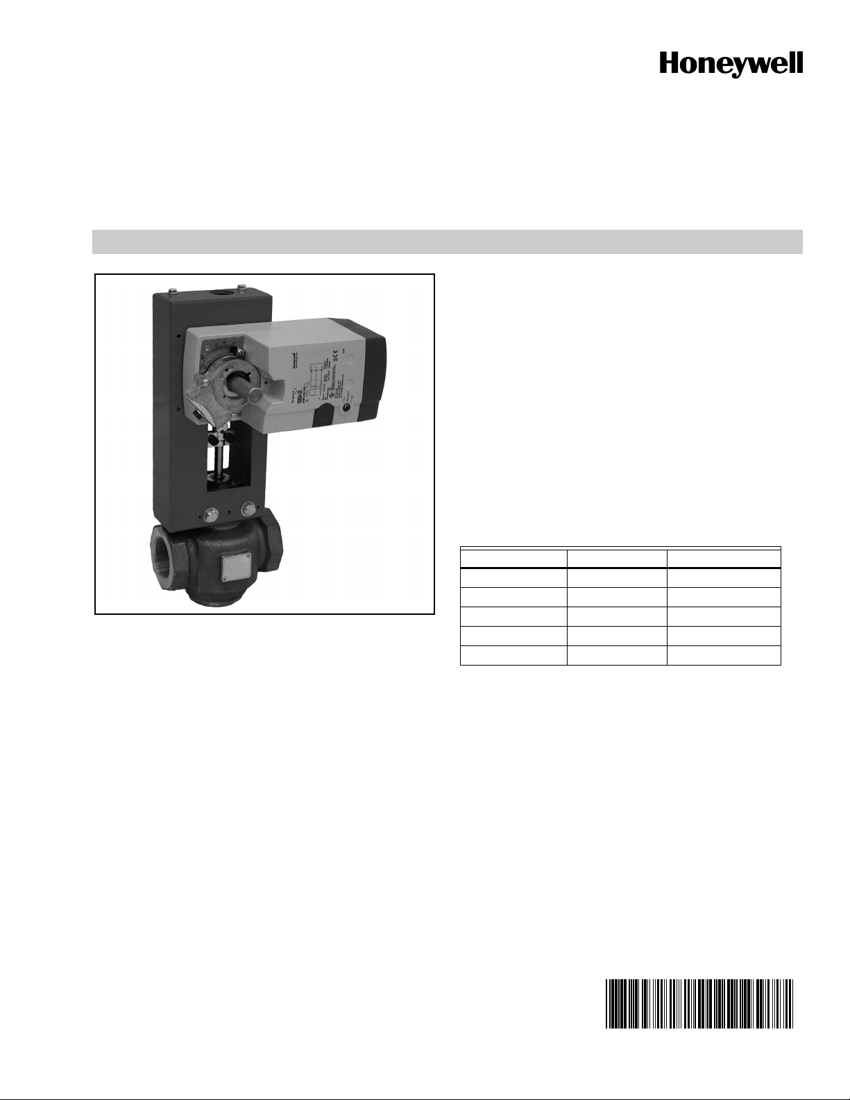
Q5024A,B
Globe Valve Linkages
FOR DIRECT COUPLED ACTUATORS
• Heavy-duty steel rack and pinion construction and
aluminum die-cast housing.
• Maintenance-free construction.
• Flexible actuator mounting orientation.
• Adjustable manual override lever and valve position
indicator.
• Available for 1/2” through 6” globe valves made by
most manufacturers.
• Used with Honeywell MS and MN Spring and NonSpring Actuators.
SPECIFICATIONS
Models: See Table 1.
PRODUCT DATA
APPLICATION
Q5024 globe valve linkages connect a Honeywell direct
coupled actuator (DCA) to a steam or water globe valve.
Q5024 linkages are compatible with 2- and 3-way globe
valves.
FEATURES
• Used with 2-way and 3-way globe valves in modulating
or two-position service.
• Quick and simple installation with no disassembly
required.
Table 1. Models.
Linkage Actuator Qty* Valve Stroke**
Q5024A1116 1 0.63” / 16 mm
Q5024A1123 1 0.91” / 23 mm
Q5024A1130 1 1.18” / 30 mm
Q5024B2230 2 1.18” / 30 mm
Q5024B2240 2 1.57” / 40 mm
* See Table 3 for Linkage and Actuator selection.
** If the exact stroke is not available than round up to the next
higher stroke.
Dimensions: See Fig. 1.
Temperature Range:
Ambient Range: -40°F to 140°F (-40°C to 60°C).
Materials of Construction:
Housing: Cold Rolled Steel
Rack and Pinion Gears: Steel
Bushing and Clip: Brass
Contents
Application .............................................................. 1
Specifications ......................................................... 1
Installation .............................................................. 13
Checkout ................................................................ 14
Special Order Form ................................................. 15
Page 2
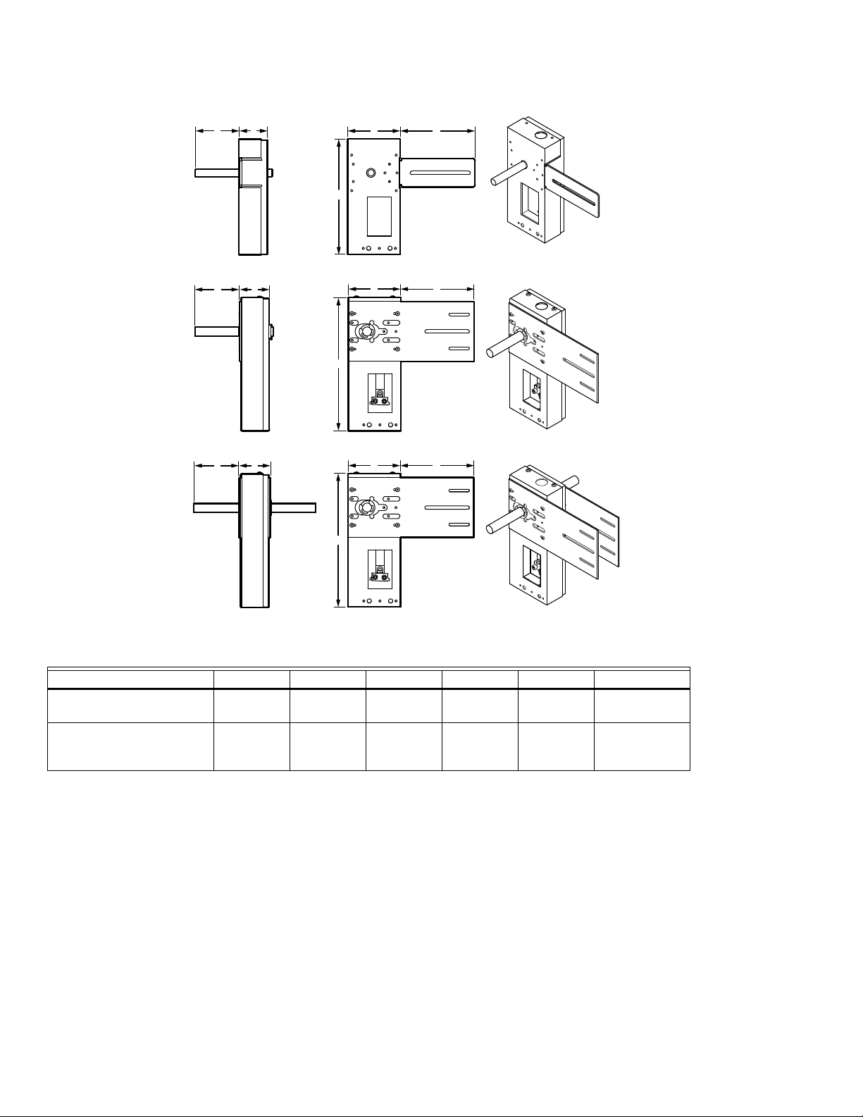
GLOBE VALVE LINKAGES
Q5024A1116/Q5024A1123
E
B
E
B
Q5024B2230/Q5024B2240
E
B
A
D
Q5024A1130
A
D
A
C
C
C
D
M35307
Fig. 1. Q5024 Dimensions.
Table 2. Dimensions in Inches.
Linkage ABCDEShaft Dia.
Q5024A1116
4-3/8” 3-1/2” 6-1/4” 9-1/2” 2-1/2” 16mm
Q5024A1123
Q5024A1130
4-3/8” 4” 6” 11” 2-3/8” 19mm
Q5024B2230
Q5024B2240
ORDERING INFORMATION
When purchasing replacement and modernization products from your TRADELINE® wholesaler or distributor, refer to the
TRADELINE® Catalog or price sheets for complete ordering number. If you have additional questions, need further information,
or would like to comment on our products or services, please write or phone:
1. Your local Honeywell Environmental and Combustion Controls Sales Office (check white pages of your phone directory).
2. Honeywell Customer Care
Golden Valley, Minnesota 55422-4386
3. http:// or http://customer.honeywell.ca
International Sales and Service Offices in all principal cities of the world. Manufacturing in Belgium, Canada, China, Czech
Republic, Germany, Hungary, Italy, Mexico, Netherlands, United Kingdom, and United States.
38-00020—02 2
Page 3
GLOBE VALVE LINKAGES
LINKAGE SELECTION INSTRUCTION
When selecting your linkage look at the Table 3 for the valve model list. Select the correct valve size to see the recommended
linkage and bonnet adapter. Choose the correct actuator torque based on necessary close-off pressure. If model you are looking
for is not listed fill out the Special Order Form located below.
If you do not have the exact part number or valve size, measure the valve stroke and select the corresponding linkage from Table 1.
Next, select the appropriate bonnet adapter kit from Table 5. This kit includes variety of bonnet adapters for you to choose from at
the job site.
Manufacturer Valve Model Single Actuator Linkage
Honeywell V5011
V5013
VGF Single Actuator Linkage
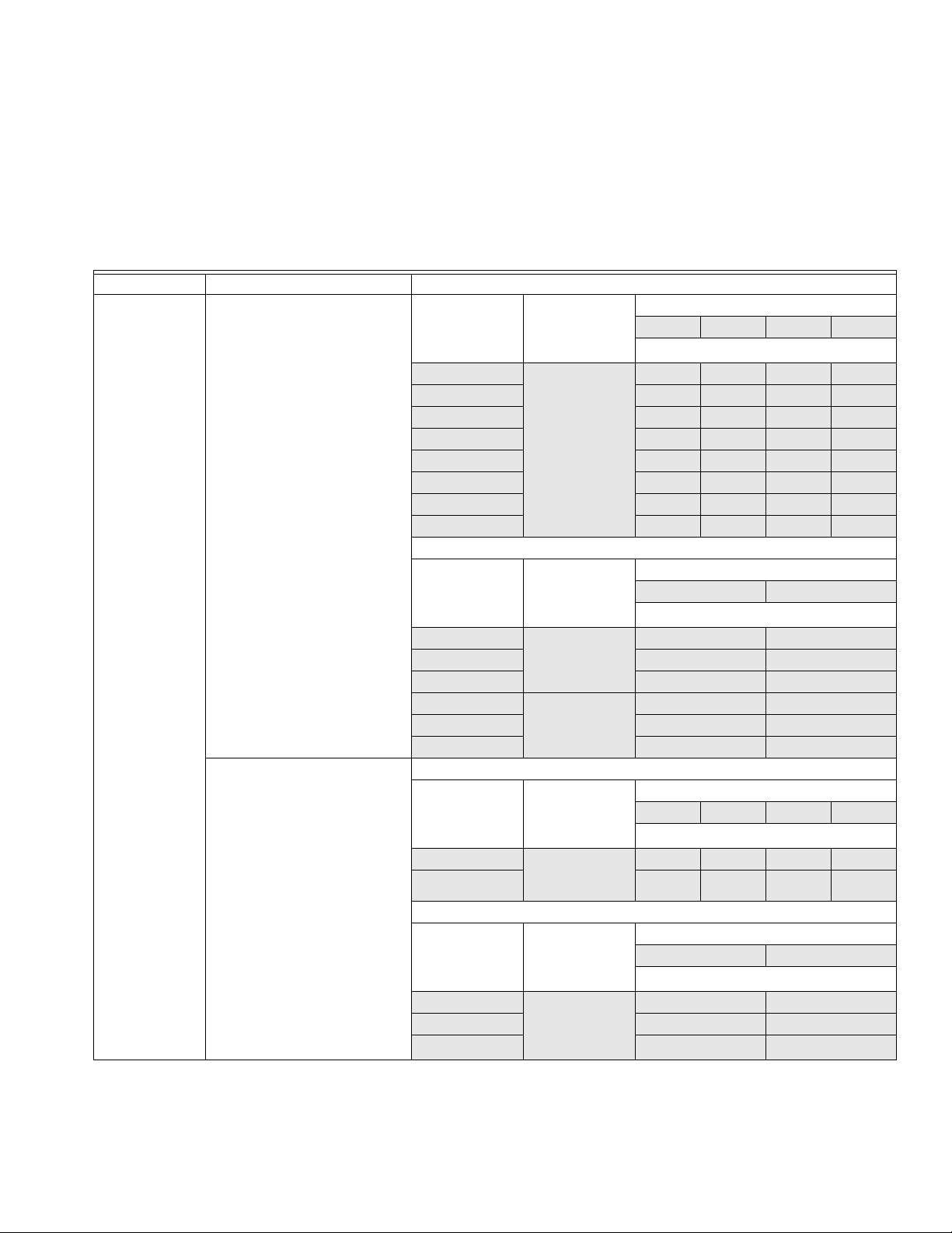
Table 3. Linkage and Actuator Selection.
Val ve
Connection
Size
(inch)
0.5 Q5024A1123
0.75 130 230
1 80 140 230
1.25 50 90 200
1.5 65 140
2 35 80 140
2.5 55 90
3 35 65
Val ve
Connection
Size
(inch)
2 Q5024B2230
2.5 75 123
3 50 80
4 Q5024B2240
5 12 21
6 10 16
Val ve
Connection
Size
(inch)
2.5 Q5024A1123
3
Val ve
Connection
Size
(inch)
4 Q5024B2240
5 11 18
6
Linkage and
Bonnet Adapter
and
HU5024-001
Dual Actuator Linkage
Linkage and
Bonnet Adapter
and
HU5024-001
and
HU5024-002
Linkage and
Bonnet Adapter
and
HU5024-001
Dual Actuator Linkage
Linkage and
Bonnet Adapter
and
HU5024-002
Actuator Torque (lb-in)
44 88 175 300
Close-Off (psi)
230 230
Actuator Torque (lb-in)
350 (2 x 175) 600 (2 x 300)
Close-Off (psi)
118
18 38
Actuator Torque (lb-in)
44 88 175 300
Close-Off (psi)
52 88
26 42
Actuator Torque (lb-in)
350 (2 x 175) 600 (2 x 300)
Close-Off (psi)
27 47
11 18
3 38-00020—02
Page 4
GLOBE VALVE LINKAGES
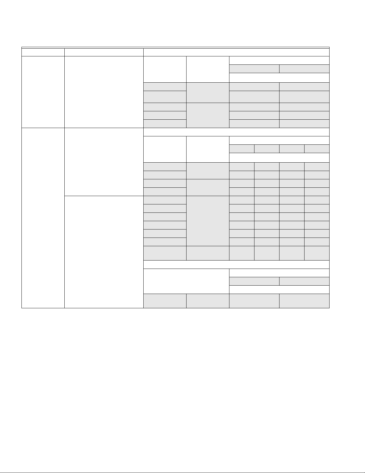
Table 3. Linkage and Actuator Selection. (Continued)
Manufacturer Valve Model Dual Actuator Linkage
Honeywell
(continued)
VGF Pressure Balanced Valve
Connection
Size
Linkage and
Bonnet Adapter
350 (2 x 175) 600 (2 x 300)
(inch)
2.5 Q5024B2230
3 175 175
and
HU5024-002
4 Q5024B2240
5 175 175
and
HU5024-002
175 175
175 175
6 175 175
Johnson
Control
V90AD-1C thru 7C
V90DD-1C thru 7C
Val ve
Connection
Size
Single Actuator Linkage
Linkage and
Bonnet Adapter
44 88 175 300
(inch)
0.5 Q5024A1116
0.75 165 230
and JU5024-005
1 Q5024A1123
1.5 65 140
and JU5024-005
V90CA-1 thru 8 0.5 Q5024A1123
0.75 130 230
and JU5024-005
230 230
80 140
230 230
1 80 140 230
1.25 50 90 200
1.5 65 140
2 35 80 140
2.5 Q5024A1123
and JU5024-002
Dual Actuator Linkage
350 (2 x 175) 600 (2 x 300)
3 Q5024B2230
and JU5024-002
Actuator Torque (lb-in)
Close-Off (psi)
Actuator Torque (lb-in)
Close-Off (psi)
55 90
Actuator Torque (lb-in)
Close-Off (psi)
50 80
38-00020—02 4
Page 5
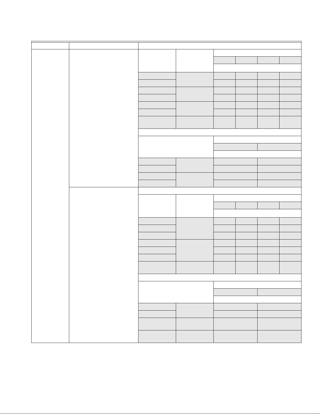
Table 3. Linkage and Actuator Selection. (Continued)
Manufacturer Valve Model Single Actuator Linkage
Johnson
Control
(continued)
VG7000/2000 Series Valve
Connection
Size
(inch)
0.5 Q5024A1116
0.75 165 230
1 Q5024A1116
1.25 65 120
Linkage and
Bonnet Adapter
and JU5024-001
and JU5024-003
Actuator Torque (lb-in)
44 88 175 300
Close-Off (psi)
230 230
100 190
1.5 Q5024A1123
2 35 80 140
and JU5024-003
2.5 Q5024A1123
and JU5024-004
Dual Actuator Linkage
Actuator Torque (lb-in)
350 (2 x 175) 600 (2 x 300)
Close-Off (psi)
VTM Series
VB-3752
3 Q5024B2230
4 18 48
and JU5024-004
5 Q5024B2240and
6 10 16
JU5024-004
Single Actuator Linkage
Val ve
Connection
Linkage and
Bonnet Adapter
Size
(inch)
0.5 Q5024A1116
0.75 165 230
and JU5024-005
50 80
12 21
Actuator Torque (lb-in)
44 88 175 300
Close-Off (psi)
230 230
1 100 190
1.25 Q5024A1123
1.5 65 140
and JU5024-005
50 90
2 35 80 140
2.5 Q5024A1123
and JU5024-002
Dual Actuator Linkage
Actuator Torque (lb-in)
350 (2 x 175) 600 (2 x 300)
Close-Off (psi)
3 Q5024B2230
4 18 48
and JU5024-002
5 Q5024B2240
50 80
12 21
and JU5024-006
6 Q5024B2240
10 16
and JU5024-004
GLOBE VALVE LINKAGES
65 140
55 90
55 90
5 38-00020—02
Page 6

GLOBE VALVE LINKAGES
Table 3. Linkage and Actuator Selection. (Continued)
Manufacturer Valve Model Single Actuator Linkage
Johnson
Control
(continued)
VB-3754-1 thru 8
VB-3970
Val ve
Connection
Size
Linkage and
Bonnet Adapter
Actuator Torque (lb-in)
44 88 175 300
(inch)
0.5 Q5024A1116
0.75 165 230
and JU5024-005
1 Q5024A1123
1.25 50 90 200
and JU5024-005
230 230
80 140
1.5 65 140
2 35 80 140
2.5 Q5024A1123
and JU5024-002
Dual Actuator Linkage
Actuator Torque (lb-in)
350 (2 x 175) 600 (2 x 300)
VB-3954-1 thru 7
VB-4324-1 thru 7
VB-4322
3 Q5024B2230
4 18 48
and JU5024-002
5 Q5024B2240
6 10 16
and JU5024-006
Single Actuator Linkage
Val ve
Connection
Linkage and
Bonnet Adapter
Size
50 80
12 21
Actuator Torque (lb-in)
44 88 175 300
(inch)
0.5 Q5024A1116
0.75 165 230
and JU5024-005
1 Q5024A1123
1.25 50 90 200
and JU5024-005
230 230
80 140
1.5 65 140
2 35 80 140
2.5 Q5024A1123
and JU5024-002
Dual Actuator Linkage
Actuator Torque (lb-in)
350 (2 x 175) 600 (2 x 300)
3 Q5024B2230
4 18 48
and JU5024-002
5 Q5024B2240
6 10 16
and JU5024-006
50 80
12 21
Close-Off (psi)
55 90
Close-Off (psi)
Close-Off (psi)
55 90
Close-Off (psi)
38-00020—02 6
Page 7

Table 3. Linkage and Actuator Selection. (Continued)
Manufacturer Valve Model Single Actuator Linkage
Johnson
Control
(continued)
V-5462 Valve
Connection
Size
(inch)
Linkage and
Bonnet Adapter
Actuator Torque (lb-in)
44 88 175 300
Close-Off (psi)
2.5 Q5024A1123
and JU5024-006
Dual Actuator Linkage
Actuator Torque (lb-in)
350 (2 x 175) 600 (2 x 300)
Close-Off (psi)
Siemens
Landis
Powers
3 Q5024B2230
4 18 48
and JU5024-006
5 Q5024B2240
6 10 16
and JU5024-006
591 (3 way) Single Actuator Linkage
Val ve
Connection
Linkage and
Bonnet Adapter
Size
(inch)
50 80
12 21
Actuator Torque (lb-in)
44 88 175 300
Close-Off (psi)
1.5 Q5024A1116
2 45
and
GU5024-002
2.5 Q5024A1123
3 35 65
and
GU5024-003
Dual Actuator Linkage
Actuator Torque (lb-in)
350 (2 x 175) 600 (2 x 300)
Close-Off (psi)
4 Q5024B2230
18 48
and
GU5024-003
5 Q5024B2240
6 10 16
and
GU5024-003
12 21
GLOBE VALVE LINKAGES
55 90
85
55 90
7 38-00020—02
Page 8

GLOBE VALVE LINKAGES
Table 3. Linkage and Actuator Selection. (Continued)
Manufacturer Valve Model Single Actuator Linkage
Siemens
Landis
Powers
(continued)
591 (2 way) Valve
Connection
Size
(inch)
Linkage and
Bonnet Adapter
Actuator Torque (lb-in)
44 88 175 300
1.5 Q5024A1130
2 30 60 105
and
GU5024-002
2.5 Q5024A1123
3 35 65
and
GU5024-003
Dual Actuator Linkage
Actuator Torque (lb-in)
350 (2 x 175) 600 (2 x 300)
4 Q5024B2230
18 48
and
GU5024-003
599
(Linkage Only: No Bonnet
Adapter Necessary)
5 Q5024B2240
6 10 16
and
GU5024-003
Single Actuator Linkage
Val ve
Linkage Actuator Torque (lb-in)
Connection
Size
12 21
44 88 175 300
(inch)
0.5 Q5024A1123 230 230
0.75 130 230
1 80 140 230
1.25 50 90 200
1.5 65 140
2 35 80 140
2.5 55 90
3 35 65
Dual Actuator Linkage
Actuator Torque (lb-in)
350 (2 x 175) 600 (2 x 300)
4 Q5024B2240 18 38
5 12 21
6 10 16
658 Single Actuator Linkage
Val ve
Connection
Size
Linkage and
Bonnet Adapter
Actuator Torque (lb-in)
44 88 175 300
(inch)
0.5 Q5024A1116
0.75 165 230
and
GU5024-001
230 230
1 100 190
1.25 65 120
Close-Off (psi)
50 105
55 90
Close-Off (psi)
Close-Off (psi)
Close-Off (psi)
Close-Off (psi)
38-00020—02 8
Page 9

Table 3. Linkage and Actuator Selection. (Continued)
Manufacturer Valve Model Single Actuator Linkage
Siebe
Barber Colman
Invensys
VB-111 Series Valve
Connection
Size
Linkage and
Bonnet Adapter
Actuator Torque (lb-in)
44 88 175 300
(inch)
0.5 Q5024A1116
0.75 165 230
and BU5024-001
230 230
1 100 190
1.25 65 120
VB-921 Series Single Actuator Linkage
Val ve
Connection
Size
Linkage and
Bonnet Adapter
Actuator Torque (lb-in)
44 88 175 300
(inch)
0.5 Q5024A1116
0.75 165 230
and BU5024-001
230 230
1 100 190
1.25 65 120
1.5 Q5024A1130
2 30 60 105
and BU5024-002
Dual Actuator Linkage
Actuator Torque (lb-in)
350 (2 x 175) 600 (2 x 300)
2.5 Q5024B2230
75 123
and BU5024-003
3 Q5024B2240
37 60
and BU5024-003
VB-922 Series
VB-925 Series
VB-926 Series
Val ve
Connection
Size
Linkage and
Bonnet Adapter
Single Actuator Linkage
Actuator Torque (lb-in)
44 88 175 300
(inch)
0.5 Q5024A1116
0.75 165 230
and BU5024-001
230 230
1 100 190
1.25 65 120
1.5 Q5024A1130
2 30 60 105
and BU5024-002
Dual Actuator Linkage
Actuator Torque (lb-in)
350 (2 x 175) 600 (2 x 300)
2.5 Q5024B2230
3 50 80
and BU5024-003
75 123
GLOBE VALVE LINKAGES
Close-Off (psi)
Close-Off (psi)
50 105
Close-Off (psi)
Close-Off (psi)
50 105
Close-Off (psi)
9 38-00020—02
Page 10

GLOBE VALVE LINKAGES
Table 3. Linkage and Actuator Selection. (Continued)
Manufacturer Valve Model Single Actuator Linkage
Siebe
Barber Colman
Invensys
(continued)
VB-927 Series
VB-928 Series
Val ve
Connection
Size
Linkage and
Bonnet Adapter
Actuator Torque (lb-in)
44 88 175 300
(inch)
0.5 Q5024A1116
0.75 165 230
and BU5024-001
230 230
1 100 190
1.25 65 120
1.5 Q5024A1130
2 30 60 105
and BU5024-002
VB-931 Series Single Actuator Linkage
Val ve
Connection
Size
Linkage and
Bonnet Adapter
Actuator Torque (lb-in)
44 88 175 300
(inch)
0.5 Q5024A1116
0.75 165 230
and BU5024-001
230 230
1 100 190
1.25 65 120
1.5 Q5024A1130
2 30 60 105
and BU5024-002
Dual Actuator Linkage
Actuator Torque (lb-in)
350 (2 x 175) 600 (2 x 300)
2.5 Q5024B2230
3 50 80
and BU5024-003
4 Q5024B2240
75 123
18 38
and BU5024-003
Close-Off (psi)
50 105
Close-Off (psi)
50 105
Close-Off (psi)
38-00020—02 10
Page 11

Table 3. Linkage and Actuator Selection. (Continued)
Manufacturer Valve Model Single Actuator Linkage
Siebe
Barber Colman
Invensys
(continued)
VB-932 Series Valve
Connection
Size
(inch)
0.5 Q5024A1116
0.75 165 230
Linkage and
Bonnet Adapter
and BU5024-001
Actuator Torque (lb-in)
44 88 175 300
230 230
1 100 190
1.25 65 120
1.5 Q5024A1130
2 30 60 105
and BU5024-002
2.5 Q5024A1123
3 35 65
and
WU5024-001
Dual Actuator Linkage
Actuator Torque (lb-in)
350 (2 x 175) 600 (2 x 300)
4 Q5024B2230
5 18 27
and
WU5024-001
6 Q5024B2240
25 48
11 16
and
WU5024-001
VB-7213
VB-7313
Val ve
Connection
Size
Linkage and
Bonnet Adapter
Single Actuator Linkage
Actuator Torque (lb-in)
44 88 175 300
(inch)
0.5 Q5024A1116
0.75 165 230
and BU5024-001
230 230
1 100 190
1.25 65 120
1.5 85
2 45
Belimo G- series Single Actuator Linkage
Val ve
Connection
Size
Linkage and
Bonnet Adapter
Actuator Torque (lb-in)
44 88 175 300
(inch)
0.5 Q5024A1116
0.75 165 230
and
BU5024-001
230 230
1 100 190
1.25 65 120
1.5 85
2 45
GLOBE VALVE LINKAGES
Close-Off (psi)
50 105
55 90
Close-Off (psi)
Close-Off (psi)
Close-Off (psi)
NOTE: If your valve is not listed above fill out Special Order Form located below.
NOTE: The listed close-off pressures are estimated numbers only.
NOTE: The information in this table is based on publicly available information as of the date of this publication. Honey-
well is not liable if information is found to be incorrect
11 38-00020—02
Page 12

GLOBE VALVE LINKAGES
Table 4. Bonnet and Stem Adapters.
Manufacturer Part Number Description
Johnson Controls JU5024-001/U Bonnet adapter 20mm diameter -1.5mm thread pitch with 1/4"-28 TPI* stem adapter
JU5024-002/U Bonnet adapter 1-1/16” diameter-16 TPI with 3/8"-24 TPI stem adapter
JU5024-003/U Bonnet adapter 28mm diameter-1.5mm thread pitch with 1/4"-28 TPI stem adapter
JU5024-004/U Bonnet adapter 3/4" diameter-16 TPI with 3/8"-24 TPI stem adapter
JU5024-005/U Bonnet adapter 3/4" diameter- 18 TPI with 1/4"-28 TPI stem adapter
JU5024-006/U Bonnet adapter 1.59" diameter-14 TPI with 1/2"-20 TPI and 3/8"-24 TPI stem adapter
Siemens, Landis
Powers
GU5024-001/U Bonnet adapter 1-5/16" diameter with 1/4"-28 TPI stem adapter
GU5024-002/U Bonnet adapter 1-3/32" diameter-14 with 3/8"-24 TPI and 1/4"-28 TPI stem adapters
GU5024-003/U Bonnet adapter 1-3/8" diameter - 20 TPI with 3/8"-24 and 1/4"-28 TPI stem adapters
Siebe,
Barber Colman,
Invensys
BU5024-001/U Bonnet adapter 1-1/4" diameter-16 TPI with 1/4"-28 TPI stem adapter
BU5024-002/U Bonnet adapter 1" diameter - 16 TPI with 5/16"-24 TPI stem adapter
BU5024-003/U Bonnet adapter 1-1/4" diameter - 16 TPI with 1/2"-20 TPI stem adapter
WU5024-001/U Bonnet adapter 1-3/8" diameter -18 TPI with 3/8"-24 TPI stem adapter
Honeywell HU5024-001/U Bonnet adapter 1-3/8" diameter with 1/4"-28 TPI stem adapter
HU5024-002/U Bonnet adapter 1-7/8" diameter with 1/2"-20 TPI stem adapter
* TPI - threads per inch
NOTE: If you require a different length stem adapter fill out the Special Order Form located below.
Table 5. Bonnet Adapter Kits.
Kit Part Number Description Contents
JU5024-NPTKIT/U Globe Valve Adapter kit for JCI NPT Valves (1/2" - 2") JU5024-001*, JU5024-003*, JU5024-005*
bonnet adapter, 1 of 1/4"-28 TPI stem adapter
JU5024-FLGKIT/U Globe Valve Adapter kit for JCI Flange Valves (2.5" - 6") JU5024-002*, JU5024-004* bonnet adapter,
1 of 3/8"-24 TPI and 1/2"-20 TPI stem
adapters
GU5024-KIT/U Globe Valve Adapter kit for Siemens, Landis Powers
(1/2" - 6")
GU5024-001*, GU5024-002*, GU5024-003*
bonnet adapter, 1 of 1/4"-28 TPI and
1 of 3/8"-24 TPI stem adapters
BU5024-NPTKIT/U Globe Valve Adapter kit for Siebe, Barber Coleman, Invensys
NPT Valves (1/2" - 2")
BU5024-FLGKIT/U Globe Valve Adapter kit for Siebe, Barber Coleman, Invensys
(2.5" - 6) Flange Valves
BU5024-001*, BU5024-002* bonnet adapter,
1 of 1/4"-28 TPI stem adapter
BU5024-003*, WU5024-001* bonnet adapter,
1 of 3/8"-24 TPI and 1 of 1/2"-20 TPI stem
adapters
* Bonnet adapter only. For sizing see Table 4.
38-00020—02 12
Page 13

GLOBE VALVE LINKAGES
M35309
STEP 2
INSTALLATION
When Installing this Product...
1. Read these instructions carefully. Failure to follow them
could damage the product or cause a hazardous
condition.
2. Check the ratings given in the instructions and on the
product to make sure that the product is suitable for your
application.
3. Installer must be a trained, experienced service
technician.
4. After installation is complete, verify product
operation as provided in these instructions.
Location
Select a location in which the valve, linkage, and motor will be
within the environmental and ambient temperature ratings. See
the specifications section.
NOTE: Allow approximately 12 in. clearance above the valve
bonnet for installation and servicing.
Mounting
IMPORTANT
1. Ensure the valve stem stroke matches the Q5024
linkage. See Table 1.
2. Mounting the Q5024 on a non-Honeywell valve
requires the correct bonnet and stem adapter. See
Table 4.
9. Verify that the valve stem stroke direction and the actuator rotation direction are properly related. For example,
assume a spring return actuator and a 2-way, stem down
to close, normally-closed valve are used together. With
an unpowered actuator, the valve should be fully closed.
To accomplish this rotate the actuator arm on the linkage
fully counterclockwise. This moves the valve stem fully
downward so that when the actuator turns counterclockwise the valve will close.
10. Mount the actuator onto the actuator arm approximately
five degrees from its end stop with the valve fully seated.
This ensures that the actuator closes the valve before it
reaches its end-stop.
11. Place the anti-rotation pin into the bracket slot (see step
5), and slide into the notch on the rear of the actuator.
Next secure the actuator to the actuator arm and finish
by tightening the anti-rotation nut. Complete installation
with wiring the actuator.
LINKAGE INSTALLATION
1. Remove any existing linkages then screw the jam nut
and stem adapter onto the valve stem.
STEP 1
STEM
ADAPTER
JAM NUT
(IF USED)
Installation
1. De-energize the valve and if needed, take it out of ser-
vice.
2. Remove the existing actuator from the valve.
3. Remove existing stem adapter if used.
4. Clean the threads on the valve
5. For threaded stems, run a jam nut (if used) all the way
down the stem. Thread the stem adapter firmly onto the
stem. Then turn the jam nut back up until it hits the
adapter and tighten the two in place.
6. If a bonnet adapter is used:
a. If threaded, firmly screw the adapter onto the valve
bonnet.
b. If not threaded, tighten the adapter set screws into
the valve bonnet.
7. Slide the linkage box over the bonnet adapter on the
valve. Insert the two long bolts through the hole at the
bottom of the linkage, lined up with the notch on the
adapter. Once through, attach washer, lock washer, and
tighten firmly.
8. Loosen the two 5mm Allen head screws on the stem clip
and slide it over the notch on the stem adapter. Then
tighten the two screws.
M35308
2. Screw the bonnet adapter onto the valve neck and
tighten.
13 38-00020—02
Page 14

GLOBE VALVE LINKAGES
CAUTION
M35310
STEP 3
M35311
STEP 4
M35439
STEP 5
3. Attach the stem adapter to the mounting clips and
tighten the screws.
4. Use two bolts to secure the valve to the linkage.
5. Typical installation of direct coupled actuators.
CHECKOUT
After installing the linkage and the actuator, proceed as follows:
1. Apply power to the actuator.
2. Cycle the valve through at least one complete stroke to
ensure proper operation.
3. Ensure that the valve seats before the actuator reaches
the stroke end.
NOTE: For 3-way valves it is important to make sure
that the plug sits properly on both the upper and
the lower seats before the actuator reaches
either end of its full stroke.
4. If the valve does not travel or seat properly and is
installed correctly, check Table 3. Ensure the valve, actuator, and linkage combination is correct for your application.
5. If the preceding troubleshooting steps do not locate the
problem, check both the actuator and valve individually
(see Checkout sections of the device instructions). For
example, the actuator stroke may be impeded or the
valve stem adapter height may be out of adjustment.
6. If the valve and actuator operate properly but the valve,
actuator, and linkage combination does not, replace the
linkage.
Follow these instructions carefully when installing
this product; failure to follow these instructions
and the instructions of other products used with
this linkage may result in damage to the product or
personal injury. Use caution in removing pneumatic
actuators from valves as the springs may be under
pressure. Installer must be a trained, experienced
technician.
38-00020—02 14
Page 15

GLOBE VALVE LINKAGES
M35312
FIGURE 1
A
B
I
F
D
G
E
LIFT/STROKE
LENGTH
DIAMETER AND
THREADS/INCH
C
STEM AND DIAMETER
AND THREADS/INCH
H
T
M35314
FIGURE 3
A
B
E
LIFT/STROKE
LENGTH
C
STEM AND DIAMETER
AND THREADS/INCH
F
D
SPECIAL ORDER FORM
This form is to be used if your existing valve is not listed in the selection chart located in the Globe Valve Linkage literature. Make
photocopies of this form as needed and e-mail completed forms to Honeywell's Take off Service at takeoff.service@honeywell.com
to ensure proper linkage compatibility. A separate form should be used for each valve when information is different for valve size or
manufacturer. Please fill out form completely. Draw your own diagram using the space in Figure No. 4 below if necessary.
Quantity:
Valve Body Information:
Figure No. (choose 1, 2, or 3 below):
Manufacturer (if known):
Model No. (if known):
Valve Size:
2 Way 3 Way
Actuator (Mark all that apply):
On/Off Tri-State Modulating
Spring Return
24 V 120 V
Weather Proof Enclosure
Approximate Close-Off Required:
(PSI)
Valve Body Dimensions (see below for letter designations):
A=
B=
C= , th/in
D=
, th/in
E=
F=
G=
H=
I=
J=
Letter Designations (for above):
A = Height with stem down
B = Length of neck
C = Stem diameter and threads/inch
D = Major diameter and threads/inch
E = Lift (Stroke Length)
F, G, H, I = Neck dimensions
Comments:
FIGURE 2
STEM AND DIAMETER
AND THREADS/INCH
LIFT/STROKE
LENGTH
DIAMETER AND
HREADS/INCH
E
D
C
A
B
F
M35313
Figure No. 4 (Draw your own)
15 38-00020—02
Page 16

GLOBE VALVE LINKAGES
By using this Honeywell literature, you agree that Honeywell will have no liability for any damages arising out of your use or modification
to, the literature. You will defend and indemnify Honeywell, its affiliates and subsidiaries, from and against any liability, cost, or damages,
including attorneys’ fees, arising out of, or resulting from, any modification to the literature by you.
Automation and Control Solutions
Honeywell International Inc.
® U.S. Registered Trademark
© 2015 Honeywell International Inc.
38-00020—02 M.S. 06-15
Printed in United States
 Loading...