

Page 1
Damper and Valve Linkages
M27644
4-7/8
(124)
8
(203)
3-1/2
(89)
STEM STROKE
5022A 3/4 (19)
5022B 1-1/2 (38)
2-1/2
(64)
1-1/8
(28)
3/4 (19)
2-1/2
(63)
MAX 6-1/4 (159)
MIN 2-15/16 (75)
STROKE “Y”
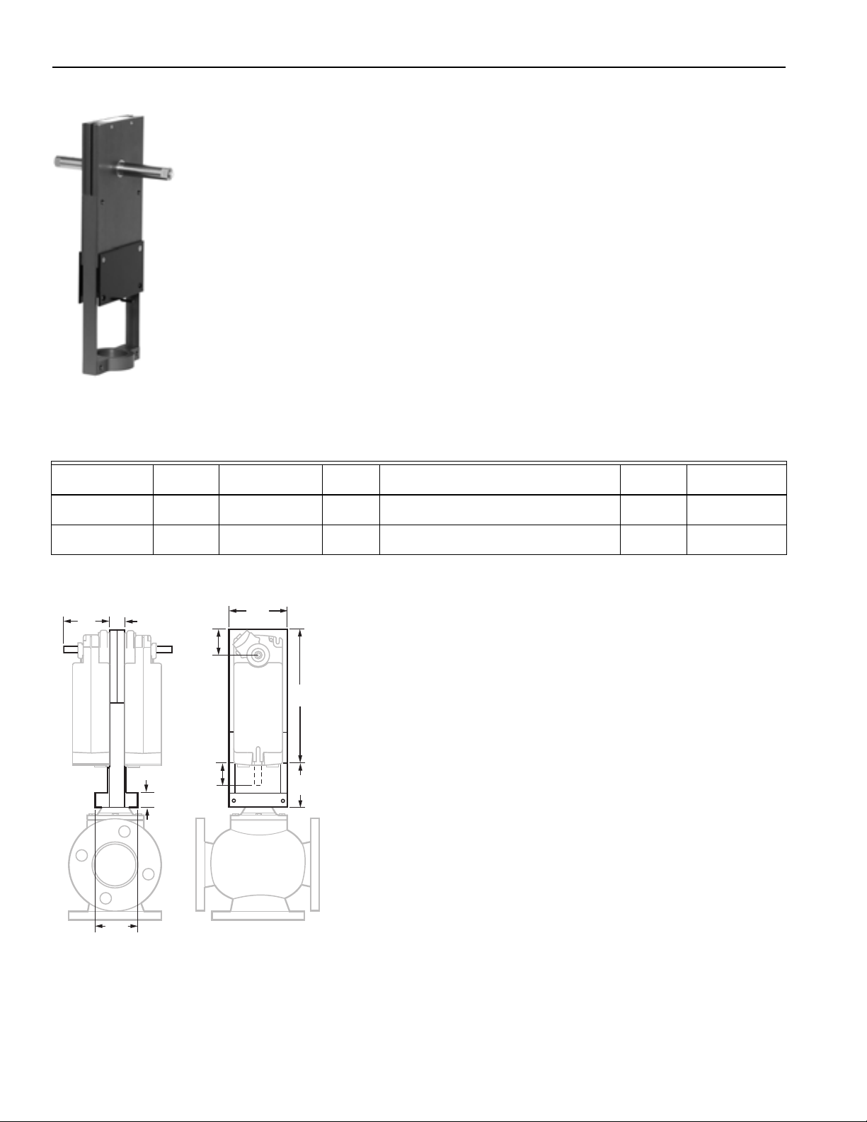
Q5022 Globe Valve Tandem DCA Linkage
The Q5022A,B Globe Valve Linkages connect one or two
Honeywell direct coupled rotary actuators (DCA) to a globe valve
for control of chilled water, hot water, or steam. The Q5022A,B
Linkages are compatible with 2 and 3-way globe valves up to 6 in.
(DN150) pipe size.
Q5022A is used to provide enhanced close-off ratings with
Honeywell globe valves up to 3 in. (1-3/8 in. diameter bonnet and
3/4 in. stem stroke).
Q5022B is used with Honeywell globe valves 4 to 6 in. (1-7/8 in. diameter
bonnet and 1-1/2 in. stem stroke).
• For use with 2-way and 3-way globe valves in
modulating or two-position service
• For use with 175 b.-in. (S20) spring return or 175 and 300 lb.-in.
(N20, N34) non-spring return DCAs
• Accepts single or dual matching actuators for higher close-off pressures
• Fail-safe operation with spring return DCAs, field selectable
normally open or normally closed for direct or reverse-acting valves
• Linkage threads onto valve stem
• Oilite™ self-lubricated actuator shaft bearing
• Anodized extruded aluminum housing
• Maintenance-free construction
• Precision roller-bearing rack construction to prevent premature
valve packing wear and leakage
• Flexible actuator mounting orientation
Linkage Type: Valve
Mounting: Linkage mounts directly to the valve bonnet; actuator(s)
mount on linkage
Used with Actuator: Direct Coupled Actuator
Stem Force Rating: 1117 lbf max (4969 N max)
Product Number
Q5022A1001/U 1 3/8 in. 1/4 -28UNF-2A 3/4 in. This linkage family is not compatible with the
Q5022B1009/U 1 7/8 in. 7/16 -20UNF-2A 1 1/2 in. This linkage family is not compatible with the
Bonnet
Size (in.) Shaft Dimensions Stroke Comments Includes Used With
43196000 high temperature kits
43196000 high temperature kits
Dimensions in inches (millimeters)
Anti-spin
function
Anti-spin
function
VGF under 4 in.;
V5013; V5011
VGF over 3 in.;
V5013; V5011
444 customer.honeywell.com 70-6910
Page 2
Damper and Valve Linkages
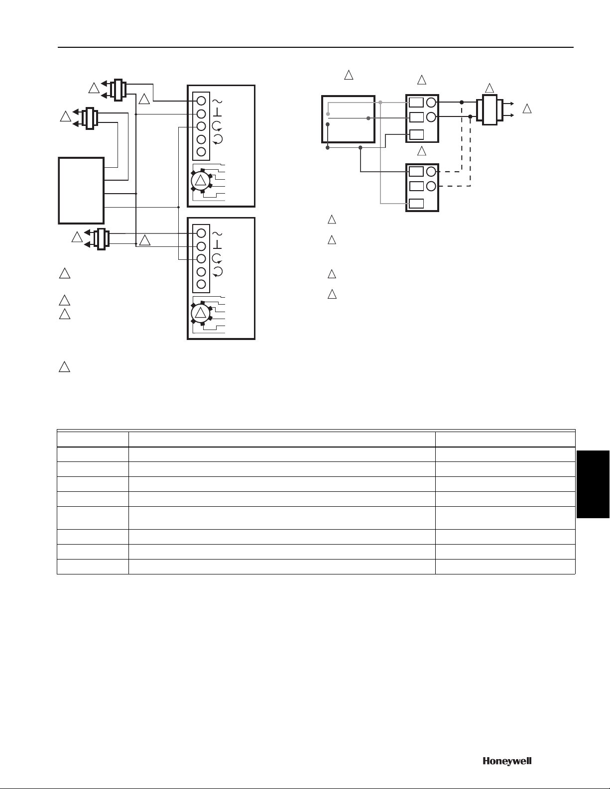
ACTUATOR
0/2 TO 10 VDC
PROPORTIONING
CONTROLLER
1
2
3
2
LINE VOLTAGE POWER SUPPLY.
PROVIDE DISCONNECT MEANS AND
OVERLOAD PROTECTION AS REQUIRED.
24 VDC SUPPLY ACCEPTABLE.
SET SWITCH TO MODULATING. ONE
OF THE ACTUATORS MUST BE SET
FOR REVERSE RESPONSE OVER THE
SAME INPUT SIGNAL SPAN. WIRE USING
SHIELDED CABLE WHEN USING 0-10 OR
10-0V SIGNAL SPAN GROUND SHIELD AT
CONTROLLER ONLY.
V
OR +
OR N/A
FEEDBACK
5
4
3
1
2
M27710
2-10 VDC
10-2 VDC
0-10 VDC
10-0 VDC
Fltg, fwd
Fltg, rev
3
ACTUATOR
V
OR +
OR N/A
FEEDBACK
5
4
3
1
2
2-10 VDC
10-2 VDC
0-10 VDC
10-0 VDC
Fltg, fwd
Fltg, rev
3
24 VAC
1
24 VAC
1
2
24 VAC
1
HOT
COM
–
+
4
ENSURE PROPER GROUNDING OF ACTUATOR CASE.
DO NOT GROUND SIGNAL COMMON.
M27648
W
B
R
3
4
4
2
1
3
3
1
1
4
4
24 Vac
2
2
1
1
L1
L2
MN6134
TYPICAL SPDT
CONTROLLER
MN6134
POWER SUPPLY PROVIDES OVERLOAD PROTECTION AND DISCONNECT
MEANS.
ALLOW UP TO 0.5 AMPS FOR EACH DEVICE. ACTUATORS AND
CONTROLLER CAN SHARE SAME TRANSFORMER, PROVIDED THAT THE
VA RATING OF THE TRANSFORMER IS NOT EXCEEDED AND PROPER
PHASING IS OBSERVED. DO NOT MIX A.C. AND D.C. POWER SOURCES.
CONTROLLER CAN BE LOW VOLTAGE SPDT SERIES 20 “ON-OFF” OR
SP3T SERIES 60 “FLOATING” (TRI-STATE) TYPE.
MULTIPLE ACTUATORS CONTROLLED BY A COMMON CONTROLLER IN
PARALLEL MUST BE WIRED SO THAT THEY ALL ROTATE IN THE SAME
DIRECTION.
1
2
3
4
Wiring and configuring modulating tandem actuators
with Q5022 linkages
Wiring of tandem floating actuators with Q5022 linkages
Commercial
Damper and Valve Linkage Accessories
Linkage Type: Damper
Product Number Description Used With
102546/U Ball Joint, 5/16 in. Damper Linkages
104643A/U Adapter for driving 2 dampers from 1 crank arm Kit Mounted Motors; Modutrol IV Motors
26025F/U Damper Arm, 3/8 in. shaft —
26026B/U Damper Arm, 1/2 in. shaft, 3 in. long —
32004629-001/U Bonnet adapter kit to adapt Seimens (Landis/Power) Flowrite 599 1/2 inch to 3 inch globe
valves with Q5020A or Q5009B
32004629-002/U Bonnet Adapter Kit, Johnson Controls 1/2 to 3/4 in., Q5020 Johnson valves; Q5020
32004629-003/U Bonnet Adapter Kit, Johnson Controls 1 to 2 in., Q5020 Johnson valves; Q5020
32004629-004/U Bonnet Adapter Kit, Siebe 1/2 to 2 in., Q5020 Siebe valves; Q5020
Components
Siemens valves
70-6910 445
 Loading...