

Page 1

Applicator Interface Board
For PX940
Installation Instructions
50158270-001 Rev B
03/20
Page 2
Introduction
This guide describes the Applicator Interface kit for PX940 Industrial Series
printers.
Description
The installation instructions describe how to physically install and configure
the applicator board in the printer.
Printer Firmware
The printer must be fitted with Honeywell Fingerprint v8.60 (or later).
Installation Kit
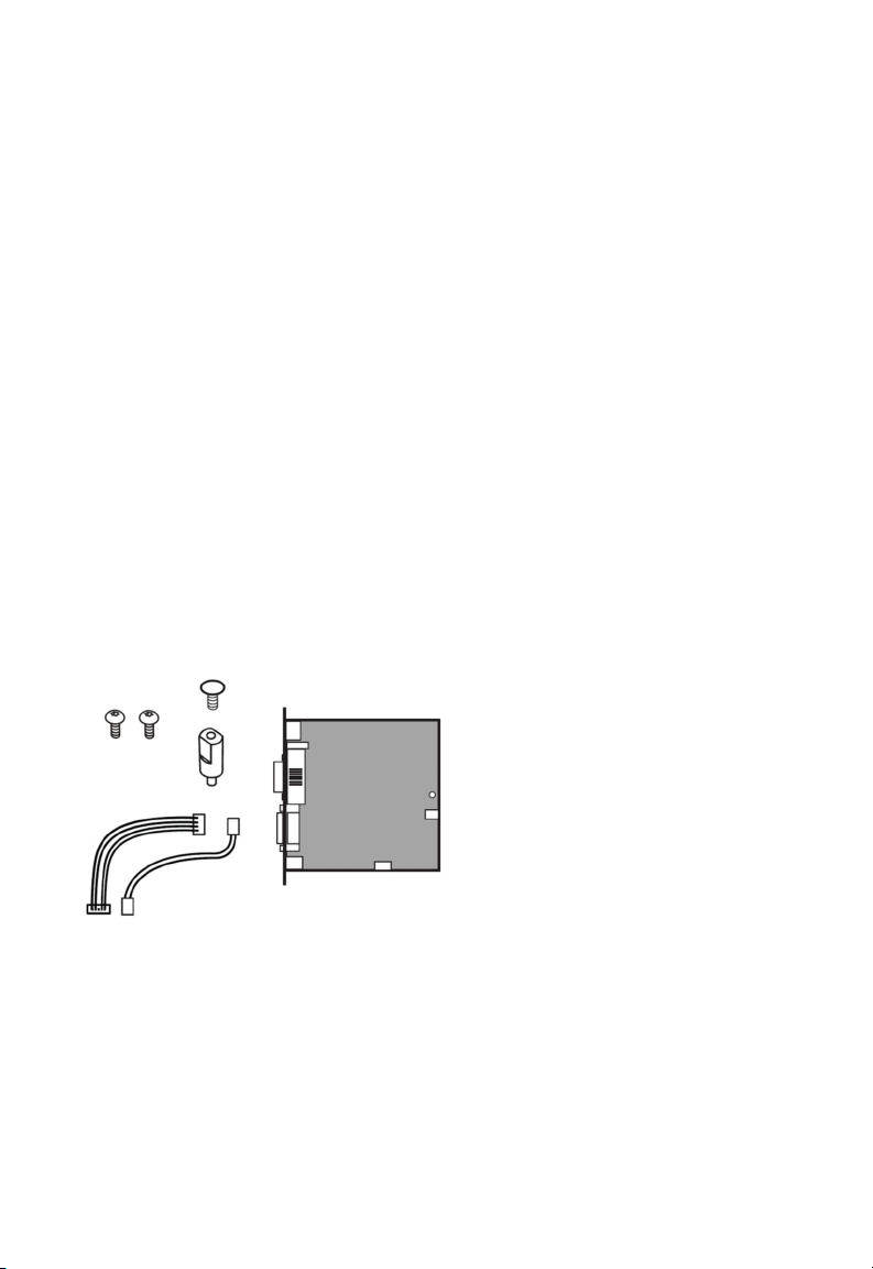
The Applicator Interface Board installation kit includes:
• One Applicator Interface Board
• One power cable
• One USB cable
• One spacer screw
• One 3X8mm Torx screw
• Two 4X8mm Torx screws
The only tools required for installation are the #T10 and #T20 Torx
screwdrivers.
PX940 Applicator Interface Installation Instructions 1
Page 3
Installing the Applicator Interface Board
Warning: The installation described in this section must only be
performed by an authorized service technician.
Honeywell assumes no responsibility for personal injury
or damage to the equipment if the installation is
performed by an unauthorized person.
Caution: Follow standard ESD guidelines to avoid damaging the
equipment.
Follow ESD
Procedures
Caution: Before you begin, turn off the printer and disconnect the
power cord and communication cables.
Follow the procedure to physically install Applicator Interface Board in the
PX940 printer.
1. Turn off the printer and disconnect the power cord.
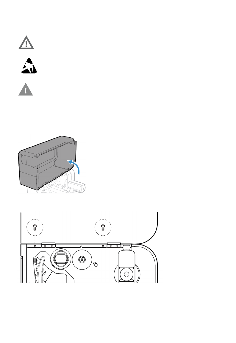
2. Open the media cover.
3. Use the T20 screwdriver to remove the two screws securing the electronics
cover to the inside of the printer base.
4. Close the media cover.
5. Remove the two screws located on the outside of the electronics cover.
2 PX940 Applicator Interface Installation Instructions
Page 4
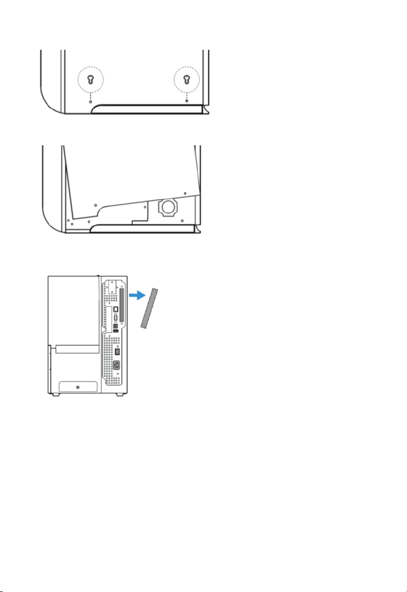
6. Remove the electronics cover.
7. Remove the two screws on the back of the printer securing the cover plate
and remove the cover plate.
8. Use the T10 screwdriver to remove the screw located on the top of the
printer main board and replace with spacer screw.
PX940 Applicator Interface Installation Instructions 3
Page 5
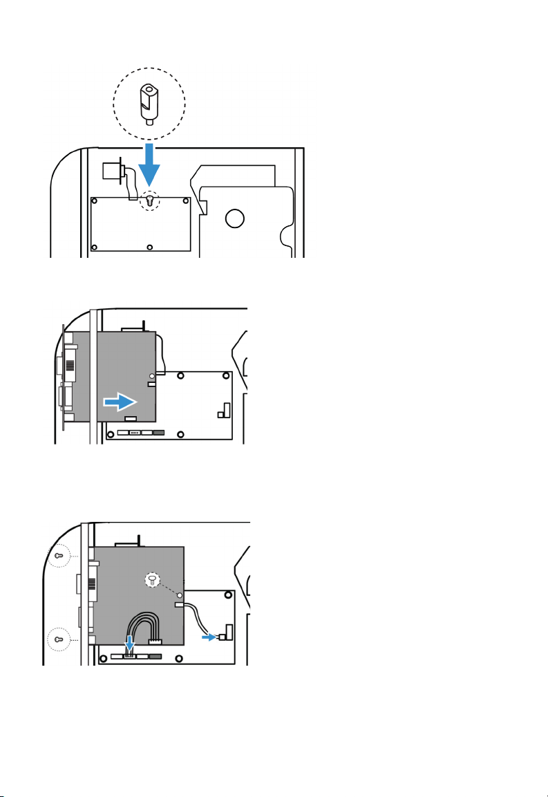
9. Insert the Applicator Interface Board into the printer and secure the board
assembly to the printer with two torx screws.
10. Secure the interface board assembly to the spacer screw with a Torx screw.
11. Insert the USB cable and power cable into the J37 and J33 connectors on
the printer main board. Then insert the other ends into the J1 and J2
connectors on the Applicator Interface Board.
12. Put the electronics cover back on and secure it with the 4 screws.
4 PX940 Applicator Interface Installation Instructions
Page 6
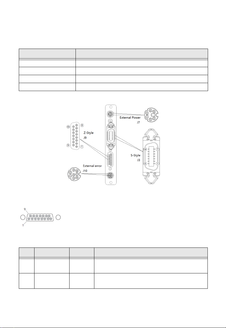
Interfacing
This option board contains 4 connectors for a Z-Style Port, a S-Style Port, an
External Power Port, and an External Error Port.
Port Description
Z-Style A D-Sub 15Pin receptacle connector.
S-Style A D Shaped SCSI 14Pin connector.
External Power A Mini-DIN 6Pin receptacle connector.
External Error A Mini-DIN 8Pin receptacle connector.
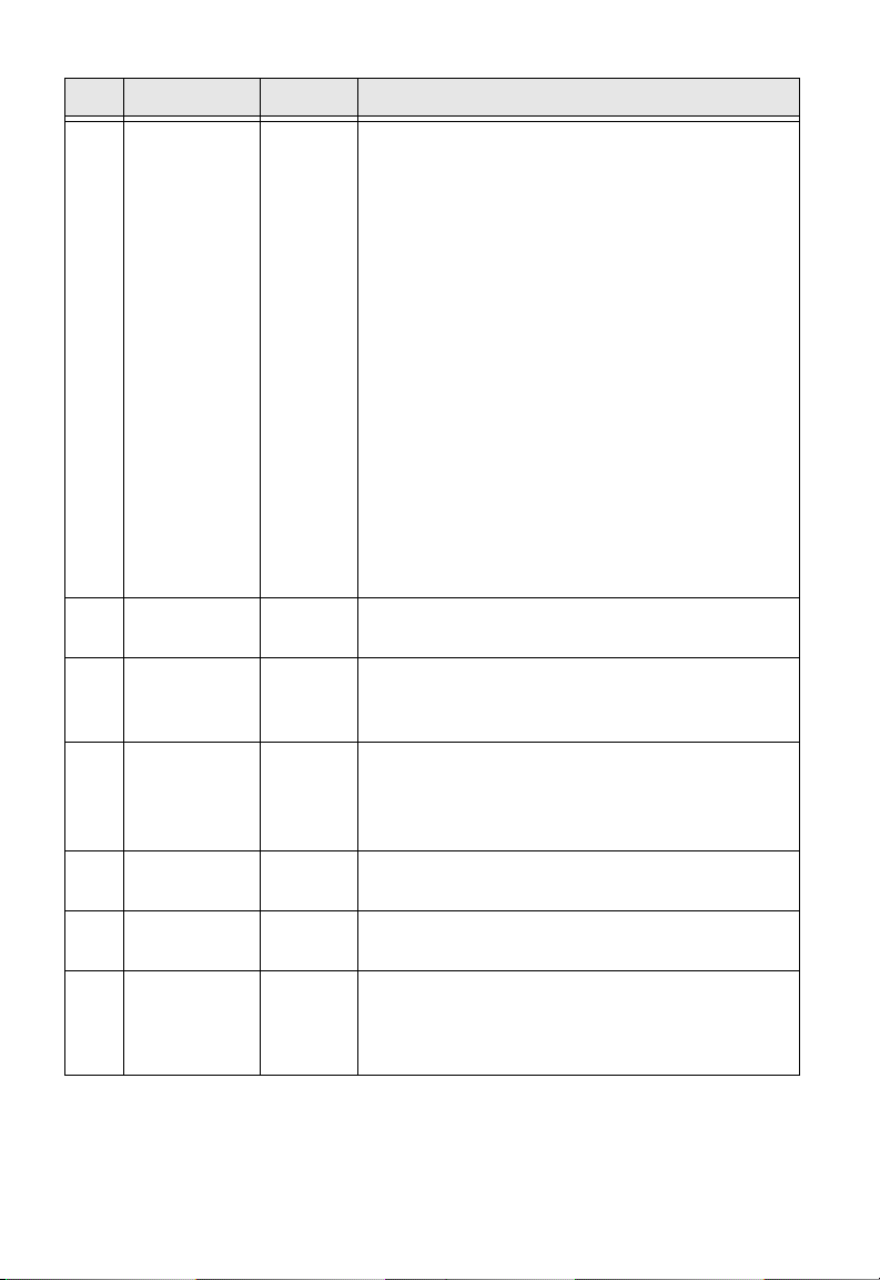
Z-Style Port
Z-Style Port Pinouts
Pin Signal Type Description
1Signal
groud
2 +5VDC Power Voltage supply for external sensors.
PX940 Applicator Interface Installation Instructions 5
Ground configurable for internal or external source
Configurable for internal or external source.
Page 7
Pin Signal Type Description
3 Start print Input Pulse Mode - prints one and only one label
whenever this pin is pulled to ground. Signal
must be de-asserted and reasserted to print
another label.
• Printing starts on HIGH to LOW transition if
format is ready.
• De-assert this signal to HIGH to inhibit
printing.
Level Mode - prints labels continuously when
this pin is pulled to ground. Printing is
disabled when signal is de-asserted. If a label
is printing when de-asserted, printing stops
after the label is complete.
• Assert LOW to start printing if format is
ready.
• De-assert HIGH when current label has
finished printing. Remains de-asserted
while waiting for the next label to be ready to
print.
4 Feed Input Assert LOW to feed label stock. De-assert
HIGH to stop feeding labels.
5 Pause Input Assert LOW for 200ms and then de-assert
HIGH to toggle between pause and un-pause
states.
6 Reprint Input Enables Reprint mode via software. When
this mode in enabled, assert LOW to reprint
last label. This input is ignored when reprint
mode is disabled.
7 +24VDC Output Power for external devices: +24VDC (±10%)
@ 2A.
8Power
Ground +24VDC return.
ground
9 Ribbon/
Media low
Output
Goes LOW when the ribbon/media roll
diameter drops below a predefined level,
otherwise Goes HIGH.
Media low is supported only by I-Style.
6 PX940 Applicator Interface Installation Instructions
Page 8
Pin Signal Type Description
10 Service
required
Output Goes LOW during every status that keeps the
printer from printing:
• Printhead lifted
•Ribbon out
•Media out
• General print engine fault
• Front arm lifted
• Verifier calibration required
• Verifier calibration expired
• Exceed maximum barcodes
• Verifier hardware error
• Verifier failure action prompt
11 End print Output Drives an applicator or other external device
requiring synchronization with the print
cycle. Choose between five types of output
signals:
• Mode 0: Applicator port is OFF.
• Mode 1: Asserted LOW only when media is
moving, otherwise de-asserted HIGH.
• Mode 2: Asserted HIGH only when media is
moving, otherwise de-asserted LOW.
• Mode3 (Default): Asserted LOW for 20ms
when label has finished printing and
positioned. Not asserted during continuous
printing.
• Mode 4: Asserted HIGH for 20 ms when label
has finished printing and positioned. Not
asserted during continuous printing.
12 Media out Output Goes LOW when the printer is out of media.
13 Ribbon out Output Goes LOW when the printer is out of ribbon.
14 Data ready Output Goes LOW when ready to print. De-asserted
HIGH when printing stops after the current
label.
15 Verification
failed
Output
Goes LOW when the printer encounters
Verification failed error.
Goes HIGH when the error is cleared.
PX940 Applicator Interface Installation Instructions 7
Page 9

S-Style Port
S-Style Port Pinouts
Pin Signal Type Description
1 Media out Output Goes LOW when the printer is out of media.
2Signal
ground
3 Ribbon out Output
4 Error Output Goes LOW during every status that keeps the
Ground Configurable for internal or external source.
Goes LOW when the printer is out of ribbon.
printer from printing:
• Printhead lifted
• Ribbon out
•Media out
• General print engine fault
•Front arm lifted
• Verifier calibration required
• Verifier calibration expired
• Exceed maximum barcodes
• Verifier hardware error
• Verifier failure action prompt
8 PX940 Applicator Interface Installation Instructions
Page 10

Pin Signal Type Description
5 Start print Input
Pulse mode - prints one and only one label
whenever this pin is pulled to ground. Signal
must be de-asserted and re-asserted to print
another label.
• Printing starts on HIGH to LOW transition if
format is ready.
• De-assert this signal to HIGH to inhibit
printing.
Level mode - prints labels continuously
when this pin is pulled to ground. Printing is
disabled when signal is de-asserted. If a label
is printing when de-asserted, printing stops
after that label is complete.
• Assert LOW to start printing if format is
ready.
• De-asserted HIGH when current label
has finished printing. Remains
de-asserted while waiting for next label
to be ready to print.
6 End print Output Drives an applicator or other external device
requiring synchronization with the print
cycle. Choose between four types of output
signals:
• Type 1 (Default): Asserted LOW for 20ms
when label has finished printing and
positioned. Not asserted during continuous
printing.
• Type 2: Asserted HIGH for 20ms when label
has finished printing and positioned. Not
asserted during continuous printing.
• Type 3: Asserted LOW only when media is
moving, otherwise de-asserted HIGH.
• Type 4: Asserted HIGH only when media is
moving, otherwise de-asserted LOW.
7 Reprint Input Enables Reprint mode via software. When
this mode in enabled, assert LOW to reprint
last label. This input is ignored when Reprint
mode is disabled.
8 Reserved
PX940 Applicator Interface Installation Instructions 9
Page 11

Pin Signal Type Description
9 Reserved
10 Ribbon/
Media low
11 Verification
failed
12 +24VDC Output Power for external devices: +24VDC (±10%)
13 +5VDC Power Voltage supply for external sensors.
14 Power
ground
Output Goes LOW when the ribbon/media roll
diameter drops below a predefined level,
otherwise Goes HIGH.
Media low is supported only by I-Style.
Output
Ground +24VDC return.
Goes LOW when the printer encounters
Verification failed error.
Goes HIGH when the error is cleared.
@2A.
Configurable for internal or external source.
External Power Port
External Power Port Pinouts
Pin Signal Type Description
1 +5VDC Input +5VDc input for distribution through Applicator
Port connector (Z-Style pin 2, S-Style pin 13)
2Signal
ground
3 +24VDC Input
4Power
ground
5 +24VDC Input
10 PX940 Applicator Interface Installation Instructions
Input Signal return for +5VDC supply (Z-Style pin 1,
S-Style pin 2)
+24VDC input for distribution through Applicator
Port connector (Z-Style pin 7, S-Style pin 12)
Input
Power return for input (Z-Style pin 8, S-Style pin 2)
+24VDC input for distribution through Applicator
Port connector (Z-Style pin 7, S-Style pin 12)
Page 12

Pin Signal Type Description
6Power
ground
Input
Power return for input (Z-Style pin 8, S-Style pin 2)
External Error Port
PX940 Applicator Interface Installation Instructions 11
Page 13

External Error Port Pinouts
Pin Signal Type Description
1 AppErr_1 Input
Applicator error #1,
applicator device to signal error for
printer to receive status of applicator.
2 AppErr_2 Input
Applicator error #2,
applicator device to signal error for
printer to receive status of applicator.
3 AppErr_3 Input
Applicator error #3,
applicator device to signal error for
printer to receive status of applicator.
4 RtW_in_Ext Input
5+5VDC Output
6 RtW_Out Output
7 Ground Ground
8 Ground Ground
External input signal from the applicator to
the printer, for the printer to switch to the
same state with the applicator, and behave in
sync as part of the entire system.
Available for applicator.
External output signal indicating the printer
is Ready to Work.
Signal may be asserted LOW when there are
no active events in the System Health
Monitor (SHM), when the printer motor is
idle, or both.
Available for applicator.
Available for applicator.
reserved for external
reserved for external
reserved for external
Applicator Signals
The diagrams below show how applicator signals function in each applicator
mode during the stages of printing labels.
12 PX940 Applicator Interface Installation Instructions
Page 14

End Print Mode 1/Type 3
PX940 Applicator Interface Installation Instructions 13
Page 15

End Print Mode 2/Type 4
End Print Mode 3/ Type 1
End Print Mode 4/ Type 2
Configuring Applicator Port Settings
The applicator interface supports three different applicator modes:
• Z-Style. Choose this mode for a Zebra-type applicator.
• S-Style. Choose this mode for a Sato-type applicator.
• I-Style. This mode combines Z-Style or S-Style settings with the ability to
trigger external I/O systems via the External Error port.
14 PX940 Applicator Interface Installation Instructions
Page 16

You can configure applicator port settings from the web browser interface or in
Setup Mode.
Web Browser Interface
1. From the menu, click System Settings > Manage I/O. The configuration
screen appears.
2. Chose Enable from the drop down list for the Applicator.
3. From the menu, click Configure > Printing > Applicator.
4. Choose desired settings from the drop down lists.
Setting Description
Style I-Style, Z-Style, S-Style
Startprint Level or Pulse
Endprint Mode 0, Mode 1/Type3, Mode2/Type4, Mode3/Type 1,
Mode 4/Type 2
Ribbon/Media Low Enables/disables the printer low ribbon alert message.
Enables/disables the printer low media alert message.
Reprint Enables/disables reprinting the last label sent to the
printer (by using the Reprint signal)
Error on Pause Enable this setting to set the ”Service Required” signal
when the printer is paused. This setting supported by
Z-Style only.
Error Port Enables/disables the printer external error port.
RTW Configures the Ready-to-Work output signal
(RTWOUTEXT). Choose from:
• Mode 1 - Signal is asserted low when no events are
active in the System Health Monitor (SHM).
• Mode 2 - Signal is asserted low when the printer motor
is idle.
• Mode 3 - Signal is asserted low when the printer motor
is idle and no events are active in the SHM.
DC 5V Configures the printer to use either its internal power
supply or an external supply (connected to the External
Power port) to provide +5VDC to the Z-Style and S-Style
ports.
PX940 Applicator Interface Installation Instructions 15
Page 17

Setting Description
DC 24V Configures the printer to use either its internal power
supply or an external supply (connected to the External
Power port) to provide +24VDC to the Z-Style and
S-Style ports.
5. Click Save. The settings are saved.
Setup Mode
Use the printer touch screen to view and change settings.
1. Press Menu > Settings > System Settings > Manage I/O.
2. Choose Enable from the drop-down list for the applicator.
3. From the menu, select Menu > Settings > Printing > Applicator.
About Applicator Input Signals
This section describes the INPUT signals.
Note: All IN signals are asserted low and de-asserted high.
Signal Description
Startprint
Feed
Pause
Reprint
Apperr1
Apperr2
Apperr3
RTWINEXT
Starts a print job. Choose either Level or Pulse.
• Level: The printer starts printing labels when the
startprint signal is asserted and continues printing
until the signal is de-asserted.
• Pulse: The printer prints one label when the startprint
signal is asserted. The startprint signal must be
de-asserted and then asserted to print the next label.
Feeds a single label. Not supported by S-Style.
Toggles between Pause mode and printing. Not
supported by S-Style.
Reprints the last valid label.
Applicator error 1.
Applicator error 2.
Applicator error 3.
External input signal, which you can use to monitor the
operational status of the entire system.
16 PX940 Applicator Interface Installation Instructions
Page 18

About Applicator OUT Signals
This section describes the Applicator OUT signals.
Note: Unless described otherwise, all OUT signals are asserted low and
de-asserted high.
Signal Description
Data Ready Asserted when the printer is ready to receive a startprint
signal and execute the current print job. De-asserted
when the print cycle ends. Not supported by S-Style.
Endprint Asserted during or after a print cycle. The endprint signal
also behaves differently depending on the applicator
port endprint mode. When the startprint signal is
received, the endprint signal may or may not be
asserted.
There are five options to choose from:
• Mode 0: Endprint signal is never asserted.
• Mode 1 (Z-Style)/Type 3 (S-Style): Asserted low during
print/feed cycle.
• Mode 2 (Z-Style)/Type 4 (S-Style): Asserted high during
print/feed cycle.
• Mode 3 (Z-Style)/Type 1 (S-Style): Asserted low for at
least 20 ms after print/feed cycle end.
• Mode 4 (Z-Style)/Type 2 (S-Style): Asserted high for at
least 20 ms after print/feed cycle end.
Media out Asserted when the printer is out of media. Activates an
SHM PaperOut event in the System Health Monitor
(SHM). De-asserted when the same event is deactivated.
Ribbon/Media
low
Ribbon out Asserted when the printer is out of ribbon. Activates an
Asserted when the ribbon/media roll diameter drops
below a predefined level. De-asserted while the roll
diameter remains above the predefined level.
Media low is supported only by I-Style.
SHM RibbonOut event in the System Health Monitor
(SHM). De-asserted when the same event is deactivated.
PX940 Applicator Interface Installation Instructions 17
Page 19

Signal Description
RTWOUTEXT External output signal.
Behavior depends on the current setup. Signal may be
asserted when there are no active events in the System
Health Monitor (SHM), when the printer motor is idle, or
both.
This signal is inactive when the Error Port option is
disabled.
SERVICEREQ
(Service Required)
Asserted low when an event in the System Health
Monitor (SHM) is activated. De-asserted when no events
are active in the SHM.
A “service required” event is also activated when the
Error Port is enabled and any applicator errors is
detected. This signal is also asserted when the Error on
Pause option is enabled.
Programming Applications for the printer
The printer includes Honeywell Fingerprint, a programming language that
resides on the printer. Fingerprint is an easy-to-use programming tool for label
formatting and printer customization.
Fingerprint also includes a slave protocol, Honeywell Direct Protocol, which
allows layouts and variable data to be downloaded from a host and combined
into labels, tickets, and tags with a minimum of programming. Honeywell Direct
Protocol also includes a versatile error handler and a flexible counter function.
Fingerprint Commands for the printer
The ON PORTIN, PORTIN, PORTOUT, and ON PORTOUT Fingerprint commands
support applicator functionality for the printer. These commands are functional
when the printer applicator port status is enabled.
This section includes basic information for each of these commands. For more
information, see the Fingerprint Command reference manual.
ON PORTIN
This command allows a Fingerprint application to detect in signals. If a particular in signal is asserted, the application moves to the subroutine responsible for
carrying out tasks related to that in signal. One command is available for detection of each of the 8 in signals.
Note: This command is not supported by Honeywell Direct Protocol.
Example:
18 PX940 Applicator Interface Installation Instructions
Page 20

• ON PORTIN.STARTPRINT GOSUB nnn
PORTIN
This command is a version of the PORTIN(PORT) command and checks the
current state of a specified signal. This command returns -1 if the signal is
asserted, or 0 if the signal is de-asserted.
Note: This command is supported by Fingerprint and Direct Protocol.
Examples:
• PORTIN.STARTPRINT
or
• PORTIN.RIBBONLOW
PORTOUT
Supports manually modifying the dataready signal. PORTOUT is not allowed
when the applicator port style is set to S-Style.
Note: This command is not supported by Direct Protocol.
Example
• PORTOUT.DATAREADY ON
• PORTOUT DATAREADY OFF
where on asserts the dataready signal low and off de-asserts the dataready
signal high.
ON PORTOUT
This command allows a Fingerprint application to detect when out signals have
been reset to default values. The command moves to a specified subroutine
whenever the applicator port status is enabled, and whenever the applicator
port style is changed.
Example:
• ON PORTOUT.RESET GOSUB nnn
Using External Applicator Signals
The printer responds to external applicator port signals differently, depending
on whether your application is using Fingerprint or Honeywell Direct Protocol.
Fingerprint and Applicator Signals
When you use Fingerprint, all in signals and the Data-ready out signal are
handled by Fingerprint. Other out signals are handled by firmware.
PX940 Applicator Interface Installation Instructions 19
Page 21

Feed
When the Feed in signal is received, the application moves to a specified subroutine that feeds labels until the Feed in signal is de-asserted.
Example
• 10 ON PORTIN.FEED GOSUB 200
...
200 FORMFEED
210 RETURN
Pause
When the Pause in signal is received, the application moves to a specified subroutine that finishes the current print job and then places the printer in pause
mode.
Example
• 10 ON PORTIN.PAUSE GOSUB 90
...
90 pause printer
Startprint
When the Startprint signal is received, the application moves to a specified
subroutine that starts the print job. The Startprint signal must be preceded by
the dataready signal as seen in this example.
Example
• 10 PORTOUT.DATAREADY on
20 ON PORTIN.STARTPRINT GOSUB 60
...
60 my print routine
70 PRINTFEED
80 RETURN
Reprint
When the Reprint signal is received, the application moves to a specified subroutine that reprints the last valid label.
20 PX940 Applicator Interface Installation Instructions
Page 22

Example:
•...
100 ON PORTIN.REPRINT GOSUB 150
...
150 PRINTFEED -1,1
160 RETURN
Printfeed
The dataready signal must be set manually by the Fingerprint application
before a printfeed is issued when using with an applicator.
Handling External Applicator Errors
When an error signal (apperr1, apperr2, or apperr3) is received, the application
moves to a specified subroutine that takes action based on error severity.
Example
•...
60 ON PORTIN.APPERR1 GOSUB 100
...
100 perform error handling
110 RETURN
Handling Internal System Errors
For internal system errors, the system error signal status can be read at any
time within the application so appropriate measures can be taken. When any of
these errors occur, the appropriate out signal (including the error) is asserted:
• Printhead lifted
• Ribbon out
• Media out
• General print engine fault
•Front arm lifted
• Verifier calibration required
• Verifier calibration expired
• Exceed maximum barcodes
• Verifier hardware error
• Verifier failure action prompt
Example
• 10 IF PORTIN.RIBBONLOW GOTO 200
...
PX940 Applicator Interface Installation Instructions 21
Page 23

200 perform error handling
210 RETURN
Resetting Out Signals
Out signals are reset to their default values when certain options are changed
by using the SETUP menu. When the reset is detected, the application moves to
a specified subroutine and performs the tasks necessary to reinitialize the print
engine.
Example
• 10 ON PORTOUT.RESET GOSUB 150
...
150 perform initialization
160 RETURN
Direct Protocol and Applicator Signals
In Direct Protocol, all in and out signals are handled by the Direct Protocol firmware.
Feed
There are two ways to trigger blank label feeding:
• by manually pressing Feed on the printer front panel. The printer feeds a
single blank label.
• by using the Feed in signal. When this signal is detected, the printer feeds
blank labels as long as internal applicator flag indicates that the Feed
signal is asserted.
Pause
The applicator can toggle the current pause state by using the pause in signal
to simulate pressing Pause on the printer front panel. When the printer is in
pause state, you can press Setup on the printer front panel and place the print
engine in Setup Mode for manual configuration.
Startprint
When the printfeed command is executed, the print process sets the dataready
signal and then waits for the startprint signal to be detected before proceeding
with the print job.
The print process will not set another dataready signal until the current print
job de-asserts the previous dataready signal. This prevents the printer from
printing a new label before the previous label is completed.
22 PX940 Applicator Interface Installation Instructions
Page 24

Reprint
This signal works much the same way as startprint. The reprint signal is
detected under two conditions:
• when the printer is idle.
• when the printer is waiting for a startprint signal during the execution of a
printfeed command.
The printer prints only one label at a time.
Handling External Applicator Errors
The external applicator error in signals (APPERR1, APPERR2, APPERR3,
RTWINEXT) should be asserted when external applicator errors occur. When
one of these signals is detected, an associated event is activated in the System
Health Monitor (SHM). When the issue causing the error has been resolved and
the error signals are de-asserted, the events are deactivated in the SHM.
Handling Internal System Errors
When a system error occurs that activates an event in the SHM, the “service
required” signal is asserted. The external RTW out signal can be de-asserted,
depending on the current print engine RTW setting.
When any of these errors occur, the appropriate out signal (including the error)
is asserted:
• Printhead lifted
• Ribbon out
• Media out
• General print engine fault
•Front arm lifted
• Verifier calibration required
• Verifier calibration expired
• Exceed maximum barcodes
• Verifier hardware error
• Verifier failure action prompt
PX940 Applicator Interface Installation Instructions 23
Page 25

Error Messages
Message:
Cause:
ERRNOAPP
Operation not allowed. Applicator Port disabled.
Application sent an applicator port command to the printer
and the applicator port is disabled.
Error Number:
Message:
Cause:
Error Number:
Message:
Cause:
Error Number:
Message:
Cause:
Result:
Error Number:
88
ERRAPP
Operation not allowed. Applicator Port enabled.
Application sent the Fingerprint command PORTOUT(PORT)
ON|OFF on a port used by the applicator port when the
applicator port is enabled.
89
ERRINPUTON
Operation not allowed in Direct Protocol.
Running the PORTOUT.DATAREADY ON|OFF or
PORTIN.<SIGNAL> GOSUB XXX commands when the printer
is using Direct Protocol.
90
EAPPERR1
Applicator Error 1.
AppErr1 in signal detected.
Activates event in System Health Monitor (SHM).
1340
EAPPERR2
Message:
Cause:
24 PX940 Applicator Interface Installation Instructions
Applicator Error 2.
AppErr2 in signal detected.
Page 26

Result:
Error Number:
Message:
Cause:
Result:
Error Number:
Message:
Cause:
Result:
Error Number:
Message:
Cause:
Activates event in System Health Monitor (SHM).
1341
EAPPERR3
Applicator Error 3.
AppErr3 in signal detected.
Activates event in System Health Monitor (SHM).
1342
ERTWINEXT
RTW Extenal Error.
RTWExternal in signal detected.
Activates event in System Health Monitor (SHM).
1343
ENODATAREADY
Dataready not enabled.
Application sent a PRINTFEED in Fingerprint when the
applicator port is enabled, the style is set to I-Style or Z-Style,
and the dataready signal is not enabled.
Result:
Error Number:
PX940 Applicator Interface Installation Instructions 25
Terminates the printfeed command without printing a label.
1344
Page 27

Display Messages
These messages appear in the printer display under certain conditions when a
PRINTFEED command is run.
Message:
Cause:
Message:
Cause:
APPLICATOR PORT: Wait for signal.
Running a PRINTFEED command blocks execution until a
startprint signal is received. The message appears when
execution has been blocked for a few seconds.
APPLICATOR PORT: Wait for reprint.
Running a PRINTFEED -1,1 command blocks execution until a
reprint signal is received. The message appears when execution
has been blocked for a few seconds.
26 PX940 Applicator Interface Installation Instructions
Page 28

Support
To search our knowledge base for a solution or to log into the Technical Support
portal and report a problem, go to www.hsmcontactsupport.com.
User Documentation
For the user guide and other documentation, go to www.honeywellaidc.com.
Limited Warranty
For warranty information, go to www.honeywellaidc.com and click Get
Resources > Product Warranty.
Patents
For patent information, see www.hsmpats.com.
Disclaimer
Honeywell International Inc. (“HII”) reserves the right to make changes in specifications and other information contained in this document without prior
notice, and the reader should in all cases consult HII to determine whether any
such changes have been made. The information in this publication does not
represent a commitment on the part of HII.
HII shall not be liable for technical or editorial errors or omissions contained
herein; nor for incidental or consequential damages resulting from the furnishing, performance, or use of this material. HII disclaims all responsibility for the
selection and use of software and/or hardware to achieve intended results.
This document contains proprietary information that is protected by copyright.
All rights are reserved. No part of this document may be photocopied, reproduced, or translated into another language without the prior written consent of
HII.
Copyright2009-2020 Honeywell International Inc. All rights reserved.
PX940 Applicator Interface Installation Instructions 27
 Loading...