

Page 1
USER GUIDE
Pro and SuperPro™ Series
User Guide for the
Pro and SuperPro
Home Network Distribution Panels
©
2001 FutureSmart Networks, Inc.
6583 Cottonwood St., Murray, UT 84107
Tel. 801-263-1300
Table of Contents
Overall Diagram of FutreSmart Pro/SuperPro Series…………………
Components of a Home Network System……………………………..
Pro/SuperPro series Panel………………………………………
Coax Module…………………………………………
Telephone Module…………………………………..
Expansion Bays……………………………………..
Cable and Wire………… ……………………………………
Multimedia Outlets…………………………………………..
System Options……………………………………..
Satellite Distribution………………………………
Data and Computer Networking……………….
Security System……………………………….
Whole House Sound………………………………..
Line Breakout Module (LBO-1)……………………
Multi Room Video…………………………………
Pro/SuperPro Series System Basic Functions and Description……..
Coax hub………………………………………………..
Patching video signals…………………………..
Changing To Cable or Antenna Signal…………..
Telephone Module……………………………………………
Patching phone signal………………………….
Testing phone signal……………………………..
Page 2
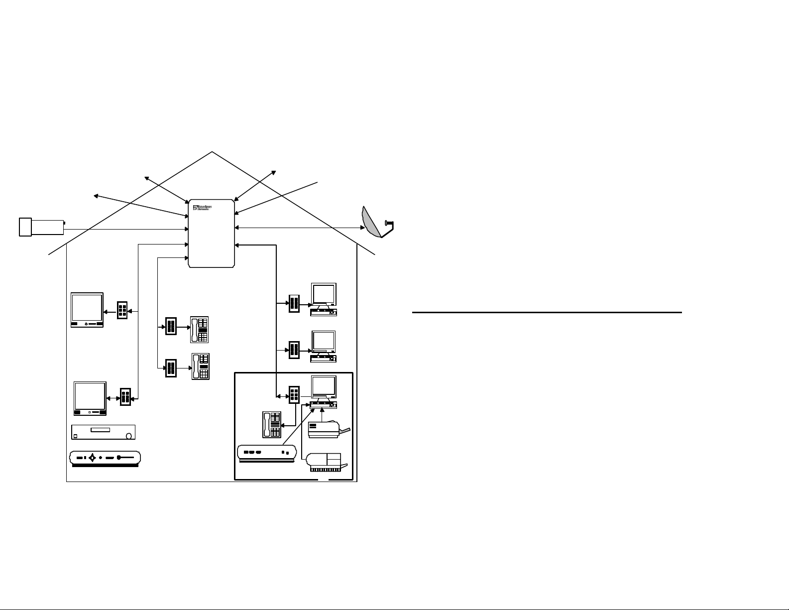
CABLE TV
PROVIDERS
CCTV Camera
Overall Diagram of FutureSmart
Pro/SuperPro series
TELEPHONE
SERVICES
PROVIDERS
Pro Panel
Televisions
Phones
Stereo & Surround
Sound
DVD/VCR Player
Satellite receiver
1
DIGITAL DTD
LINKS
Home Office
Modem (DSL/Cable)
ANTENNA
Computers
Laser printer
FAX
SATV dish
Congratulations! You have purchased a
FutureSmart Pro/SuperPro Series Home
Network for your home or office. This Home
Network will permit you to control which signals
go to which rooms. It will allow you to network
(connect together) your video products,
computers, telephones; and many other products
you now own, or may purchase in the coming
months and years. Contained in this Users
Guide is information about your Home Network,
its benefits and the ways in which you can
control, adjust or add to your Home Network.
Components of a Home Network System
Before we get started lets get acquainted with
the components of your Home Network System.
These are:
The FutureSmart Pro series system in made up
of four key parts that make the network integrate
seamless:
(1) Pro panels (the brain of the system)
(2) The Multimedia cable and wire
(3) The Multimedia outlets
(4) System Options (cameras, computers, etc.)
2
Page 3
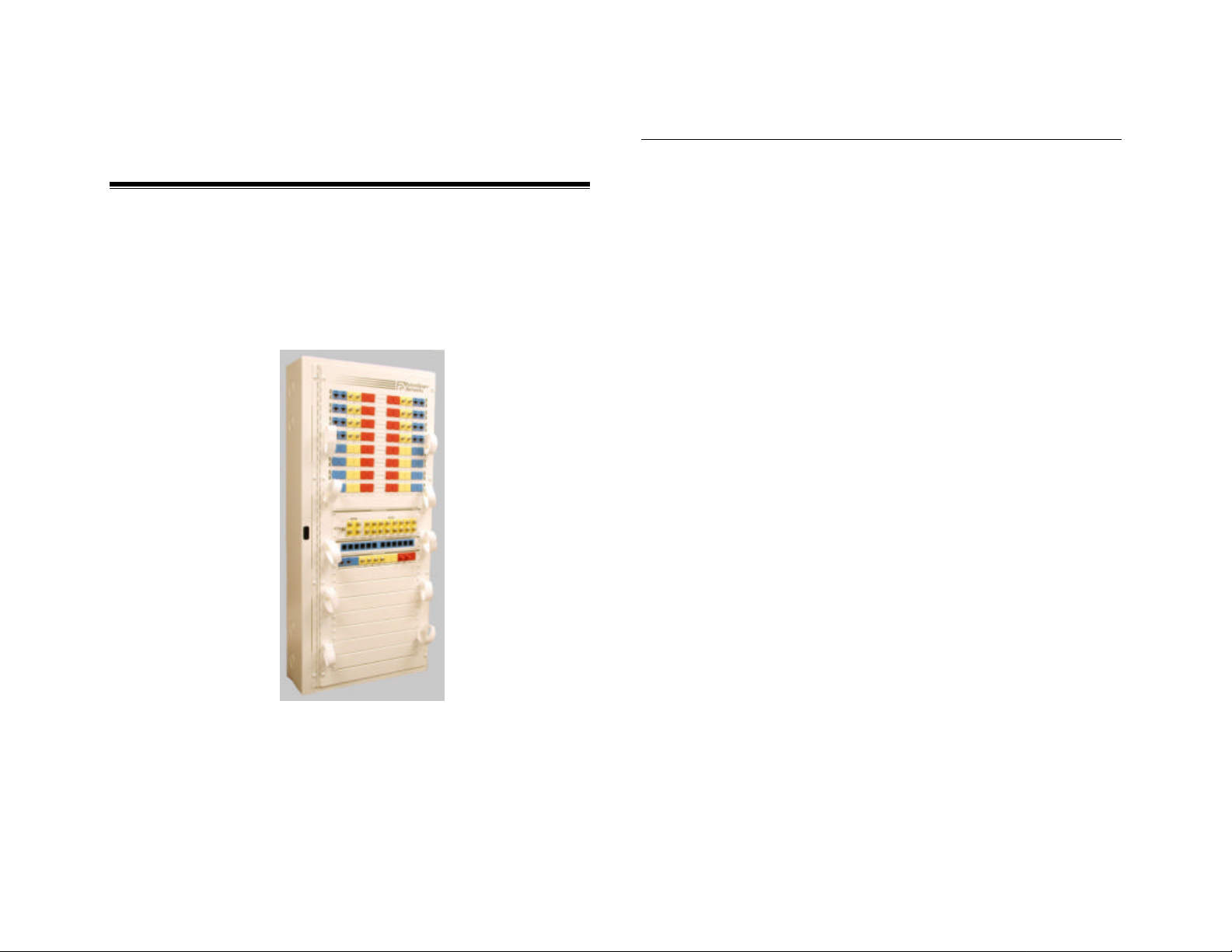
Pro/SuperPro panel
The Pro/SuperPro panel is the brain of the
FutureSmart home network system. All information
such as TV, phones, computer, Internet, security,
etc. coming into the home will go through this panel
and are distributed to individual rooms. This is also
where all of the information generated inside the
home will be either redistributed or sent back out to
the world.
These panels were designed for you, the
homeowner to make simple changes to your system,
such as
[1]
[2]
[3]
[4]
[5]
the sy stem will vary from home to home depending
activating
phone or/and
TV outlets in
your home, or
even
disconnecting
or moving the
signals around
in the home.
The design
also allows
your installer to
make quick
and easy
upgrades to
your system.
The features
that make up
on the services used. A standard Pro/SuperPro
includes the following features and functions.
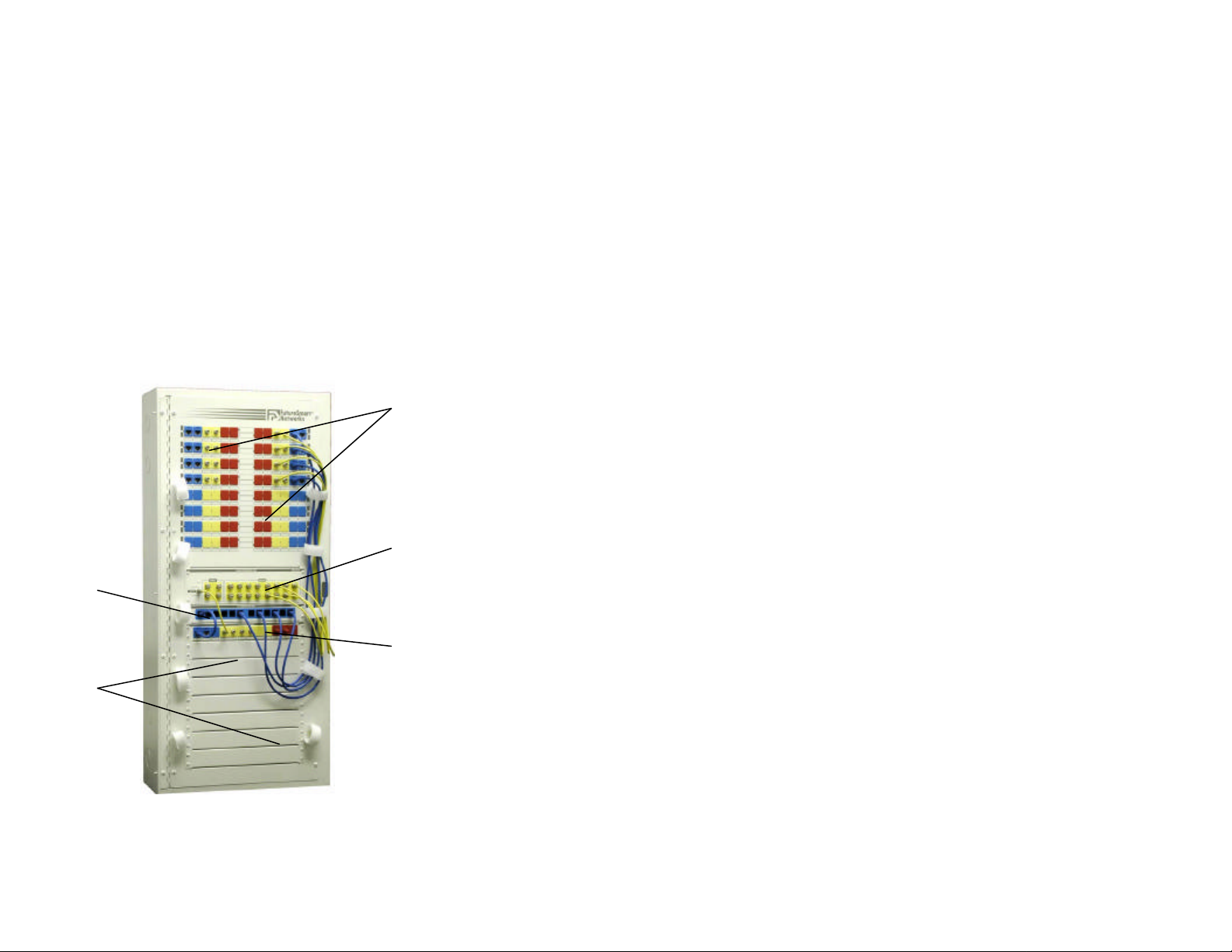
[1] The zone location is where all of your low
voltage outlets are connected to on the backside of
the panel. From the front side of the panel there will
be different types of patch cords coming from the
bottom of panel up to the zones that need to have
telephone, TV, and computer signals.
[2] The coax hub will send the video signals to 8,
12,or to 16 (depending on the model type) multi media outlets and/or TV outlets through out the
home such as antenna, cable TV, Satellite, DVD,
VCR player’s signals and any other types of video
signals.
[3] The telephone hub is a distribution point for up
to 4 incoming phone lines that will send phone
signals to 11 rooms that require phone service.
[4] The service input hub is where the outside
services connect to the panel. Services such as
phone lines, cable TV, antenna, and satellite signals
will be connected to the backside of the hub and
then patched to the corresponding distribution hubs.
[5] Expansion bay may have blank covers or you
may have Network Accessories installed. This is
Page 4

where optional hubs may be installed for computer
123
networking, video distribution, security , satellite TV, etc.
2.Multimedia cables and Wire
The extremely high volume of information in today’s
and tomorrow’s technology requires that the cables
and wires inside your walls that are connected to the
Pro panel be of high quality. There will be different
types and combinations of cables used with the
FutureSmart Pro panel. The black and pink cables
are known as “coaxial RG6 quad shield cable”.
This kind of cable is used to send TV video signal to
the outlets in the rooms and to send signals from the
room to the panel. The blue and yellow cables are
“Category 5e or 6 Category twisted pair
telephone
cables”. These
cables are
generally used for
phone, fax outlets
and to connecting
computers
together.
Together with
these single cables you may find a Multimedia
cable that is 2- Rg6 cables and 2-Category 5e or 6
cables that are bundled or jacketed together. Or the
same cable with the addition of an orange and gray
cable, which are fiber optics that in the future, will be
used to send all (video, computer, and phone) types
of signal at a very high speed and rate. All of these
cables are “Home Run” which means that from the
Pro panel each cables run out to one location and
one location only.
3. Multimedia Outlets
The Multi Media outlet or single phone and TV
outlets will be found in each room that a “Home run “
cable or wire is run to. They are installed at
convenient locations through out the home to access
the information coming into the Pro/SuperPro panel.
The Multimedia outlet you can access different
kinds of information at one outlet such as phone, TV,
and Internet service.
Optional outlets you may
have, contain a different
version of the Multimedia
outlet. These versions may
contain different qualities of
cables it may be as simply
as a single port plates with
just a phone or TV
connector or you could
have and combination of
the two types.
[1] Two RJ45 telecom ports (accept standard
telephone jacks inserts) Used for single or multiple
Page 5

line telephones or dedicated fax lines, dedicated
modem lines, and data.
To access multiple lines See LBO in System Option.
[2] Two ST fiber jacks (optional).
Used for hooking computer together for high speed
communication, phone lines, and TV video signals.
[3] Two RG6 coax TV jacks (“F” connectors)
Used for video (cable TV, antenna, satellite, cable
modem, and internal video).
4. System Options
System Option are options that are added to the
system for enhanced capabilities. System options
include whole house audio, satellite distribution,
home security system, and more. Your Pro series
panel may contain one or more options depending
on the services you will be utilizing in your home.
Satellite Distribution (HBDS- 4)
This Module will allow you to expand your standard
Digital Satellite system from two receivers to up to
four receivers. So that you can watch four different
chann
els at
four
locati
ons at
the
same
time.
Note: This hub will
only work with a
dual LnB satellite
system.
[1]OUTPUTSWarning Note:
ONLY hook these
lines up to a
satellite receiver, voltage on the line can cause
damage to TV’s or VCR’s.
[2] INPUTS- These ports connect the lines from a
Satellite Dish and split the voltage to four outputs.
Data and Computer Networks (HBEN-10/100)
One of the many benefits of a Home Network is
the ability to share information between all the
computers in the home or office. A Local Area
Network (LAN) or
computer network
requires 4
components. A
Network Interface
Card (NIC)
installed at each computer, an Ethernet, wiring and
networking software. Before purchasing the
components for your home network, you should
decide on the speed at which you would like to
operate your LAN. Current options are
10BaseT(10 Mbps) and 100BaseT (100Mbps).
1. Install the Network Interface Cards (NIC’s) into
Page 6

the computers which you want to be connected to
your LAN. Be sure to follow the NIC
manufacturers installation instructions.
2. Connect the power transformer to the rear of the
Ethernet hub.
3. Install the FutureSmart Ethernet hub into the
expansion bay of your Pro series panel by
removing a blank cover and placing the hub in the
open slot.
4. Use a patch cord to connect the NIC in the
computer to the data jack in your receptacle.
5. Connect the data cable from the desired room
into one of the 4 inputs on the front of the
Ethernet hub. Be sure to label the port so you
know where the cable originated from.
6. The Ethernet hub can be linked to another
Ethernet hub by patching from the I port to one of
the new Ethernet hub X ports..
7. Configure your LAN with the Network software
you have chosen. Be sure to follow the
instructions provided by the software
manufacturer.
Security System (HBSC)
FutureSmart offers a security system that mounts
directly into the expansion area of your Home
Network. The security system supports up to 32
zones and can be partitioned to function as 4
separate systems. FutureSmart offers a
accessories to customize your security system,
such as smoke
detectors, motion
detectors, glass break
detectors, window &
door contacts, sirens,
etc.
The sleek security keypad is easy to understand
and use. The large LCD display is easy to read.
Additionally, with the use of wireless motion
detectors and contacts, expansion of the security
system is simple.
Whole House House (HBAD- 8)
With the addition of a FutureSmart Audio hub, you
can enjoy music in any area of your home. The
Audio hub connects to your existing stereo
receiver that has a CD player, tape deck, DVD
player, etc. and distributes the sound to 8 stereo
locations. This hub contains the following:
[2]
[1]
Page 7

[1]SPEAKER INPUT- The hub receive right & left
speaker signals from a stereo receiver.
[2] SPEAKER OUTPUTS- The hub distributes audio
signal through speaker cable to volume controls
located in eight separate room/areas of your home.
Each volume control is then connected to the
individual speakers mounted in the designated room.
Speaker
Volume Control
Line Breakout Box (LBO- 1)
Provides an easy way to access individual phone
lines (up to four) from a Multimedia outlet telecom
phone jack or a stan dard telephone outlet. The LBO
can be addedanytime, and can be attached directly
to the outlet plate or it can be placed at a remote
location behind the equipment.
4-Pair patch
cord
PASS
THRU
INPUT
L1 - L4
Phone lines
1 thur 4 input
L1/L2L2/L1L3/L4L4/L3
Phone line #1
Phone line #4
Phone line #3
Telephone-Line
Breakout Module
www.futuresmart.com
Phone Lines Out
Phone line #2
Page 8

Multi-room video
Triple Channel Modulator (HBMD)
The Triple channel modulator is used for creating
in-home television channels that can be viewed
from any TV in the house. Signals from three
different audio/video source such as TVs, VCRs,
DVD, DBS satellite TV, and security cameras can
be given
on open
channel
in your
TV
system
that is not being used and then you can tune that
channel in on any of the TV’s and see the video
source.
Pro/SuperPro Series Systems
Basic Functions and
Descriptions
Your System
Because you FutureSmart dealer or installer has
installed this system to fit your needs you may never
need to make changes to your Pro series panel.
Should you ever need to change phone, TV or
computer outlets connections or experience any
problems with your system, this section will help you
navigate the panel.
Zone Location
May have a different layout but regardless they all
function the same, as a connection point for all of
your phones, TVs and computer outlets. The
important thing is to look at the labels to understand
which outlet location you are working with.
Coax hub
Patching video signals
The HBC- 408, 412, 416 all have the same number of
video inputs. The one “INPUT” on the left that
stands alone is for antenna or cable TV and the four
that are grouped together are for modulated signals
for example camera’s, DVD player’s, VCR’s, etc.
Whatever is connected to any of the “Inputs” will be
distributed to all of the “Outputs” which will be either
8, 12, or 16. (see in Fig #2)
Modulated signal
Cable TV
or
Antenna
link cable
Service
Input Hub
Outputs to zone locations
Figure #2
Page 9

Patching to TV Zone Locations
Once your video signal has been connected into the
coax hub you must now connect the yellow coax
patch cords from the “Outputs” (see Fig. #2) up to
the zone location. These patch cords will activate
the TV outlets in your rooms.
Also all of the Coax hubs do require power because
there is a TV amplifier built into the hub. So if you
experience a sudden problem with your TV signal
check that power is reaching the coax hub. You will
find a black transformer with a coax cable connected
to it, and to the coax hub. (see fig. #3)
Zone
Location
Coax
patch cord
Figure #3
Changing To Cable TV or Antenna
Should you ever need to change the video signal
from antenna to cable TV or the reverse, it only
requires simple change of the cable connected to the
port labeled “Antenna’ or
“Cable TV” on the service
Input Hub and changing it
to the new video signal.
You will need to make
sure that the new video
signal that you are
changing to is activated.
(see fig. #4)
Warning: Never connect
cables coming from a
satellite dish into any of
the “Inputs” or
“Outputs” of the coax
Figure #4
module. There is voltage on those cables that
can damage the amplifier and/or TV’s that are
hooked up to the system.
Page 10

Telephone hub
Patching Telephone Signals
The HBT- 124P telephone hub will distribute up to
four individual phone numbers to eleven Multimedia
or phone outlets in the home. To make this hub
work, you must patch the phone numbers from the
port labeled “Phone” on the Service Input Hub. This
will distribute the incoming phone numbers to the
eleven phone ports on the hub and now can be
patched up to telephone zone locations with
telephone patch cords (blue).
(see fig. #5)
Patching to Phone Zone Locations
Once your phone numbers have been connected
into the telephone hub you must now connect the
blue telephone patch cords from the “Outputs” (see
Fig. #5) up to the zone location. These patch cords
will activate the phone outlets in your rooms.(see fig.
#6)
Zone Locations
Outputs to zone
location
Phone service
link cable
Figure #5
HBT-124 hub
Figure #6
Phone patch cord
Service Input Hub
Page 11

Testing Phone Service
This can been done in a couple of different ways.
We will review the two easiest tests to determine the
location of phone services problem has gone down.
If you should ever have your phone service go down
and you are not sure why, this is an easy way to
check whether your Phone Service Provider or
whether something wrong with your FutureSmart
panel.
You need to take a standard home telephone
(preferably one that does not need power) down to
the panel and disconnect the phone service link
cable from the Service Input Hub (see figure #5).
Then plug your home phone into the port that you
just unpluged the link cable from (see figure #7).
If your phone and it does not work that usually
means that you do not have phone service from your
provider and will need to call them to fix the problem.
If your phone does work when plugged into this port,
this usually means that the problems inside your
home. At this point you will need to call your installer
that installed your system.
Figure #7
 Loading...